Search the Community
Showing results for tags 'motor'.
Found 136 results
-
Hi, guys! I know that, there is February yet and we're before March release, but let's start new topic! So, at first I want to say that 2023 wave is amazing. New brand, new mudguards, new windscreens! Whoah! And there are my speculation/cars I want to see in Speed Champions 2024: ~ Porsche 911 GT2 RS Clubsport 25 ~ Porsche Taycan ~ Audi e-tron GT ~ BMW M6 ~ BMW M4 GT3 & BMW M3 1991 ~ Ferrari 499p LMH ~ Ford Focus RS 2021 ~ Honda Civic Type R ~ Cadillac LMDH What do you think about my cars? What cars would you like to see? Show your speculation/wishlist.
-

GBC General Discussion
Jim posted a topic in LEGO Technic, Mindstorms, Model Team and Scale Modeling
Great Ball Contraption (GBC) - General Discussion and Index This is a topic used for GBC general conversation, questions, hints, tips, etc. This first post will be used to maintain an Index of GBCs here on Eurobricks or other websites. Eurobricks topics LEGO GBC 8 + Building Instructions (5 modules - 2 motors) New Akiyuki GBC Instruction Index Other sources Greatballcontraption.com -
[WIP] A novel 3D printed Lego mini motor for the PF system
896gerard posted a topic in LEGO Technic, Mindstorms, Model Team and Scale Modeling
For long, I've wanted a small strong mini Lego Technic motor, smaller than an M-motor. As I recently learnt how to draw Lego parts and had the opportunity to use 3D printed nylon (using laser sintering) , I decided to try a small motor as well. As the PU motor stuff is getting big and heavy, this is my response: a small easy-mountable motor with a case of only 5 by 2 by 2 studs. 70% of the motors in Lego Technic models don't have to be large. Only the mount of this tiny motor is 2x3 studs. The mount is tailor made for Technic applications: if you build often with M-motors you will know that an M-motor always must be connected to a 1L beam to ensure that the gears won't slip and to mount the M motor securely. The mount design of this new motor eliminates the need for the beam, so that's one stud saved already. Because the motor is only 2 studs wide, 3 mini motors can be in the space of 2 M-motors. Also, 3 mini motors take up the space of one XL motor.. The exterior design is derived from a PF M-motor, because I like the design and want to keep using the PF looks. This is still a work in progress as I need to mount a 9V connector and insert the inner electric motor(already in stock here). I also need to do some more painting and sanding. Nonetheless, the printed parts are quite accurate. I will give an update soon when the motor is working. The motor gets internal electrics that work up to 12V so also third party remote control bricks will be allowed to use their boost modes. My big hope is that TLG understands that we need small motors and remotes, not big ones. The length of 5 studs makes this motor very easy to put in all kinds of leftover spaces. Thanks for reading. I'm open to design improvements! -
Offroad Vehicle Design bible
Zerobricks posted a topic in LEGO Technic, Mindstorms, Model Team and Scale Modeling
I started this project because I wanted to share my experiences building various offroad models over the last decade. This topic is meant to guide the builders with comparisments, suggestion and best building practices, It is however not a place to find already finished and perfected designs - that's up to you. Various aspects of the design of the vehicles will be split into several subgroups and explained in details. 1. Number of wheels First thing we need to know is how many wheels our design will have. Most common setups are as following: 4x4 Setup Advantages: 1. The simplest and most widely setup 2. Having only 4 wheels means lower weight and higher performance 3. Higher manoeuverability 4. Simple suspension and driveline design Disadvantages: 1. With only 4 wheels the suspension has to be designed to be as flexible as possible to get the most out of the wheels 2. In a case of a mechanical failure of a single wheel, the whole model's performance is greatly affected 6x6 Setup with double rear axles Advantages: 1. Two rear axle provide more traction area, especially when going uphill 2. Usually 6x6 vehicles are longer than 4x4 and therefore less likely to tip over 3. Since the front and second axle are usually closer than in 4x4 setup, there is less ground clearance needed between them 4. Greater redundancy in a case of a mechanical failure Disadvantages: 1. Lower manoeuverability due to a longer wheelbase even with rear wheel steering 2. More complex driveline and suspension design is required 8x8 or more wheels setup Advantages: 1. Having 8 or more allows for much greater traction area 2. Ability to drive over ditches 3. Because wheels are usually much closer there is much less chances of getting stuck on top of an obstacle 4. Excellent redundancy in a case of a mechanical failure 5. Better weight distribution 6. Less suspension travel required per each wheel as with 4x4 or 6x6 and hence better stability Disadvantages: 1. Lower manoeuverability even with rear wheel steering 2. Powering 8 or more requires a very complex driveline 3. Depending on a driveline, combined torque required for powering all 8 wheels can destroy gears if a single wheel gets stuck 2. Type of wheels and tyres Now that we decided on how many wheels we want for our offroad beast, we have to look into what type of tyres and wheels we want to use. I will hereby cover only the bigger types of tyres and wheels. 1. 94.8x44R Advantages: 1. Low weight 2. Good thread design 3. Low rolling resistance Disadvantages: 1. Low traction, these tyres are prone to slip on the rim at high loads 2. Due to its rounded shape the tyres tend to slide off obstacles when crawling over them 2. 94.3x38R Advantages: 1. Low weight 2. Medium traction 3. Low rolling resistance 4. Realistic design and proportions Disadvantages: 1. Shallow thread pattern 2. These tyres are very hard and don't adjust to the terrain 3. 107x44R Advantages: 1. Low weight 2. Medium traction 3. Very deep thread 4. Currently largest tyres by diameter Disadvantages: 1. High rolling restistance and vibrations due to the thread pattern 2. These tyres are a bit hard and don't adjust to the terrain 4. Power Puller tyres Advantages: 1. High traction 2. Good thread 3. Largest Lego tyres ever produced 4. Deep wheel offset Disadvantages: 1. High weight 2. Hard to use, they require complex hub assemblies 3. Very rare and expensive 5. Outdoor challenger wheels Advantages: 1. Very high traction 2. Very good thread pattern 3. Deep wheel offset 4. Over 7 studs of space inside the wheel Disadvantages: 1. High weight 2. Hard to attach to the standard axles 3. They require a lot of torque to use them at their full potential. 6. Tumbler wheels Advantages: 1. Low weight 2. High traction 3. Very flexible Disadvantages: 1. Low thread pattern 2. Small size 3. Expensive For the 94.8x44R. 94.3x38R and 107x44R tyres we have a choice of two wheels: 1. Racing wheel large Advantages: 1. Good mounting option with axlehole and pinhole 2. Available in multiple colours 3. Cheap Disadvantages: 1. No inside wheel offset means steering pivot point can't be placed inside the wheel. 1. Futuristic wheel Advantages: 1. Deep wheel offset allows us to place steering pivot point inside or closer to the wheel than racing wheel large 2. Slightly larger wheel size stops the 94.8x44R tyre from slipping on the rim Disadvantages: 1. Limited mounting options, with only one axlehole 2. Hard to find 3. Hubs Now that we have our wheels and tyres we need a way to mount and power them. Here are the most common currently available options: 1. New standard ungeared CV hubs These hubs are usually driven by the CV joint counterpart which pops inside Advantages: 1. Low steering pivot offset - usually at the edge of the tyre: 2. Firm wheel mounting 3. Readily available, easy to use and to build on. Disadvantages: 1. Low operating angle - the CV joint can operate to a maximum of about 30 degrees, which limits steering angle. 2. Very low torque transfer - the CV joints are prone to deforming and popping out even with low torque applies to them 3. Low ground clearance 2. Old ungeared CV hubs Advantages: 1. Low steering pivot offset - usually at the edge of the tyre 2. Firm wheel mounting 3. Better ground clearance than newer hubs Disadvantages: 1. Very low operating angle - the CV joint can operate to a maximum of about 25 degrees, which limits steering angle. 2. Very low torque transfer - the CV joints are prone to deforming and popping out even with low torque applies to them 3. Hard to find and expensive 4. No other mounting points than 4 ball joints 3. Built cardan ungeared hubs Example of a hub using a cardan joint to directly transfer the power to the wheel Advantages: 1. Low steering pivot offset - usually at the edge of the tyre 2. Easy to build 3. Can transfer higher torque than a CV joint 4. Higher steering angle Disadvantages: 1. Mounting relies only on the axle and is not as firm as standard hubs 2. Not capable of transferring high torque to the wheels 3. Low ground clearance 4. Standard portal hubs Advantages: 1. Easy to use and to build on. 2. Can transfer very high torque to the wheels when using 8z and 24Z gear combination 3. High steering angle 4. High ground clearance 5. Firm wheel mounting Disadvantages: 1. Very high steering pivot offset - requires stronger steering mechanisms and more fender space for wheel to swing 5. Built portal hubs Advantages: 1. Easy to build. 2. Can transfer very high torque to the wheels when using 8z and 24Z gear combination 3. High steering angle 4. Higher ground clearance than standard portal hubs 5. Low steering pivot offset when using futuristic wheels Disadvantages: 1. Wheels are mounted and held only by one axle, not as firm as standard hubs 2. Hub relies on friction of the components to keep it together, which can slide apart after prolonged use 6. Built planetary hub Advantages: 1. Highest gear ratio of all other hubs, 1:4 2. Firm wheel mounting when using futuristic of power puller wheels 3. High steering angle 4. Lower steering offset than standard portal hubs Disadvantages: 1. Requires old turntable, futuristic or power puller wheels for best results - all are hard to find 2. High number of moving gears 3. Least efficient due to the high friction caused by the large surface contact area and number of moving gears 4. Suspension Suspension is the mechanism that will keep our model's wheels in contact to the ground and will be supporting most of its weight. Most of the designs cover 4x4's Following factors determine the type of suspension system we will use: 1. Weight of the model - The heavier the model, the stronger the suspension components have to be 2. Speed - Faster models require more responsive suspension systems with low unsprung weight 3. Flexibility - The higher the obstacles you want to climb over the more flex and/or wheel travel suspension has to provide 1. No suspension I have yet to see and offroad vehicle without any type of suspension (except for maybe 42070, 42081 and 42082), but I will list my opinion regardless: Advantages: 1. Simple design - having no suspension simplifies our design...and that's about it Disadvantages: 1. No flex over terrain means, there are only 3 wheels at once touching the ground 2. Low stability 3. Poor weight distribution 4. No shock absorption at high speeds 2. Pendular suspension This is the simplest suspension you can put on your vehicle. It basically means one or more of your axles are free to swing about. When using this suspension I suggest using the small turntable where drive axle enters the axle. This will keep the drive axle from carrying the weight of the model, which causes unnecessary friction. 42030 is a typical example of this suspension system. Advantages: 1. Simple, robust design 2. Using this suspension on both axles can give the model very high flexibility 3. If there are no springs used, the model can have perfect weight distribution on left and right wheel Disadvantages: 1. Large unsprung weight, poor responsivness at high speeds 2. No shock absorption means this suspension is not suitable for high speeds 2. When using on one axle, the stability of the whole model relies on the unsuspended axle. 3. When using pendular suspension on both axles springs or a transfer mechanism are required to keep the model upright 3. Single torque tube suspension This suspension became available with the release of the 8110 Unimog. Best examples of this suspension are 8110, 9398 and 41999. It is the simplest suspension which also allows for vertical suspension movement. Advantages: 1. Simple, robust design 2. Universal joints can be placed inside the ball joint, allowing power to be transferred to the axle 3. Easy to implement Disadvantages: 1. Large unsprung weight, poor responsivness at high speeds 2. Axle requires a some kind of a linkage system to keep it cenetred (panhard or parallel links as seen above). 3. Using this suspension on the front axle usually results in negative caster angle which causes higher rolling resistance 4. When used on rear drive axle, the suspension has the tendency to cause oscillate, especially with soft suspension and high power 4. Hard to connect springs to the chassis 4. Double torque tube suspension This is an evolution of the single torque tube suspension, which uses two ball joints to drive each wheel side respectively. It is my own original idea. Advantages: 1. Simple, robust design 2. Universal joints can be placed inside the ball joint, allowing power to be transferred to the axle 3. Easy to implement 4. Self-cenetring, since axles are connected in the center there is no need for linkages to center it 5. Can carry power to each wheel side independently 6. Drive torque compensation Disadvantages: 1. Large unsprung weight, poor responsivness at high speeds 2. Using this suspension on the front axle usually results in negative caster angle which causes higher rolling resistance 3. When used on rear drive axle, the suspension has the tendency to cause oscillate, especially with soft suspension and high power 4. Hard to connect springs to the chassis 5. Parallel floating axle This suspension uses linkages which keep the axle parallel to the chassis of the model. For best functionality and reliability the lengths of all links and that of the double cardan joint should be equal. Also all the linkages and drive axles should be parallel. Advantages: 1. Keeping the axle parallel to the chassis reduces the oscillations effect 2. Better responsivness compared to the torque tubes 3. Neutral caster angle when used on front axles. 4. Self cenetring when using A arm as upper link or 4 link setup 5. Can be configured to carry power to each wheel side independently 6. If configured to carry power to each wheel side independently the drive torque can be compensated. 7. Easy to connect spring to the chassis Disadvantages: 1. High unsprung weight, less responsive at high speeds 2. Increased mechanical complexity, double cardan joints required to carry the power to the axle 6. Half axle independent suspension This is the simplest independent suspension you can build. Best example of such suspension are Tatra and Pinzgauer trucks. Advantages: 1. Independent suspension with low unspring weight, suitable for high speed 2. Robust design with low number of moving parts 3. Easy to connect spring to the chassis Disadvantages: 1. Changes of the caster angle as the wheels travel up and down 2. Hard to implement a drive system that does not carry the weight of the vehicle 3. Hard to implement steering system 4. Wheels tend to drag sideways on the ground when suspension travels up and down, reducing efficiency 7. Trailing arm parallel independent suspension Personally I have not used this suspension yet, but I did use a normal trailing arm suspension which does not keep the hubs parallel. Normal trailing arm suspension which does not keep the hubs parallel acts similarly to torque tube suspension. For the prallel version of the trailing suspension I imagine the following: Advantages: 1. Independent suspension with low unspring weight, suitable for high speed 2. Robust design with low number of moving parts 3. Long links allow for high suspension travel 4. Very easy to connect spring to the chassis 5. Can be configured to carry power to each wheel side independently Disadvantages: 1. Hard to keep the wheels from sagging under the weight of the model. 2. Difficult to transfer power to the wheels 8. Double wishbone suspension This suspension uses two A-shaped arms to keep the wheel hubs in place. As of late it's my favourite suspension system due to: Advantages: 1. Independent suspension with low unspring weight, suitable for high speed 2. Very customizable design with lots of adjustable characteristics (suspension arm lengths, caster angle, camber angle, steering geometries) 3. When build correctly it is far more robust than live axle suspension 4. Increased ground clearance compared to live axle suspension, especially when used with portal hubs 5. Can be configured to carry power to each wheel side independently 6. Extremely easy mounting of springs 7. Very stable compared to live axles 8. Frame holding the suspension can be part of the chassis, therebye lowering the center of gravity Disadvantages: 1. More moving parts as live axle suspension, increased mechanical complexity 2. Limited wheel travel - Lego wishbones allow a max. of around 25 degrees of suspension angle 9. Multi-link suspension To be updated when I build my first multi-link offroad suspension. I can assume the following characteristics: 1. Independent suspension with low unspuing weight, suitable for high speed 2. Extremely customizable design with lots of adjustable charactersitics (suspension arm lengths, caster angle, camber angle, steering geometries, virtual pivot point) 3. Large steering pivot point compensation 4. Increased ground clearance compared to live axle suspension, especially when used with portal hubs 5. Can be configured to carry power to each wheel side independently 6. Very stable compared to live axles 7. Frame holding the suspension can be part of the chassis, thereby lowering the center of gravity Disadvantages: 1. Very high amount of moving parts, increased mechanical complexity 2. Limited wheel travel - Lego wishbones allow a max. of around 25 degrees of suspension angle 3. Hard to connect springs to the chassis 10. Spring types Listed below are the most common types of springs available: 6.5L Soft shock absorber Advantages: 1. Small, easy to implement Disadvantages: 1. One stud of suspension travel 2. Low spring rate, can't support heavy models 6.5L Hard shock absorber 1. Small, easy to implement 2. High spring rate, can support heavy models Disadvantages: 1. One stud of suspension travel 9L soft shock absorber When using 9L shock absorbers I suggest you do not use the default offset upper attachment point, but use an in-line attachment point instead. This will reduce the friction and allow for better high speed performance Example: Advantages: 1. Two studs of suspension travel 2. More attachment possibilities than 6.5 L shock absorber Disadvantages: 1. Default attachment points create friction 2. Low spring rate, can't support heavy models 9L hard shock absorber Advantages: 1. Two studs of suspension travel 2. More attachment possibilities than 6.5 L shock absorber 3. High spring rate, can support heavy models Disadvantages: 1. Default attachment points create friction 2. Rare and expensive 11. Attaching springs to live axles If we start with basics, the first things we have to check is how position of springs affects suspension of live axles. The closer you place the springs together, the more flex the suspension will have, but it will also be less stable: I suggest you to keep springs at a distance of around 1/2 of the total model width. When placing springs you should keep them in-line with the wheel bearing in order to reduce friction. First example of bad spring placements: And example of good spring placement: When using multiple springs make sure to place them symmetrically centrred to the wheel hub: When attaching springs to torque tube suspension, you have to allow springs to tilt in two planes: You can also attach the springs to the suspension links to increase suspension travel. This technique is especially common on Trophy Trucks: 12. Attaching springs to independent suspension Independent suspension allows for much more flexible spring placement. Generally the closer you attach the spring to the main suspension arm pivot, the higher spring travel you get, but lower suspension force. Examples going from the hardest suspension with low travel to the softest with high travel: You can also attach springs inside the suspension arms: Or horizontally: As with the live axles make sure springs are in the center of the wishbones. Example of good placements: And an example of bad spring placement, which causes excessive friction and suspension binding: 5. Steering Steering is the system which allows our model to change direction. Generally there are two types of steering system used: 1. Skid steering Advantages: 1. Very simple to implement and control with two separate motors for left and right sided wheels. 2. Does not require a dedicated steering motor Disadvantages: 1. Not efficient, since wheels have to skid to steer 2. Power had to be reduced or even reversed in order to steer. 3. Not very accurate 4. Not very effective offroad 2. Classical steering with steerable wheels Advantages: 1. Efficient, with minimum loss of speed 2. Accurate 3. Does not reduce the power of the drive motors 4. Can be used in front, rear or all axles for tight steering radius or crab steering 5. Effective offroad Disadvantages: 1. Requires more complex hub assemblies 2. For best steering accuracy you need a dedicated servo motor. Examples of a simple classical steering system for live axles 1. Parallel steering system for live axles Here both hubs are always parallel. Position of the steering in the front or rear rack has no affect on the steering. Advantages: 1. Very simple and robust 2. Easy to build Disadvantages: 1. No Ackermann steering geometry 2. Steering rack moves inwards as it steers, requiring more space. 2. Ackermann steering system for live axles This system allows the hubs to steer at different rates. The steering arms are offset inside so they form a virtual steering point where at the point where lines meet. Advantages: 1. Better steering performance Disadvantages: 1. More complex assembly 2. Steering rack moves inwards as it steers, requiring more space. 3. Steering system with diagonal linkages This system acts similar as Ackermann steering system by using diagonal steering links. Advantages: 1. Better steering performance 2. Steering rack only has to move in one direction without sideways movements 3. Can be configured to be used in front or the rear of the axle. Disadvantages: 1. More complex assembly 4. Simple steering system for independent suspension 1. Very simple and robust 2. Easy to build 3. Can be even more robust when using double steering racks and links 4. Steering rack only has to move in one direction without sideways movements Disadvantages: 1. No Ackermann steering geometry 5. Ackermann steering system for independent suspension Advantages: 1. Better steering performance 2. Steering rack only has to move in one direction without sideways movements Disadvantages: 1. More complex assembly, less robust. 3. General steering tips 1. When using independent suspension always make sure your links are paralel to the suspension arms, otherwise you may end up with wheels which are not parallel and are causing excessive friction: 2. When using standard portal hubs make sure your steering system is robust enough to deal with the forces generated by wheel driving into obstacles. 3. If possible use servo motors which allow for high steering precision and return to center. They are especially useful at high speed models. 4. Most efficient way to steer the wheels is using the steering racks. 5. Build axles in such way they have positive caster angle, example for direction of travel from right to left. This will self-center your wheels and reduce rolling resistance. 6. Drivelines Drivelines are the responsible for transferring the power from the motors to the wheels. There are various drivelines you can build, here I listed few with their characteristics: Driveline types 1. Permanent 4x4 Advantages: 1. Simple, centralized, low mechanical complexity 2. Wheels are always powered, great offroad performance 3. Light weight Disadvantages: 1. Poor steering radius 2. Tyres have to skid when steering, lowering efficiency of the model 2. 4x4 with open differentials Typical example of this driveline is 42070 Advantages: 1. Differentials allow the wheels to so spin at different rates when steering 2. Very efficient since wheels don't have to skid when steering Disadvantages: 1. If one wheel loses traction, all the power is transfereed to it, poor offroad performance 3. 4x4 with lockable differentials Advantages: 1. Differentials allow the wheels to so spin at different rates when steering 2. Very efficient since wheels don't have to skid when steering 3. All differentials can be locked, so wheels are powered for great offroad performance Disadvantages: 1. Higher mechanical complexity 2. Dedicated motor is required to actuate differential locks, higher weight 4. Axle mounted motors Typical example of this driveline are 9398 and 41999. Advantages: 1. Differentials allow the wheels to so spin at different rates when steering 2. Very efficient since wheels don't have to skid when steering 3. If one wheel gets off the ground the second axle can still pull/push the model. Disadvantages: 1. Higher mechanical complexity 2. Usually the rear axle motor is more loaded than the front, especially when climbing uphill, the motors can't "help" each other. 3. Worse offroad performance than permanent 4x4 5. H drive: This is my favourite driveline due to the following reasons: Advantages: 1. Motors allow the wheels to so spin at different rates when steering 2. Model can skid steer 3. Very efficient since wheels don't have to skid when steering normally 4. Having 2 drivelines allows you to carry more torque to the wheels 5. Redundancy, even if one drive fails the model can still move 6. Wheels are always powered, great offroad performance Disadvantages: 1. Higher mechanical complexity 2. Slightly higher weight 6. Wheel motor drive Each motor powers a wheel independently. Advantages: 1. Motors allow the wheels to so spin at different rates when steering 2. Model can skid steer 3. Very efficient since wheels don't have to skid when steering normally 4. Redundancy, even if one or more motors fails the model can still move 6. Lower mechanical complexity Disadvantages: 1. Motors can't "help" each other 2. Higher weight due to a higher motor count Transferring power axially When transferring power via axles, you can reduce the flex by using connectors instead of simple "bare" axle: Use axles with stops to prevent them from sliding out of gears: Where possible always brace tooth gears from both sides: Transferring power at an angle Where pairs of U joints are used, make sure to align them to eliminate vibrations: Brick built CV joint which can transfer high torque at over 30 degrees angle Brick built cardan joint which can transfer extremely high torque up to 15 degrees angle Brick built flexible drive which can transfer medium high torque, extract and retract, suitable for low angles Transferring power perpendicularly The following perpendicular gearboxes are the best suitable for transferring high torque Avoid knob and worm gears, because they waste energy Gearboxes In my models I generally use the following gearboxes: 1:3 differential gearbox Advantages: 1. Very high gear ratio between low and high gear, 1:3 2. Capable of transferring high torque 3. Very efficient since only 2 gears are used at any time Disadvantages: 1. Takes a lot of space 2. This gearbox requires a good housing to brace the gears properly Compact two speed gearbox Advantages: 1. High gear ratio between low and high gear, 1:2,77 2. Capable of transferring high torque 3. Very efficient since only 2 gears are used at any time 4. Very compact design Disadvantages: 1. Requires two of the rare 20 tooth clutch gears 2. More complex shifter assembly. Diagonal gearbox Advantages: 1. High number of gears 2. High gear ratio possible, over 4:1 2. Capable of transferring high torque 3. Very efficient since only 2 gears are used at any time Disadvantages: 1. Takes a lot of space 2. Input and output axles are not parallel. 3. A complex shifting assembly is required for sequential operation. Driveline effect on suspension Transferring torque on the wheels can affect the suspension, especially when live axles are used. The following photo shows how the torque causes one side of the axle to push down and the other to lift up: In order to minimize this effect I suggest the following: 1. Make sure to have most if not all the downgearing inside the axles, so you do not need high torque going to the axles. 2. Make sure your models have a low center of gravity 3. You can eliminate this effect by using two counte rotating axles which cancel each other's torque, example below: 7. Motors and control Following are the most common types of motors used for Lego models. You can find more info here: http://www.philohome.com/motors/motorcomp.htm My personal favourites are L and RC motors due to the balanced output speed to torque ration and great mounting options. 1. PF-M Advantages: 1. High speed output 2. Smallest available motor 3. Cheap and available Disadvantages: 1. Low torque 2. Poor mounting options 2. PF-L Advantages: 1. High speed output 2. High torque 3. Cheap and available 4. Great mounting options Disadvantages: 1. Odd shape 3. PF-XL Advantages: 1. Very high torque 3. Cheap and available 4. Good mounting options Disadvantages: 1. Slow speed output 2. Large form factor 4. PF-Servo Advantages: 1. Very high torque 2. Very precise output with 15 positions 3. Good mounting options Disadvantages: 1. Slow speed output 2. Output axle can move a max of 180 degrees 3. Large form factor 4. Hard to find 5. 9V-RC motor Advantages: 1. Most oowerful Lego motor 2. Very high speed output 3. Good mounting options 4. Two output axles with different gearing ratios 5. Drive axles can pass through the motor Disadvantages: 1. Low output torque 2. Low efficiency 3. Power hungry 4. Odd form factor 5. Hard to find and expensive Power options 1. PF - AA battery box Advantages: 1. High capacity 2. Good mounting options 3. Works with rechargeable batteries, but with lower performance 4. Cheap and easy to find Disadvantages: 1. 750mA current limit - not enough to fully power RC motor 2. Heavy 3. Has to be removed and opened to replace batteries 4. Wasteful 5. Odd form factor 2. PF - LiPo battery box Advantages: 1. Small form factor 2. Light weight 3. Easy to recharge Disadvantages: 1. 750mA current limit - not enough to fully power RC motor 2. Low capacity 3. Studded design 4. Expensive and hard to find 3. RC control unit Advantages: 1. No current limit - can power 2RC motors at once 2. 3 Power levels 3. Has integrated steering output with 7 positions 4. Good mounting options 5. Easy battery replacement 6. Radio based control Disadvantages: 1. Poor quality, prone to breaking 2. Limited angle (45 degrees) and torque from the steering output 3. Has to be removed and opened to replace batteries 4. Very large form factor 5. Expensive and hard to find 6. Heavy 7. Required dedicated antennas and remote Control options 1. PF receiver and controller Advantages: 1. Receiver is easy to integrate into the model 2. Controllers have physical feedback 3. Cheap and easy to find Disadvantages: 1. IR based, low range, useless outside 2. Lack of PWM motor control, unless using train controller which is awkward to use 3. Odd form factor for use with steering 2. RC control unit See above 3. Third party options such as BuWizz and Sbrick Advantages: 1. Smaller form factors, easy to integrate into model 2. More outputs than PF system 3. Smooth control of motors 4. High range thanks to Bluetooth control 5. Higher power available with BuWizz 6. Customizable profiles Disadvantages: 1. Smart device is required 2. No physical feedback 3. Sbrick is limited by PF battery box 4. Price 8. Chassis Chasis is the backbone of your model which olds everything together. For chassis I suggest you to use the following components in order to make it strong and robust enough to deal with the stresses involved when crawling or driving at high speed: Some flex in the chassis might be a good thing to improve offroad capability, but only if id does not affect the driveline and cause friction on the drive axles. Remeember to use diagonal support, since triangles are the strongest shapes. You can also use panels and motors as structural support. Interlocking your chassis will keep it from slipping apart. For good examples of chassis designs I suggest you check the instructions for 9398 and 42083. -
Hi All, It's been awhile since my last post, so I thought it was time I made another. I have been in receipt of a BB12VB-RED recently! Ahem, probably more like a year or so ago. As you can see from the photos, one of the pickups is very damaged… Another Eurobrick member, Alainneke, had already kindly made some replacements out of brass… I had sent him the diagrams of the pickups in AutoCAD, and extremely excellent reproductions were sent as a test in return. At the time I’d only opened my 'teenaged' black motor, as seen in photos, and the new brass pickup studs were supposed to be destined for it… The RED 12V motor is very, very rare, I have held back on using the replacement pickups until now… I am glad I have waited though, my apologies Alainneke! After reading VGO’s suggestion in post http://www.eurobrick...pic=50345&st=25, post #28, I tried the idea out on a black motor and it moved during the operation and I snapped a tab off the end, see pic. So I decided to build a jig out of Lego to hold the motor. The top part of my jig is real Lego, while the bottom is entirely made of Fako(Fake Lego) due to my needing to augment some of the pieces to fit the underside of the motor and wheels. I used MEK(Methyl-Ethyl-Ketone) to ‘weld’ the pieces together, along with some small strips of a smooth(no embossed numbers) credit type card, see pics. Okay, My advice is that you try and run a razor blade around the circumference of the bottom of the motor, hopefully using a ‘jig’ like shown. I do mean “Razor blade” as a “Stanley” knife blade will do the damage that I have shown in my earlier openings, try a ‘BIC single blade’… Making and using a ‘BIC’ single razor blade… I used the razor whilst the motor was in the top part of the jig. Once in the jig, use a 2.5mm rod/nail and hammer in both power plug holes, to gently persuade the bottom to come loose on either side. Seat partially opened motor on the ‘bottom’ part of the jig, and use the remainder of the credit/shopping card to gently hammer down on the wheel axle to pry the last of the plastic welds apart. The motor is now broken open… Here are some pics of the open casing with the old and new pickups, I will update the post after I have cleaned up the motor parts. If for whatever reason you need to take a wheel off, I.e. for cleaning excessive hair/crud in sleeve bearing, then you start by removing the cir-clip next to the sleeve bearing. Move bearing nearer to gear cog, then gently pries the cylindrical spring clip out of the wheel in the same area as the hole in the wheel. When you're cleaning the parts inside, be careful with the metal part 'A'. There are two small hardened steel discs that sit either end of the spindle, only the dirty grease is holding them in.... Now it's time for reassembly and re-greasing...
-
I have a question for all of you guys and gals on here. Would it be possible in any way to simulate a hydrostatic drive in lego using pneumatics? I've been trying to figure it out but can't come up with anything. Sidebar-I just watched a show on Scania trucks and now I see why they're so popular
-
(1).thumb.png.b4d6c907fe73903aec1adfd3cd481a19.png)
First? linear actuator engine I4
glowytheglowbug posted a topic in LEGO Technic, Mindstorms, Model Team and Scale Modeling
uses spike for programming and there are 2 versions using small and medium linear actuators, the code isnt perfect though and the small one skips easily, getting carbon axles for better accuracy when retracting and expanding the actuators so i dont get a big explosion of actuators and twisted axles again one medium actuator suffered :( planning to get some metal uni joints for turning this into some crawler beast -
Semi trailer with sliding curtains
functionalTechnic posted a topic in LEGO Technic, Mindstorms, Model Team and Scale Modeling
Hi After bricking bavaria 2022 I could finish my trailer with remote controlled sliding curtains, landing legs and parking brake. the mechanism of the sliding curtains works with one PU L motor for each side and two winches at the front and rear of the trailer. Over the winches a cable runs trough the floor of the trailer which pulls the sliding curtains. I'm really happy how the mechanism works :) But check it yourself in the video: The instruction for the model can be found here: https://rebrickable.com/mocs/MOC-130914/FT-creations/trailer-with-sliding-curtains/#details And some renders because I could not make any resonable pictures until now: -
I've been looking for a suitable replacement 12v DC motor for the Grey Era train motors since I opened 2 of mine and found that both had broken commutators, and haven't found anything so far. However, today I had an idea. Has anyone opened up one of the 12v motors from the Blue Era? Those were also manufactured by Buhler and ran on the same voltage, and I was thinking there might be a possibility that they could be used to replace the ones in the 80s motors. I may try this myself if I can get my hands on one of those motors. Thoughts? Or, if anyone has opened this type of motor, does it look like it could be swapped?
-
Hello, I would like to present to you my MOC of Santa's Sleigh. Initially it was supposed to by more typical endeavor but my local LUG (WAWLUG) held a small contest to build whatever using Stuntz motors. It only had to go half a meter, which gave birth to idea of a Diesel Sleigh :) The sleigh is pulled by three Stuntz motors and one regular and on very even surface can go up to about 1,5 meters. The biggest problem is the fact the sleigh have only one wheel that is used to "ring" two bells it has. Those will swing back and forth as the sleigh go. I hope you'll enjoy this little piece of X-mas, even though it is a bit late :)
-
Hello EB, I don't think I have seen much information on the internet about this, so I thought I'd make a video (and share it here). Often when you're running 12v trains, metal rails and motor contacts become dirty with "black dust"- dust that settles on the rails and then is burned from the friction between the metal of the motor contacts and the metal of the rails. I am sure that other experienced 12v train fans out there know this and have your own way of cleaning the rails. I made a tutorial on how to clean rails and contacts, with easy to acquire materials- I use rubbing alcohol on a rag. Hopefully this video will help some of you, now and in the future, who are having difficulty with maintaining your 12v components!
-
Stupid name, I know. It wasn't intended to stick, but here we are... This MOC started out as a chassis test and grew from there. I was trying to build as compact a steam based driveline as possible, similar to my Powered Up Shunter from a while back. While that was the smallest I felt I could go with a Diesel (using strictly LEGO parts and legal techniques only) this was kind of the same exercise but with a steam locomotive. Obviously I couldn't hide a battery box in the loco anywhere, so I made a tender. Not prototypical, I know, but this isn't based on anything in particular. It's fantasy for a fictional railway that doesn't really even exist outside of a couple of locos with the WFLR initials on them! That being said, here is my design process so far. Power Tank Engine MOC on Imgur. Sorry for the whole external host thing. Maybe I'll modify the post once I get time to manually resize all the images and embed them from the Imgur links. For now, the external link will have to do. Sorry! I may convert this into a proper tank engine at some point with a coal bunker on the back and a boxcar for the battery box, but I'm pretty happy with it for now.
-
Digital Twin in Web3 by Crypto Accelerator with Oracle for IoT
-
I have made this topic to share my train designs with the Eurobricks community. Here is a quick Moc I made this morning in Bricklink Studio before breakfast. It is a simple diesel shunter with no motor and old style wheels. I will be making a motorized version to and will put in in this topic once completed along with more train stuff. I also will try to make the studio files for most trains available. Here are some pictures; studio file HERE.
-
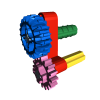
 Watch the Footage The Mecanum wheel is an omnidirectional wheel design for a land-based vehicle to move in any direction. The Mecanum Wheel is based on a tireless wheel, with a series of rubberized external rollers obliquely attached to the whole circumference of its rim. These rollers typically have an axis of rotation at 45° to the wheel plane and 45° to the axle line. When spinning generates a propelling force perpendicular to the roller axle, which can be vectored into: + a longitudinal component + a transverse component Minions use Pulse Width Modulation technology to adjust the speed of their vehicles. Minions change the running direction of each wheel or motor with H-bridge technology and control the movement of their vehicles by combining different wheel directions. Camellia Mini could control all motors synchronously, which keeps 4 Mecanum wheels changing direction or speed simultaneously, thus making the vehicle perform perfect omnidirectional running. www.camellia.xin Copyright © Camellia Café 2016-2021 Camellia Café and its LOGO are registered trademarks.
 -
Hi all, since it's now published on Brick Model Railroader group, I can finally present also here in EuroBricks my second entry, this time in "MOW vehicle" section: You already know it from the WIP thread - it's a small little patchwork of two Fiat 600T/850T vans and a FIAT 500 499,5cc (21HP) motor. Here's the full story! And here's some bonus content!!! Presentation for Octrainber ends here , but there are some other photos: Transmission is on only one axle, as in the prototype, and it's using (again!!! ) the twisted rubber band transmission. The battery is a 200Mah Li-Po, connected to a small circuit in order to charge-discharge and manage the output to the motor. It can be recharged with an USB Adapter (in this case a serial to USB adapted I had at home). And two videos, showing the rubber band transmission and a small track with the 500 in action! https://www.flickr.com/photos/138174786@N04/51670350725/in/album-72157720126403108/ https://www.flickr.com/photos/138174786@N04/51673059120/in/album-72157720126403108/ I hope you like it! Ciao! Davide P.S. for reference! For more information, please refer to this site (it can be translated) https://scalaenne.wordpress.com/2017/07/29/draisina-fiat/ and to this video, showing a restoration of the Fiat 500 Draisina - which inspired the Giovanni and Giorgio story (Italian only, sorry, maybe it can work with subtitles) https://www.youtube.com/watch?v=X7vwRs0Akkk&t=211s
-

Strange Power Functions Issue
jshuiting posted a topic in LEGO Technic, Mindstorms, Model Team and Scale Modeling
I bought a set from bricklink a while ago and tested out the electronics, only to find that they were acting really strange. I'll try to explain it is as clear as possible but i may mess up a bit. So the set came with 4 motors, one of each kind, XL, L, M and Servo, and these all work perfectly fine on my own battery packs and recievers. But now i hook them up to the included recievers, so XL on red, L on blue, but then only the XL motor works. Now i'll switch them arround, but yet again it's only the XL motor that works, but now on the red channel. The L motor does function correctly when hooked up to a different reciever or straight to a battery pack. Further testing shows the XL motor works on all my recievers, both red and blue channels. The L motor works on 2 out of 4 recievers but only on either red or blu side, not both sides on the same reciever The Servo motor worked on none. And the M motor worked on 3 out of 4, also on just one side per reciever, either red or blue. And again all the motors work directly on the battery pack, or when hooked up to known good reciever. So what's going on here? How does one motor work on a reciever, but another does not? Can i throw away the motors or are the recievers at fault here? It's really frustrating because i am in the midst of making a deal with the seller aswell, but i can't without knowing exactly what's broken. It's like the recievers are picky in which motors they want to actuate and which ones not, but how's that even possible? -
You can find a sneak preview od the 3D printed sample on our IG: https://www.instagram.com/p/CLAKIt3B0PG/ Performance is around 10% faster RPM and torque compared to the 5292 motor (cca 20% more power). The polyfuse protection will be increased from 0,9 A to around 1,35 A - still testing the balance between performance and longetivity. Improved attachment possiblities, everything fits as it should in the studless building system The final version color will be between LGB and DBG. It will come with a 30 cm long PF cable plug, so it's compatible with BuWizz 2.0 and PF. Preorder here: https://buwizz.com/shop/buwizz-motor/ More info when it becomes available.
-
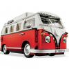
Hi everyone, I know I am asking for a "non existing" part, but I want to create a collective thread for this topic. Maybe someone will find a way.. I am not sure any more because in realitiy this part should not exist, but I can swear that somewhere I saw a german loco (BR 51 or 53) with RED side covers for the 9V motor. Sadly the only thing I found was a "dark red" or "brown" version, what is in fact on a chinese (AUSINI) train. But it depends on the photos. At some pictures it looks like more red then brown: Interesting is the video, where the motor is dyed (not painted), maybe this could be a way to "create" a red train motor. 9V Red Train Motor (dyed) I also thought about to convert a 12V motor into a 9V or PF motor (because of the red cover of the 12V). Did someone tried this out?
-

Best motor for angle measurements
Andman posted a topic in LEGO Technic, Mindstorms, Model Team and Scale Modeling
Hi everyone, I'm searching for the best motor to measure angles. Since I don't have all motors, I'm depended on those, who have them and could a comparison. Requirements: The motor must be compatible with the C+ Technic Hub, used for example in the 42100 The resistance, when turning the motor manually, has to be as low as possible When the motor is turned manually and you stop turning, the motor should not continue to turn with too much swing. 2. has more priority than 3. I have tested the C+ L and XL motor so far. I also have the large angular motor, but it is simply too large. The internal resistance of the C+ L motor was way to high. The C+ XL motor delivered quite ok-ish results. It is just too bulky. Perfect shape and size would be the Medium Angular Motor, which I don't have. Another alternative would be the Boost Medium Linear Motor. I would appreciate, if someone, who has these motors, could do a test for me. A little teaser why I'm looking for this info: I'm building a truck with pneumatic suspension. I using the angles of the suspension arms to detect and control the height. First proof of concept in PoweredUp is already written and working. -
42121 Heavy-Duty Excavator Full RC MOD
Seo-onDaddy posted a topic in LEGO Technic, Mindstorms, Model Team and Scale Modeling
I converted the 42121 Heavy Duty Excavator to a RC version that can be driven and moved. * Instructions are being distributed by Recrickable. https://rebrickable.com/mocs/MOC-69683/Seo-onDaddy/42121-heavy-duty-excavator-full-rc-mod/#details * A 4-port receiver such as 'MOULDKING' receiver or, 'CaDA' receiver or 'Buwizz' is required, and case separation is required.'MOULDKING' receivers do not require any work other than case separation.The 'CaDA' receiver or 'Buwizz' must be removed from the case and the battery must be replaced in a small size.Battery size should be less than 14mm x 25mm x 50mm. * I modified some parts of the exterior because the space was cramped. * fixed the range of operation of the arm operation. -

Odd NXT Servo Behavior
pdmarsh posted a topic in LEGO Technic, Mindstorms, Model Team and Scale Modeling
One of my NXT servos is exhibiting some odd behavior. I had to replace a servo for a different reason and this might be the replacement, but I'm not entirely sure as I didn't mark it as such. In any case, I'm curious if anyone else has seen this and knows the cause. With two servos that act as expected, I can place a single Move block in the program and use any of the duration settings and both servos will run and stop when programmed or run continuously if "Unlimited" is selected. However, when one servo is replaced with the misbehaving one, regardless of the duration setting, the latter servo will run continuously and the good servo will twitch as if it's about to run, but stops immediately. I have to end the program to get the "bad" servo to stop. If I place the Move block inside a Loop set to "Forever," the above behavior will be identical except for one scenario. If I set the Move block duration to "Unlimited," both servos will run and can be controlled by the Loop's "Control" setting, i.e. they will either run continuously or run and stop as set by the loop control setting. Simply using individual "Motor" blocks to control the servos does not solve the problem. There are good and bad programming scenarios with those as well with regard to the bad servo. The best guess I can come up with is that the bad servo is either not sending or not receiving a feedback signal, maybe both. I did wonder, though, if these servos have any firmware in them that might behave differently depending on when they were made. This isn't a fatal flaw as I can use the servo, but I am curious what might be going on. Thanks, Paul -

Lego Pneumatic Engine
LegoEmbodiment posted a topic in LEGO Technic, Mindstorms, Model Team and Scale Modeling
https://youtu.be/UFPNWZeeXQw Lego Pneumatic Engine. What is it? How to make it? The first it needs to finish Lego fake cylinder like in this video https://youtu.be/HcHneyewATE or https://youtu.be/0aZvWva41Ek. The second - to add o-ring to Lego piston like in this video https://youtu.be/wZu-l32Dajw or . -
Hello, I'm a huge train fan and have a section in my city where I have e a narrow gauge. Does anyone have a File or instruction file for a chassis? I really need one as I am very bad with the technic system. also, If you want, just send me a pic of the underside. I will figure it out from there.
-

Fastest Lego RC Ever?
1nxtmonster posted a topic in LEGO Technic, Mindstorms, Model Team and Scale Modeling
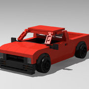
I put together a super-fast mini rc chassis. It has buggy motor geared up 20:16 for drive, and servo for steering. Lipo and v2 receiver provide power. It goes a measured 17.5 KPH (11 mph). So I was wondering if anyone built anything faster. Video:


.thumb.jpeg.bf849dde081326724141a48f3f7b3ad2.jpeg)