Search the Community
Showing results for tags 'offroad'.
Found 88 results
-

4x4 Raid Buggy V2 with 2-speed Gearbox and BuWizz motors
Another Brick in the World posted a topic in LEGO Technic, Mindstorms, Model Team and Scale Modeling
Hello again, Back in March 2023 I started my YouTube channel with my Raid Buggy. Granted, it look somewhat crude and it was quite slow, but it was my first model with BuWizz motors and bricks so it has a special place my heart. Recently it was the 1 year anniversary of it, and I decided to make a remake of it to prove some how much my LEGO building skills have changed and to honor the original model and channel. So enough with the backstory, let's get to the details: Features 4 Wheel drive with a 2-speed gearbox steering with double steering racks Soft double-wishbone suspension Working gear stick Bodywork built to resemble the original model One of the things that I wanted to show with this model was that you don't necessarily need 4+ BuWizz motors in order to make a good fast off-roader. For this, I decided to make use of a 2-speed gearbox, which has a low gear with the same gearing as the Raid Buggy V1 and the high gear which is some 67% faster (6.2 km/h). The gearbox design was heavily based off @Zerobricks's excellent Simple Off Roader but modified to fit my needs. Another benefit of this is that it has a neutral gear, which is very useful for downhills. From then, I finished it off with the axles of my Monstermog and the chassis was done! from there, I had to build the bodywork, the part that I had been dreading the most For me the body was a very important part, as I wanted to make it reminiscent of the original yet it would have a more sporty look and a stronger construction. Just like the first model, it uses many connectors in @Attika's characteristic style. In the end, the bodywork suffered many changes but I consider them for the better, as it now has a more imposing look and a much more sturdy connection so it can be rolled over without having to fear of breaking it. And now a few more images: The model ended-up being a very good off-roader, with a somewhat high speed (6.2 km/h) yet with some torque left for harder off-road. I pretty much had no issues with it, except the front open differential which sometimes got in the way when off-roading in the low gear. It's otherwise a model more focused on high-speed on uneven terrain so I'm happy with it If you would like to build this model, you can download the .io file at rebrickable here. And as always, here's a YouTube video containing some off-road footage, functions showcase, and some nice Punk Rock music Feel free to post a comment about what are your thoughts about it, and see you in the next one! -

WIP On-Road to Off-Road Chassis conversion
CrazyKreations posted a topic in LEGO Technic, Mindstorms, Model Team and Scale Modeling
Hey everyone, I stripped down my Dodge Demon MOC to the chassis and I want to modify it in a way that will make it look more rugged and potentially even have some RC components added! Do you all have any suggestions that you could please give to support the build?????? Here is a before and after of the chassis as of today: The Changes I have made are the following: - Improved central ground clearance - Components of the chassis have been removed to allow the fitment of bigger tyres - Larger Tires - Some reinforcement of the suspension struts and how they connect to the chassis I have a workbench post on rebrickable with a video! https://rebrickable.com/users/CrazyKreations/workbench/6109/ What should I add or change next????? -
Offroad Vehicle Design bible
Zerobricks posted a topic in LEGO Technic, Mindstorms, Model Team and Scale Modeling
I started this project because I wanted to share my experiences building various offroad models over the last decade. This topic is meant to guide the builders with comparisments, suggestion and best building practices, It is however not a place to find already finished and perfected designs - that's up to you. Various aspects of the design of the vehicles will be split into several subgroups and explained in details. 1. Number of wheels First thing we need to know is how many wheels our design will have. Most common setups are as following: 4x4 Setup Advantages: 1. The simplest and most widely setup 2. Having only 4 wheels means lower weight and higher performance 3. Higher manoeuverability 4. Simple suspension and driveline design Disadvantages: 1. With only 4 wheels the suspension has to be designed to be as flexible as possible to get the most out of the wheels 2. In a case of a mechanical failure of a single wheel, the whole model's performance is greatly affected 6x6 Setup with double rear axles Advantages: 1. Two rear axle provide more traction area, especially when going uphill 2. Usually 6x6 vehicles are longer than 4x4 and therefore less likely to tip over 3. Since the front and second axle are usually closer than in 4x4 setup, there is less ground clearance needed between them 4. Greater redundancy in a case of a mechanical failure Disadvantages: 1. Lower manoeuverability due to a longer wheelbase even with rear wheel steering 2. More complex driveline and suspension design is required 8x8 or more wheels setup Advantages: 1. Having 8 or more allows for much greater traction area 2. Ability to drive over ditches 3. Because wheels are usually much closer there is much less chances of getting stuck on top of an obstacle 4. Excellent redundancy in a case of a mechanical failure 5. Better weight distribution 6. Less suspension travel required per each wheel as with 4x4 or 6x6 and hence better stability Disadvantages: 1. Lower manoeuverability even with rear wheel steering 2. Powering 8 or more requires a very complex driveline 3. Depending on a driveline, combined torque required for powering all 8 wheels can destroy gears if a single wheel gets stuck 2. Type of wheels and tyres Now that we decided on how many wheels we want for our offroad beast, we have to look into what type of tyres and wheels we want to use. I will hereby cover only the bigger types of tyres and wheels. 1. 94.8x44R Advantages: 1. Low weight 2. Good thread design 3. Low rolling resistance Disadvantages: 1. Low traction, these tyres are prone to slip on the rim at high loads 2. Due to its rounded shape the tyres tend to slide off obstacles when crawling over them 2. 94.3x38R Advantages: 1. Low weight 2. Medium traction 3. Low rolling resistance 4. Realistic design and proportions Disadvantages: 1. Shallow thread pattern 2. These tyres are very hard and don't adjust to the terrain 3. 107x44R Advantages: 1. Low weight 2. Medium traction 3. Very deep thread 4. Currently largest tyres by diameter Disadvantages: 1. High rolling restistance and vibrations due to the thread pattern 2. These tyres are a bit hard and don't adjust to the terrain 4. Power Puller tyres Advantages: 1. High traction 2. Good thread 3. Largest Lego tyres ever produced 4. Deep wheel offset Disadvantages: 1. High weight 2. Hard to use, they require complex hub assemblies 3. Very rare and expensive 5. Outdoor challenger wheels Advantages: 1. Very high traction 2. Very good thread pattern 3. Deep wheel offset 4. Over 7 studs of space inside the wheel Disadvantages: 1. High weight 2. Hard to attach to the standard axles 3. They require a lot of torque to use them at their full potential. 6. Tumbler wheels Advantages: 1. Low weight 2. High traction 3. Very flexible Disadvantages: 1. Low thread pattern 2. Small size 3. Expensive For the 94.8x44R. 94.3x38R and 107x44R tyres we have a choice of two wheels: 1. Racing wheel large Advantages: 1. Good mounting option with axlehole and pinhole 2. Available in multiple colours 3. Cheap Disadvantages: 1. No inside wheel offset means steering pivot point can't be placed inside the wheel. 1. Futuristic wheel Advantages: 1. Deep wheel offset allows us to place steering pivot point inside or closer to the wheel than racing wheel large 2. Slightly larger wheel size stops the 94.8x44R tyre from slipping on the rim Disadvantages: 1. Limited mounting options, with only one axlehole 2. Hard to find 3. Hubs Now that we have our wheels and tyres we need a way to mount and power them. Here are the most common currently available options: 1. New standard ungeared CV hubs These hubs are usually driven by the CV joint counterpart which pops inside Advantages: 1. Low steering pivot offset - usually at the edge of the tyre: 2. Firm wheel mounting 3. Readily available, easy to use and to build on. Disadvantages: 1. Low operating angle - the CV joint can operate to a maximum of about 30 degrees, which limits steering angle. 2. Very low torque transfer - the CV joints are prone to deforming and popping out even with low torque applies to them 3. Low ground clearance 2. Old ungeared CV hubs Advantages: 1. Low steering pivot offset - usually at the edge of the tyre 2. Firm wheel mounting 3. Better ground clearance than newer hubs Disadvantages: 1. Very low operating angle - the CV joint can operate to a maximum of about 25 degrees, which limits steering angle. 2. Very low torque transfer - the CV joints are prone to deforming and popping out even with low torque applies to them 3. Hard to find and expensive 4. No other mounting points than 4 ball joints 3. Built cardan ungeared hubs Example of a hub using a cardan joint to directly transfer the power to the wheel Advantages: 1. Low steering pivot offset - usually at the edge of the tyre 2. Easy to build 3. Can transfer higher torque than a CV joint 4. Higher steering angle Disadvantages: 1. Mounting relies only on the axle and is not as firm as standard hubs 2. Not capable of transferring high torque to the wheels 3. Low ground clearance 4. Standard portal hubs Advantages: 1. Easy to use and to build on. 2. Can transfer very high torque to the wheels when using 8z and 24Z gear combination 3. High steering angle 4. High ground clearance 5. Firm wheel mounting Disadvantages: 1. Very high steering pivot offset - requires stronger steering mechanisms and more fender space for wheel to swing 5. Built portal hubs Advantages: 1. Easy to build. 2. Can transfer very high torque to the wheels when using 8z and 24Z gear combination 3. High steering angle 4. Higher ground clearance than standard portal hubs 5. Low steering pivot offset when using futuristic wheels Disadvantages: 1. Wheels are mounted and held only by one axle, not as firm as standard hubs 2. Hub relies on friction of the components to keep it together, which can slide apart after prolonged use 6. Built planetary hub Advantages: 1. Highest gear ratio of all other hubs, 1:4 2. Firm wheel mounting when using futuristic of power puller wheels 3. High steering angle 4. Lower steering offset than standard portal hubs Disadvantages: 1. Requires old turntable, futuristic or power puller wheels for best results - all are hard to find 2. High number of moving gears 3. Least efficient due to the high friction caused by the large surface contact area and number of moving gears 4. Suspension Suspension is the mechanism that will keep our model's wheels in contact to the ground and will be supporting most of its weight. Most of the designs cover 4x4's Following factors determine the type of suspension system we will use: 1. Weight of the model - The heavier the model, the stronger the suspension components have to be 2. Speed - Faster models require more responsive suspension systems with low unsprung weight 3. Flexibility - The higher the obstacles you want to climb over the more flex and/or wheel travel suspension has to provide 1. No suspension I have yet to see and offroad vehicle without any type of suspension (except for maybe 42070, 42081 and 42082), but I will list my opinion regardless: Advantages: 1. Simple design - having no suspension simplifies our design...and that's about it Disadvantages: 1. No flex over terrain means, there are only 3 wheels at once touching the ground 2. Low stability 3. Poor weight distribution 4. No shock absorption at high speeds 2. Pendular suspension This is the simplest suspension you can put on your vehicle. It basically means one or more of your axles are free to swing about. When using this suspension I suggest using the small turntable where drive axle enters the axle. This will keep the drive axle from carrying the weight of the model, which causes unnecessary friction. 42030 is a typical example of this suspension system. Advantages: 1. Simple, robust design 2. Using this suspension on both axles can give the model very high flexibility 3. If there are no springs used, the model can have perfect weight distribution on left and right wheel Disadvantages: 1. Large unsprung weight, poor responsivness at high speeds 2. No shock absorption means this suspension is not suitable for high speeds 2. When using on one axle, the stability of the whole model relies on the unsuspended axle. 3. When using pendular suspension on both axles springs or a transfer mechanism are required to keep the model upright 3. Single torque tube suspension This suspension became available with the release of the 8110 Unimog. Best examples of this suspension are 8110, 9398 and 41999. It is the simplest suspension which also allows for vertical suspension movement. Advantages: 1. Simple, robust design 2. Universal joints can be placed inside the ball joint, allowing power to be transferred to the axle 3. Easy to implement Disadvantages: 1. Large unsprung weight, poor responsivness at high speeds 2. Axle requires a some kind of a linkage system to keep it cenetred (panhard or parallel links as seen above). 3. Using this suspension on the front axle usually results in negative caster angle which causes higher rolling resistance 4. When used on rear drive axle, the suspension has the tendency to cause oscillate, especially with soft suspension and high power 4. Hard to connect springs to the chassis 4. Double torque tube suspension This is an evolution of the single torque tube suspension, which uses two ball joints to drive each wheel side respectively. It is my own original idea. Advantages: 1. Simple, robust design 2. Universal joints can be placed inside the ball joint, allowing power to be transferred to the axle 3. Easy to implement 4. Self-cenetring, since axles are connected in the center there is no need for linkages to center it 5. Can carry power to each wheel side independently 6. Drive torque compensation Disadvantages: 1. Large unsprung weight, poor responsivness at high speeds 2. Using this suspension on the front axle usually results in negative caster angle which causes higher rolling resistance 3. When used on rear drive axle, the suspension has the tendency to cause oscillate, especially with soft suspension and high power 4. Hard to connect springs to the chassis 5. Parallel floating axle This suspension uses linkages which keep the axle parallel to the chassis of the model. For best functionality and reliability the lengths of all links and that of the double cardan joint should be equal. Also all the linkages and drive axles should be parallel. Advantages: 1. Keeping the axle parallel to the chassis reduces the oscillations effect 2. Better responsivness compared to the torque tubes 3. Neutral caster angle when used on front axles. 4. Self cenetring when using A arm as upper link or 4 link setup 5. Can be configured to carry power to each wheel side independently 6. If configured to carry power to each wheel side independently the drive torque can be compensated. 7. Easy to connect spring to the chassis Disadvantages: 1. High unsprung weight, less responsive at high speeds 2. Increased mechanical complexity, double cardan joints required to carry the power to the axle 6. Half axle independent suspension This is the simplest independent suspension you can build. Best example of such suspension are Tatra and Pinzgauer trucks. Advantages: 1. Independent suspension with low unspring weight, suitable for high speed 2. Robust design with low number of moving parts 3. Easy to connect spring to the chassis Disadvantages: 1. Changes of the caster angle as the wheels travel up and down 2. Hard to implement a drive system that does not carry the weight of the vehicle 3. Hard to implement steering system 4. Wheels tend to drag sideways on the ground when suspension travels up and down, reducing efficiency 7. Trailing arm parallel independent suspension Personally I have not used this suspension yet, but I did use a normal trailing arm suspension which does not keep the hubs parallel. Normal trailing arm suspension which does not keep the hubs parallel acts similarly to torque tube suspension. For the prallel version of the trailing suspension I imagine the following: Advantages: 1. Independent suspension with low unspring weight, suitable for high speed 2. Robust design with low number of moving parts 3. Long links allow for high suspension travel 4. Very easy to connect spring to the chassis 5. Can be configured to carry power to each wheel side independently Disadvantages: 1. Hard to keep the wheels from sagging under the weight of the model. 2. Difficult to transfer power to the wheels 8. Double wishbone suspension This suspension uses two A-shaped arms to keep the wheel hubs in place. As of late it's my favourite suspension system due to: Advantages: 1. Independent suspension with low unspring weight, suitable for high speed 2. Very customizable design with lots of adjustable characteristics (suspension arm lengths, caster angle, camber angle, steering geometries) 3. When build correctly it is far more robust than live axle suspension 4. Increased ground clearance compared to live axle suspension, especially when used with portal hubs 5. Can be configured to carry power to each wheel side independently 6. Extremely easy mounting of springs 7. Very stable compared to live axles 8. Frame holding the suspension can be part of the chassis, therebye lowering the center of gravity Disadvantages: 1. More moving parts as live axle suspension, increased mechanical complexity 2. Limited wheel travel - Lego wishbones allow a max. of around 25 degrees of suspension angle 9. Multi-link suspension To be updated when I build my first multi-link offroad suspension. I can assume the following characteristics: 1. Independent suspension with low unspuing weight, suitable for high speed 2. Extremely customizable design with lots of adjustable charactersitics (suspension arm lengths, caster angle, camber angle, steering geometries, virtual pivot point) 3. Large steering pivot point compensation 4. Increased ground clearance compared to live axle suspension, especially when used with portal hubs 5. Can be configured to carry power to each wheel side independently 6. Very stable compared to live axles 7. Frame holding the suspension can be part of the chassis, thereby lowering the center of gravity Disadvantages: 1. Very high amount of moving parts, increased mechanical complexity 2. Limited wheel travel - Lego wishbones allow a max. of around 25 degrees of suspension angle 3. Hard to connect springs to the chassis 10. Spring types Listed below are the most common types of springs available: 6.5L Soft shock absorber Advantages: 1. Small, easy to implement Disadvantages: 1. One stud of suspension travel 2. Low spring rate, can't support heavy models 6.5L Hard shock absorber 1. Small, easy to implement 2. High spring rate, can support heavy models Disadvantages: 1. One stud of suspension travel 9L soft shock absorber When using 9L shock absorbers I suggest you do not use the default offset upper attachment point, but use an in-line attachment point instead. This will reduce the friction and allow for better high speed performance Example: Advantages: 1. Two studs of suspension travel 2. More attachment possibilities than 6.5 L shock absorber Disadvantages: 1. Default attachment points create friction 2. Low spring rate, can't support heavy models 9L hard shock absorber Advantages: 1. Two studs of suspension travel 2. More attachment possibilities than 6.5 L shock absorber 3. High spring rate, can support heavy models Disadvantages: 1. Default attachment points create friction 2. Rare and expensive 11. Attaching springs to live axles If we start with basics, the first things we have to check is how position of springs affects suspension of live axles. The closer you place the springs together, the more flex the suspension will have, but it will also be less stable: I suggest you to keep springs at a distance of around 1/2 of the total model width. When placing springs you should keep them in-line with the wheel bearing in order to reduce friction. First example of bad spring placements: And example of good spring placement: When using multiple springs make sure to place them symmetrically centrred to the wheel hub: When attaching springs to torque tube suspension, you have to allow springs to tilt in two planes: You can also attach the springs to the suspension links to increase suspension travel. This technique is especially common on Trophy Trucks: 12. Attaching springs to independent suspension Independent suspension allows for much more flexible spring placement. Generally the closer you attach the spring to the main suspension arm pivot, the higher spring travel you get, but lower suspension force. Examples going from the hardest suspension with low travel to the softest with high travel: You can also attach springs inside the suspension arms: Or horizontally: As with the live axles make sure springs are in the center of the wishbones. Example of good placements: And an example of bad spring placement, which causes excessive friction and suspension binding: 5. Steering Steering is the system which allows our model to change direction. Generally there are two types of steering system used: 1. Skid steering Advantages: 1. Very simple to implement and control with two separate motors for left and right sided wheels. 2. Does not require a dedicated steering motor Disadvantages: 1. Not efficient, since wheels have to skid to steer 2. Power had to be reduced or even reversed in order to steer. 3. Not very accurate 4. Not very effective offroad 2. Classical steering with steerable wheels Advantages: 1. Efficient, with minimum loss of speed 2. Accurate 3. Does not reduce the power of the drive motors 4. Can be used in front, rear or all axles for tight steering radius or crab steering 5. Effective offroad Disadvantages: 1. Requires more complex hub assemblies 2. For best steering accuracy you need a dedicated servo motor. Examples of a simple classical steering system for live axles 1. Parallel steering system for live axles Here both hubs are always parallel. Position of the steering in the front or rear rack has no affect on the steering. Advantages: 1. Very simple and robust 2. Easy to build Disadvantages: 1. No Ackermann steering geometry 2. Steering rack moves inwards as it steers, requiring more space. 2. Ackermann steering system for live axles This system allows the hubs to steer at different rates. The steering arms are offset inside so they form a virtual steering point where at the point where lines meet. Advantages: 1. Better steering performance Disadvantages: 1. More complex assembly 2. Steering rack moves inwards as it steers, requiring more space. 3. Steering system with diagonal linkages This system acts similar as Ackermann steering system by using diagonal steering links. Advantages: 1. Better steering performance 2. Steering rack only has to move in one direction without sideways movements 3. Can be configured to be used in front or the rear of the axle. Disadvantages: 1. More complex assembly 4. Simple steering system for independent suspension 1. Very simple and robust 2. Easy to build 3. Can be even more robust when using double steering racks and links 4. Steering rack only has to move in one direction without sideways movements Disadvantages: 1. No Ackermann steering geometry 5. Ackermann steering system for independent suspension Advantages: 1. Better steering performance 2. Steering rack only has to move in one direction without sideways movements Disadvantages: 1. More complex assembly, less robust. 3. General steering tips 1. When using independent suspension always make sure your links are paralel to the suspension arms, otherwise you may end up with wheels which are not parallel and are causing excessive friction: 2. When using standard portal hubs make sure your steering system is robust enough to deal with the forces generated by wheel driving into obstacles. 3. If possible use servo motors which allow for high steering precision and return to center. They are especially useful at high speed models. 4. Most efficient way to steer the wheels is using the steering racks. 5. Build axles in such way they have positive caster angle, example for direction of travel from right to left. This will self-center your wheels and reduce rolling resistance. 6. Drivelines Drivelines are the responsible for transferring the power from the motors to the wheels. There are various drivelines you can build, here I listed few with their characteristics: Driveline types 1. Permanent 4x4 Advantages: 1. Simple, centralized, low mechanical complexity 2. Wheels are always powered, great offroad performance 3. Light weight Disadvantages: 1. Poor steering radius 2. Tyres have to skid when steering, lowering efficiency of the model 2. 4x4 with open differentials Typical example of this driveline is 42070 Advantages: 1. Differentials allow the wheels to so spin at different rates when steering 2. Very efficient since wheels don't have to skid when steering Disadvantages: 1. If one wheel loses traction, all the power is transfereed to it, poor offroad performance 3. 4x4 with lockable differentials Advantages: 1. Differentials allow the wheels to so spin at different rates when steering 2. Very efficient since wheels don't have to skid when steering 3. All differentials can be locked, so wheels are powered for great offroad performance Disadvantages: 1. Higher mechanical complexity 2. Dedicated motor is required to actuate differential locks, higher weight 4. Axle mounted motors Typical example of this driveline are 9398 and 41999. Advantages: 1. Differentials allow the wheels to so spin at different rates when steering 2. Very efficient since wheels don't have to skid when steering 3. If one wheel gets off the ground the second axle can still pull/push the model. Disadvantages: 1. Higher mechanical complexity 2. Usually the rear axle motor is more loaded than the front, especially when climbing uphill, the motors can't "help" each other. 3. Worse offroad performance than permanent 4x4 5. H drive: This is my favourite driveline due to the following reasons: Advantages: 1. Motors allow the wheels to so spin at different rates when steering 2. Model can skid steer 3. Very efficient since wheels don't have to skid when steering normally 4. Having 2 drivelines allows you to carry more torque to the wheels 5. Redundancy, even if one drive fails the model can still move 6. Wheels are always powered, great offroad performance Disadvantages: 1. Higher mechanical complexity 2. Slightly higher weight 6. Wheel motor drive Each motor powers a wheel independently. Advantages: 1. Motors allow the wheels to so spin at different rates when steering 2. Model can skid steer 3. Very efficient since wheels don't have to skid when steering normally 4. Redundancy, even if one or more motors fails the model can still move 6. Lower mechanical complexity Disadvantages: 1. Motors can't "help" each other 2. Higher weight due to a higher motor count Transferring power axially When transferring power via axles, you can reduce the flex by using connectors instead of simple "bare" axle: Use axles with stops to prevent them from sliding out of gears: Where possible always brace tooth gears from both sides: Transferring power at an angle Where pairs of U joints are used, make sure to align them to eliminate vibrations: Brick built CV joint which can transfer high torque at over 30 degrees angle Brick built cardan joint which can transfer extremely high torque up to 15 degrees angle Brick built flexible drive which can transfer medium high torque, extract and retract, suitable for low angles Transferring power perpendicularly The following perpendicular gearboxes are the best suitable for transferring high torque Avoid knob and worm gears, because they waste energy Gearboxes In my models I generally use the following gearboxes: 1:3 differential gearbox Advantages: 1. Very high gear ratio between low and high gear, 1:3 2. Capable of transferring high torque 3. Very efficient since only 2 gears are used at any time Disadvantages: 1. Takes a lot of space 2. This gearbox requires a good housing to brace the gears properly Compact two speed gearbox Advantages: 1. High gear ratio between low and high gear, 1:2,77 2. Capable of transferring high torque 3. Very efficient since only 2 gears are used at any time 4. Very compact design Disadvantages: 1. Requires two of the rare 20 tooth clutch gears 2. More complex shifter assembly. Diagonal gearbox Advantages: 1. High number of gears 2. High gear ratio possible, over 4:1 2. Capable of transferring high torque 3. Very efficient since only 2 gears are used at any time Disadvantages: 1. Takes a lot of space 2. Input and output axles are not parallel. 3. A complex shifting assembly is required for sequential operation. Driveline effect on suspension Transferring torque on the wheels can affect the suspension, especially when live axles are used. The following photo shows how the torque causes one side of the axle to push down and the other to lift up: In order to minimize this effect I suggest the following: 1. Make sure to have most if not all the downgearing inside the axles, so you do not need high torque going to the axles. 2. Make sure your models have a low center of gravity 3. You can eliminate this effect by using two counte rotating axles which cancel each other's torque, example below: 7. Motors and control Following are the most common types of motors used for Lego models. You can find more info here: http://www.philohome.com/motors/motorcomp.htm My personal favourites are L and RC motors due to the balanced output speed to torque ration and great mounting options. 1. PF-M Advantages: 1. High speed output 2. Smallest available motor 3. Cheap and available Disadvantages: 1. Low torque 2. Poor mounting options 2. PF-L Advantages: 1. High speed output 2. High torque 3. Cheap and available 4. Great mounting options Disadvantages: 1. Odd shape 3. PF-XL Advantages: 1. Very high torque 3. Cheap and available 4. Good mounting options Disadvantages: 1. Slow speed output 2. Large form factor 4. PF-Servo Advantages: 1. Very high torque 2. Very precise output with 15 positions 3. Good mounting options Disadvantages: 1. Slow speed output 2. Output axle can move a max of 180 degrees 3. Large form factor 4. Hard to find 5. 9V-RC motor Advantages: 1. Most oowerful Lego motor 2. Very high speed output 3. Good mounting options 4. Two output axles with different gearing ratios 5. Drive axles can pass through the motor Disadvantages: 1. Low output torque 2. Low efficiency 3. Power hungry 4. Odd form factor 5. Hard to find and expensive Power options 1. PF - AA battery box Advantages: 1. High capacity 2. Good mounting options 3. Works with rechargeable batteries, but with lower performance 4. Cheap and easy to find Disadvantages: 1. 750mA current limit - not enough to fully power RC motor 2. Heavy 3. Has to be removed and opened to replace batteries 4. Wasteful 5. Odd form factor 2. PF - LiPo battery box Advantages: 1. Small form factor 2. Light weight 3. Easy to recharge Disadvantages: 1. 750mA current limit - not enough to fully power RC motor 2. Low capacity 3. Studded design 4. Expensive and hard to find 3. RC control unit Advantages: 1. No current limit - can power 2RC motors at once 2. 3 Power levels 3. Has integrated steering output with 7 positions 4. Good mounting options 5. Easy battery replacement 6. Radio based control Disadvantages: 1. Poor quality, prone to breaking 2. Limited angle (45 degrees) and torque from the steering output 3. Has to be removed and opened to replace batteries 4. Very large form factor 5. Expensive and hard to find 6. Heavy 7. Required dedicated antennas and remote Control options 1. PF receiver and controller Advantages: 1. Receiver is easy to integrate into the model 2. Controllers have physical feedback 3. Cheap and easy to find Disadvantages: 1. IR based, low range, useless outside 2. Lack of PWM motor control, unless using train controller which is awkward to use 3. Odd form factor for use with steering 2. RC control unit See above 3. Third party options such as BuWizz and Sbrick Advantages: 1. Smaller form factors, easy to integrate into model 2. More outputs than PF system 3. Smooth control of motors 4. High range thanks to Bluetooth control 5. Higher power available with BuWizz 6. Customizable profiles Disadvantages: 1. Smart device is required 2. No physical feedback 3. Sbrick is limited by PF battery box 4. Price 8. Chassis Chasis is the backbone of your model which olds everything together. For chassis I suggest you to use the following components in order to make it strong and robust enough to deal with the stresses involved when crawling or driving at high speed: Some flex in the chassis might be a good thing to improve offroad capability, but only if id does not affect the driveline and cause friction on the drive axles. Remeember to use diagonal support, since triangles are the strongest shapes. You can also use panels and motors as structural support. Interlocking your chassis will keep it from slipping apart. For good examples of chassis designs I suggest you check the instructions for 9398 and 42083. -
[MOC] Dune Buggy RC - 8284 Redesigned
cyberdyne systems posted a topic in LEGO Technic, Mindstorms, Model Team and Scale Modeling
Good day/night/whatever everyone! I want to share with you a little experiment of mine that got a bit out of control. I hope, you remember set 8284 and its really unique looking b-model. At least I do. Furthermore, it is one of my favourite b-models and I really wanted to pay tribute to it. Obviuos thought was, of course, to make it RC with the new Control+ elements. After half an hour I got something that could drive and steer. I even tested it in the local park, but... something was off. It just wasn't enough. However good looking this buggy is, its transmission wasn't created with electromotors and speedy driving in mind. Wheels tended to fall off. Gears in diff broke at least once. And offroading capabilities were...em... on the small side of expectations. And I got an idea! I decided not just to motorize this buggy, but completely redesign, reimagine it from technical point of view, keeping exterior close enough to what it was before. You know, like these like-oldtimer-outside-but-modern-inside tribute cars which car companies sometimes make. Also I wanted to make transformation function more interesting and useful. So, I started on the blueprints... And here it is! All modern all new Dune Buggy! With familiar face which got a facelift. Literally. New version of transformation not just shortens the car, but lifts all front section up While cockpit raises up, special levers make sure that headlights between wheels always stay horizontal. And not only that. Another special lever in the rear section locks the differential using new orange shifter. This way buggy becomes most offroad. And now - to the video! (With the new intro btw) -

Lego Technic Tamiya Neo Fighter buggy (but it is 4x4)
Lixander posted a topic in LEGO Technic, Mindstorms, Model Team and Scale Modeling
Among those 3 buggy`s/ truggy`s that I have to test-build them I just managed to add a 4th one. This one is the first 4x4 with 2 motors. As usual, it packs some buggy motors (2 of them, as I said), a servo, removable body (at least semi-detachable), positive caster-angle and full independent suspension. The weight is just under 900g; pretty decent, considering it is 4x4 and that has a pretty big body and some useless pieces to imitate the electric motor of the real RC buggy. Unfortunately, I think that this will only be available with normal RC batteries, because almost no existing hub for Lego is not fitting. -
[MOC] Trial Unimog - Zetros (42129) alternate
gyenesvi posted a topic in LEGO Technic, Mindstorms, Model Team and Scale Modeling
Hi All, Although I have posted a few pictures previously, I wanted to make a proper writeup of my Trial Unimog alternate of the Zetros set (42129), because I think sharing the design process is valuable for people around here. Also, I am going to share my thoughts about the set itself as a parts pack. But for the curious ones, here's an action video of the end result and a short summary of the features: Features: - good actual outdoor performance :) - permanent AWD, no differentials - 2-speed gearbox, faster gearing than Zetros - relatively large increase in ground clearance - 4-link suspension on the back, large articulation, soft suspension - 3-link suspension with Panhard rod on the front, slightly larger and softer articulation than the Zetros - opening (and lockable) doors and trunk bed When building alternate models, I always try to build something different from the A model, both functionally and in its looks. So when considering what to build out of the Zetros, keeping the Mercedes brand but going for a different form factor, my first idea was a G-Wagon - quickly taken by Grohl himself. Then I though, let's fall back to a Jeep - also taken quickly by Tim.. Unimog was on my list of potential alternates, but I wasn't sure about it yet. But one thing was sure: I wanted to improve the actual off-road performance over the Zetros. So putting the form factor aside a bit, I started experimenting with chassis and suspension designs. One option I had in mind was to keep the live axle setup, but improve it to make it actually useful for off-roading: increase suspension travel, ground clearance and responsiveness. Furthermore, I wanted to see how lightweight the axles could be built, because the Zetros's axles are pretty bulky. I was okay with doing away with the diff-lock, since I wanted to use the M motor for a 2-speed gearbox anyway (just like others). During experimentation with axle designs and suspension travel, I have realized that the 3-link live axle setup of the Zetros is not only limited by the springs' short travel, but also by the 3rd link on the top. That link cannot rotate sideways on the chassis side and is mounted very high on the axles, and as the axle tilts, its top can move sideways significantly, and as the link cannot follow it sideways, it limits the axle's tilting movement; hence very limited articulation. The setup only works for a short range of movement as on the Zetros, which is limited anyway by the springs, but cannot work for a setup that aims for more articulation. One way out of this is to allow the 3rd link to rotate and follow the side movement of the tilting axle, but then the axle needs fixing sideways. There are two ways to fix that. Either a 4-link triangulated setup, or a 3-link setup with a Panhard rod. Although the Zetros does use a Panhard rod at the front, it is unrealistically mounted and too short, that would cause kind of bump-'steer' for larger axle articulation (not exactly bump steer, but more like shifting the whole axle sideways). So after taking the limited number of suspension parts into account (only 6 towball sockets left out of 10 since 4 must be used for mounting the front wheel hubs, and only 1 6L link available in the set), I opted for the following design: on the rear axle, I used 4 towball sockets for a 4-link triangulated setup with long links, allowing the upper links to rotate sideways and follow the movement of the axle. The springs are attached to the middle of the lower links. This allows for long upwards movement of the axle at the end of the links, and makes the suspension much softer even with the hard springs. Pretty solid and allows for large articulation, just what I wanted. Furthermore, the axle itself is quite slim and rigid, and has good ground clearance, especially in the middle where it's most needed (as proven by my off-road tests). The front axle was more challenging. First off, increasing the ground clearance is only possible with one trick: the towball socket liftarms must be built at an angle, going upwards in the middle, and that limits possibilities. Second, the steering motor and its mounting takes space on the axle, and is in the way for the suspension mounting points. I have experimented with two other options: steering through a driveshaft coming from the chassis, but the placement of the motor in the chassis was problematic do to space required by all other motors and the battery, along with the largely articulated suspension design; second I tried to put the steering motor above the front axle, actuating steering through a linkage system. Although, this worked quite well mechanically (verified with the Powered Up app), unfortunately, the Control+ app itself killed this direction: the app limits the steering motor angle to about a 25 degrees less than the calibrated range, which is normally 90 degrees or motor rotation, resulting in about 65 degrees in case of the Zetros (that's why it's steering is so bad by the way). Now in my alternative steering design, the max calibrated angle would have been 45 degrees, and the 25 degrees minus by the app resulted in about 20 degrees of movement, resulting in almost no actual steering at the axle. Pretty sad that you can build something mechanically sound and then not able to control it with the app :( So I fell back to mounting the motor on the axle, and used the remaining 2 towball sockets for two lower links, which again, I built longer to allow for a bit more articulation. Luckily, I was able to mount the motor in a way that it allowed to use the single 6L link as the 3rd link, allowing free sideways tilting movement of the axle, as it is attached to a towball pin on the chassis end as well. I also experimented with the spring mounting technique of the rear, but it was weak and wobbly on the front without the 4-link setup, so I went back to mounting the springs on the axle. However, I managed to move the springs closer to the center of the axle, resulting in both slightly larger articulation and softer suspension. Finally, the axle is fixed sideways by a long Panhard rod going from one end of the chassis to the other end of the axle, eliminating bump 'steer' quite well even at larger articulation. As a side note about parts, it would be really nice if the set had another 6L link somewhere, for example as a Panhard rod on the rear axle. It could be used to build another 4-link suspension to the front, and also as a steering link in an independent setup (which is problematic to build for other reasons as well). So after sorting out the two axles and the suspension, I though this could be used in a Unimog chassis. Though not too different in form from the Zetros, but at least it keeps the brand. Furthermore, I decided to make it different in its functions: the first step was focusing on a proper suspension. The second was the drivetrain. And that also caused some difficulties. Unimogs are short. You'd think that's not a big problem at this scale, as many RC Unimogs have been built before, but it is with the latest drivetrain parts. The new CV joint with a sliding axle hole is a whopping 8 studs long!! (Compare that to a 3L U-joint; sure, the CV joint has the axle built in on one side, but this construction limits builds quite a bit. Not sure why the new sliding variant needed to be 2 studs longer, I thought it would be just 1 longer, enough for the sliding, which is typically about half a stud, but 1 stud max). So two of those, plus, two non-sliding ones at 6 studs length, and your driveshaft is already 28 studs long. Add to that the amount of space required by the differentials (2 studs on each end until the axle center), and your axle distance cannot be less than 32 studs. Add one more to get a nice odd length middle section, and we are at 33 studs from axle to axle. It is quite long for a Unimog. (As a side note, I tried to split the driveshaft in two halves, shifted sideways in the opposite direction to let them overlap in length and hence make things shorter, but it did not work out due to the axle length limitation of the CV joint part and also space limitations from the motors). So because of this, and other considerations I decided to do away with the differentials altogether. It saves 2 studs in length. It allows for a slightly faster 12T / 20T gearing; the Zetros is just too slow. Furthermore, it allows for larger ground clearance, as the differential does not stick out from the axle. It even allows for a slimmer axle design, as there is more space in all directions, such as for mounting the steering motor. And last but not least: no differential - no need to lock them :) With unlocked differentials the off-road performance would be bad anyway. Once I settled for the length and the drivetrain, I needed to place the remaining motors and the gearbox. I was able to sandwich the gearbox between the drive motors, and put the gearbox's driveshaft motor on top, the flip-flop beams and the frames proved to be very useful for building a strong but lightweight chassis. The final challenge was the driveshaft from the gearbox motor. I am not sure why TLG used this motor here as it is super cumbersome to work with. It needs substantial down-gearing (and the right amount for your actual application, which is 180 degrees final turn for a gearbox, but 90 degrees for a diff-lock), a clutch mechanism for safety and physical end stops for calibration. These all take up space as they need to be routed somewhere. Things would have been much easier with another L motor.. (Maybe to make the set slightly cheaper? Or TLG is trying to get rid of these motors on stock? They don't seem to fit well into the PU system without positional control.) Anyway, finally the chassis of the Unimog was complete. I used the remaining CV joints to connect the drive to the spinning fan in the front :) The rest was just bodywork and placing that big hub somewhere. I opted for roughly the same position in the cab as the Zetros, but with the cables inside, to allow easy access to the batteries for replacement. For the design and styling, I took some inspiration from online sources like this one because of its color scheme, but I wanted to minimize the cab length as there weren't enough panels for a 4-door version. I built the cab with no opening hood to make it solid :) And also made the doors lockable to avoid them opening automatically when driving around.. Finally, the black panels were just the right size and amount to cleanly finish the bed, both the sides and the floor. The bed floor opens (but lockable) to see the gearbox, and to give room for accessing the batteries. I have also added fenders and the usual decoration like the rollbars, exhaust pipe, mirrors, ladders. Here are some renders of the whole build. As you can see, I did not use any green parts, as they would have only added clutter to the otherwise clean bodywork I think. Some more notes about the parts of the set apart from the ones mentioned above. The set has a good amount of paneling and beams and connectors, although the green parts are a bit less useful since they are limited in number and size. Another shortcoming of the set is the available gears. It has all sizes, but their number is lacking in some cases and hence high gearing ratios are hard to achieve. For example if you try to deviate from the default drivetrain, those gears will be missing for example for a simple down-gearing for the gearbox motor.. More images can be found on Bricksafe. Building instructions are available on Rebrickable. I did not know too much about Unimogs in the beginning, but during the research and designed process I actually came to like Unimogs quite a bit. I like that they are compact but seemingly efficient machines, and the trial versions actually look pretty cool. And I am actually quite happy with the end result. Let me know how you like it and your opinion on the set's parts! Cheers, Viktor -
[MOC] 42099+42110 Defender RC conversion (Control+)
cyberdyne systems posted a topic in LEGO Technic, Mindstorms, Model Team and Scale Modeling
Good day, everyone! This project has started as an idea of creating better a bodywork for 42099, but after some time in development it turned into undependent rc modification of Defender 42110. I took inspiration from Bowler WildCat and Bowler Nemesis which are extreme buggy-like offroaders based on Land Rover cars. So I pondered the question, What if... new Defender would be made into Bowler? In result - original defender has become lower, has got lower roof profile, bigger tires, front and rear pushbars, snorkel pipe, stronger footrests, two sets of additional lights and fog lights, antennas, front and rear mudguards, some chains ('cause chains are cool!). Engine was swapped from 6-inline to V8-supercharged! (After I made this model in spring, LR has announced that they will actually make a V8 Defender. Sadly, not supercharged :) Engine and cooling fan are connected to the front axle via chain links. (Yes, chains ARE cool. I had to buy whole Ducati set for this) And the most important - Control+ components. As this Bow-fender shares control profile with 42099, set of electrics is the same. One XL+ for each axle One L+ for steering SmartHub for SmartThings And then I found out that I am... well... not really good in making offroad chassis. At least it was my first try. So I tuned it as much as possible and made a note for future to learn more about lego offroading. (I think, I'll start with Zetros). Video of how this Bow-fender drives on everything it can is of course here: Watch till the very end! And Thanks for watching. Subscribe. P.S. This cat was walking nearby, while I was making video, so I asked him to participate. So there is A cat in the video now, instead of THE Cat - erpillar :) -
Mercedes Zetros 1833 (42129 MOD)
CrazyKreations posted a topic in LEGO Technic, Mindstorms, Model Team and Scale Modeling
Hey everyone, for a couple of months I've been working on a lego technic camper module that fits on Lego 42129 easily! After a lot of designing, I have come up with a design. I've made a video for all to see and please let me know what you think of this model. This model doesn't affect the Zetros's ability to move in any way (however just to be safe please consider reinforcing the rear axle). It has the following features: Awning Interior with dedicated seating area, bedding and kitchen (kitchen has to be built with bricks haha) rear compartment storage along with a lock Openable windows for ventilation Flexible but sturdy structure for offroading openable door Additional step ladder that can be used to enter the unit Additional storage on the door side of the unit that has a separate compartment to the rear storage space for jerry cans Space for extra wheel -
[MOC] I-Beam Suspension Trophy Truck
paave posted a topic in LEGO Technic, Mindstorms, Model Team and Scale Modeling
Here's my next MOC: I-Beam Suspension Trophy Truck Size: 36L, 16W, 16H, cm Weight: 702g Parts: 843 Features: - Independent front I-Beam suspension - Live axle rear suspension - Opening doors with locks - Opening bonnet with holder - HOG-steering - Fake engine - Modular construction Video: More pictures: Instruction available on Rebrickable: https://rebrickable.com/mocs/MOC-102687/paave/i-beam-suspension-trophy-truck/ -
After my rusty train, I was wondering if I can give the same treatment to a car. I wanted to build a beetle for so long, but I don't wanna copy other's work, and also wanted to make some weird stuff, it's a kinda trademark that I have :P After Several hours of designing, I came out with this Baja Rat Rod based on a Beetle The suspension and steering are fully articulated and posable, but they won't work as real suspension/steering, considered this more like an action figure that you can do some dynamic poses to take some cool photos. Even though most of the car is gone, I tried to keep the recognizable beetle profile.
-

[8081 MOD/MOC] MM //COMMANDO// - Winch is ready!
johnnym posted a topic in LEGO Technic, Mindstorms, Model Team and Scale Modeling
Some might still remember this offroader I started sometime ago in 2019 and showed earlier versions in the 8081 mods thread a while ago. Well, I finally "finished" it now and created digital models for it. I call it the COMMANDO and it is "sold" by MM (Mars Motors). People that follow my Turbo Racers series and my series of 42093 scale cars with swappable engines should already know MM. To show its capabilities I made a trip to a special location and examined what it can do there. Have a look into the video to see what it possible: The configuration in this video has all axles locked and uses the drivetrain variation #2 (see below). The COMMANDO started as the glorious 8081 A model and went through lots of modifications - especially to the front and rear axles and also to the outer hull - on the way to the final result. I created three versions so far: with 1 x PF AA battery box with 2 x PF AAA battery boxes with BuWizz 2.0 ...from which the BuWizz one was used during the video and also most of the time I drove it so far. Here are a few more detailed pictures showing it in that terrain: Here are two pictures showing the chassis construction (click to magnify): ...and here are the three drivetrain variations that can be used (click to magnify) More variations are possible and the gearing can be changed with relative ease, as the motors are not an integral part of the construction: #1 is used for the PF versions and #2 is used for the BuWizz version. #3 can be used to examine the effects of open differentials in offroad situations. The COMMANDO can use various tyres and clearance should be good enough for all of them: 45982 81.6 x 38 R Balloon tyres 18450 81.6 x 44 R (Tumbler) tyres 69912 81 x 35 Tractor (Zetros) tyres I have also already designed a few addons that will be released at a later time - need to create the digital models first - and I have even more ideas for it. So far I have available: front winch rear PTO exploration gear tracks So stay tuned for additions. I hope you like the COMMANDO and I hope it is a worthy successor to the 8081 A model. If you're interested, the - free of charge - digital models (Studio files with detailed steps and submodels) and more pictures are available on Rebrickable: https://rebrickable.com/mocs/MOC-111591/johnnym/mm-commando/ -

[MOC] Lego Jeep Cherokee
filsawgood posted a topic in LEGO Technic, Mindstorms, Model Team and Scale Modeling
Hi all! My new model - is realisation in Lego - off-road custom based on the legendary american SUV - Jeep Cherokee (XJ). Everything according to the canons - axles, a rear differential lock, winch, snorkel, fenders, footrests, thick-walled pipe bumpers, an expeditionary trunk, chandelier and big wheels. -
After 42099 and the whole new PU system, I'm here with a MOC that uses something a bit older - RC system. After all these years it is still the most powerful 100% LEGO solution. Watch it in all its glory: Features: RC drive - 2x RC motor, geared 3:1 (slower output) RC steering Front suspension - double wishbone, soft, long travel, positive caster angle, 7 stud ground clearance Rear suspension - floating axle, soft, long travel, 5.5 stud ground clearance Please watch the video to see this machine in action and for more details. I hope you liked this model.
-

[MOD] 'Rusty Bucket' buggy
SilenWin posted a topic in LEGO Technic, Mindstorms, Model Team and Scale Modeling
Greetings, ladies and gentlemen! I'm glad to introduce you a modification of @Didumos69 Greyhound buggy Yeah, "Mad Max" inspired vehicle again First idea was just "increase durability and add some crawler abilities", but result exceed all my expectations. Adding planetary gear reduction 4:1 to all wheels increase offroad capabilities to sky high (keeping in mind perfectly working suspension of original) And final step - I decide to prepare for summer offroad Lego event in Moscow and for future festival, so I reworked exterior in postapocalyptic style. Other photos Here is LDD model of front hub with planetary gear reduction I used in my modification. Rear hub is done similarly, except for black connectors to suspension arms and without U-joint. Bonus: video from "King of the Hammers" race event in Moscow and photo from "Summer Brick" Lego festival in Taganrog, Russia Thanks to @Didumos69 for his amazing buggy and instructions, and also to @Shurik & @VerSen for cool photos! Hope you like this rusty piece of metal! -

[MOC] Avtoros Shaman 8x8
Madoca 1977 posted a topic in LEGO Technic, Mindstorms, Model Team and Scale Modeling
Hello everyone! Since TLG released 76023, I had been waiting for affordable Technic set which includes so-called Tumbler Tires. So I jumped at 42050 Drag Racer. I also bought some extra tires separately, then revived old project which had failed three years ago. Avtoros Shaman 8x8 Building instructions: Rebrickable Weight: 2550g - 4x L motor for 8 wheel drive - 2x Servo motor for 8 wheel steering - M motor for switching steering mode (AWS and crab) - M motor for winch - 3x LED for front and rear lights - 2x SBrick powered by 2x 8878 rechargeable battery box - Independent suspension for all wheels - Working steering wheel - Openable hood, doors and roof hatch Back in 2013 As you may know, real Shaman is which can go through almost any kind of terrain. It has three steering modes and can scale 45-degree incline. On top of that it is amphibious. Seeing pictures and videos, I instantly fell in love with it.When I started the project, I was too ambitious to realize all features above. Sadly I could not build even steering mechanism while keeping all wheel drive and independent suspension. So I changed the project to building another 8x8 vehicle. It ended up as my Tatra 813 Trial Truck, but that is another story. Focus on characteristic features Two months ago, I suddenly came up with an idea that enables both normal AWS and crab steering. In the case of four-wheeler, you can do it by switching rotation of second Servo motor for rear axle. But in eight-wheeler like Shaman, you should change turning radius of second and third axle. In normal mode, the steering angle of inner two axles is smaller than outer axles. But in crab mode, all axles should be steered at the same angle. This is the basis of steering idea. I used the way of fixing/moving pivot of steering linkage. A: There are two 7L steering racks connected to 7L beams. Front rack is connected in the middle of beam, rear is one stud backwards. Both ends of beams are connected to steering arms of each axle. B: In normal mode, rear rack is fixed by 12T bevel gear. So the fixed pivot of 7L beam is its 5th pin hole. Which makes front end of beam moves twice as rear end does. That means the steering angle of 1st axle is twice as 2nd axle. C: In switching crab mode, 12T bevel gear moves one stud forward and fix front rack. Fixed pivot is 4th pin hole of beam. Which makes both ends of beams move equally. That means the steering angle of 1st axle is the same as 2nd axle. And there is one more twist. D: I put main steering rack (moved by pinion gear) on one stud forward of 7L beam's front-end (which means 9L beam’s front-end). Seeing from the pivot point, this rack is connected to farther than the point of front steering arms connected. So front steering arms always move slightly shorter than main rack does. When Servo fully turns 90 degrees, pinion gear moves the rack in one stud sideways. Steering arms move less than one stud. This was necessary for keeping CV joint (connected to steering hub) rotate smoothly even when fully steered. Challenge and compromise First of all, this MOC is NOT amphibious. It is too heavy to float. And because of driving motors of low position, chassis is not waterproof at all. So it is not recommended driving it through even shallow water pool. My aim was to achieve decent crawling capability. But I had to lower the bar because there was no room left for portal/planetary hub reduction. Without them, heavy load from 81mm tires directly goes to 12T half bevel gears. First attempt was using two XL motors geared 25:9. I put each motor for left/right side of axle. The result was unsatisfied. Even when climbing over small obstacles, bevel gears often slipped and got damaged. So I replaced them with four L motors geared 3:1. Each one drives a pair of half axles. Thanks to their good speed and smaller torque, new drivetrain proved to be more reliable. Although bevel gears were still slipping a bit, I accepted overall performance. The picture above shows two L motors for driving right side of axles. The power functions switch for changing rotation of rear Servo motor is synchronized with moving steering pivot mechanism. In crab mode, rear 4 wheels steer opposite the same direction as front wheels. As always I used few of non-Technic parts. Big roof tile was used for saving weight, curve slope parts were better choice for filling the gap. LBG axles sticking out the roof are visible indicator for steering mode. They are mechanically connected to switching mechanism. In the video you can see how they work. Instructions available at Rebrickable. Building it in red is possible by using red parts instead of white. I hope you will enjoy building! -

[MOC] Lego Technic Chilli Crawler
PunkTacoNYC posted a topic in LEGO Technic, Mindstorms, Model Team and Scale Modeling
I present to you my Lego Technic Chilli Crawler! This is a complete makeover and overall improvement from my previous Carrot Crawler: http://www.eurobrick...howtopic=112037 Yes, I know. This is the second crawler that I named after a vegetable; expect more! Features: - Triangulated 4-link live axle suspension using 4 soft, black shocks. - 4x4 with one PF XL motor mounted parallel* to each of the two axles. A final gear ratio of 1:5.001, yes this may seem slow, but the enormous Super Swamper tires make up for it. - Speaking of that, 4 RC4WD Super Swamper tires. No, they are not Lego, I got them from a nearby hobby shop. - One L-motor for steering in the front axle, geared down via worm gear to 8 tooth gear, then a 12 tooth gear to a 40 tooth gear. The 40 tooth gear drives another 12 tooth gear that moves a 13L gear rack. - Portal hubs for all four wheels. Standard Lego Unimog for the rear axle for rigidity; custom triangular plate portal hubs on front axle for a steering pivot point closer to the center of the tire. - Good articulation, about ~55-60 degrees. - Controlled with an SBrick. - Powered by a Lego rechargeable LiPo battery. - Green Chilli Stem** * The mounting of the drive motors parallel to the axles was a must for this crawler. By doing so, I have not only eliminated gear slippage as there are no perpendicular gears, but there is also a ton more ground clearance in both the front and rear axle. The rear axle especially as the motor is actually on TOP of the axle. Crazy, huh? ** Makes the crawler look so much cooler. Challenges: - As with all 4-link suspension setups, the mounting and placement of both the links and the shock absorbers proved to be a rather annoying, tedious part of the process. I have, however, managed to make a VERY rigid triangulated setup where the shocks are not bent or warped in any way. - The mounting of the two lower links on the front axle was also difficult as there was virtually nowhere I could mount these links onto. I was able to (somehow) securely mount both the lower links and the shocks of the front axle onto 7L and 9L beams on either side of the motor. - Mounting the motors parallel to the axles proved to be hard, but actually somewhat straightforward when it came to the rear axle. I had been so used to having drive axles perpendicular to the axle like on my previous crawler. The mounting of the front drive motor was difficult in the fact that its power is transmitted through various gears and the motor itself is connected to the axle by two plate beams and a pin or two. Although the front drive motor is still not completely rigid, I have had no problems with gear slippage whatsoever in either axle. Some pictures: And finally, here is the youtube video: I welcome any suggestions or comments you may have. I will, however, say in advance that I DO NOT plan on making a body for this crawler as I designed it for performance purposes mostly, a Lego "comp-crawler" as you may call it. Thanks, pt -
Well Guys, i finished my newest MOC,the well known red Pickup from GTA V Character Trevor Phillips.The Canis Bodhi might be one of the most iconic Character Cars from GTA V because it`s a unique Vehicle and it has an interesting little Feature mounted on the Grill. Yes,Trevor had some good Times with Mr. Rasberryjam so the little Bear has to come everywhere. I tried to recreate the Car as good as possible and even added some Gimmicks like a Gun, a Shovel (to dig Holes for Bikers) and an Axe for....well chopping Stuff to Pieces. I also tried some detailing under the Car like the Driveshaft and a Pair of Exhausts. To complete the Pickup,i also tried to make two Minifigs of Trevor himself and Nervous Ron. I hope everyone likes my newest Creation,feel free to Comment and Like. 20161110_154908 by Christian Weber, auf Flickr 20161110_154924 by Christian Weber, auf Flickr 20161110_154931 by Christian Weber, auf Flickr 20161110_154946 by Christian Weber, auf Flickr 20161110_154957 by Christian Weber, auf Flickr 20161110_155029 by Christian Weber, auf Flickr 20161110_155038 by Christian Weber, auf Flickr 20161110_155054 by Christian Weber, auf Flickr 20161110_155119 by Christian Weber, auf Flickr 20161110_155137 by Christian Weber, auf Flickr 20161110_155434 by Christian Weber, auf Flickr 20161110_155442 by Christian Weber, auf Flickr
-
6x6 Truck (Built in 1 DAY)!!!
CrazyKreations posted a topic in LEGO Technic, Mindstorms, Model Team and Scale Modeling
Hello, fellow Eurobrickers! I designed this 6x6 truck today as I challenge and I didn't think much about it but It turned out to be a success (in my eyes). I hope you guys like it. The design was inspired by a mix of old offroad 6x6 military trucks. I say it just needs to do the job and it doesn't need to look pretty while doing it. Here is a list of its features: 6x6 drivetrain springless suspension Modular design Remote control Powered by 2L motors Steering by 1M motor Removable tray (all sides can be dropped. Openable bonnet Openable doors 2 speed gearbox Hi-Low gear For more photos please go to our Bricksafe Page here Please go easy on the look it was built in one day, I would love some feedback. Happy Mocking CrazyKreations -
[MOC] Range Rover Classic
paave posted a topic in LEGO Technic, Mindstorms, Model Team and Scale Modeling
Here's my replication of the classic Range Rover 3 door Info: Scale: 1:13 Size: L35, W15, H16, cm Weight: 1069g Parts: 1085. Video: Features: - 4x4 - Dependent suspension - Panhard rods on both axles - Opening doors, bonnet, tailgate - Adjustable seats - Modular construction - Remote control with PF: 2L, Servo, IR, LiPo. Original truck: Building Instruction can be found on Rebrickable: https://rebrickable.com/mocs/MOC-79523/paave/range-rover-classic/#details -
[42125 Alternate] Dune Buggy
paave posted a topic in LEGO Technic, Mindstorms, Model Team and Scale Modeling
My next alternate model of the 42125 set - Dune Buggy It's a replication of the well-known Meyers Manx dune buggy. Also the BF Injection in the GTA games. Size: L35, W19, H13, cm Parts: 665 Weight: 610g. Features: - Opening bonnet and trunk - Full independent suspension - H4-engine - Working steering wheel. A width is 2 studs shorter, than it's in the original set, so I used the floating differential suspension system. Working well. See the video: Instruction is available on Rebrickable: https://rebrickable.com/mocs/MOC-76011/paave/dune-buggy/ -
[MOC] Lego Technic Cactus Crawler
PunkTacoNYC posted a topic in LEGO Technic, Mindstorms, Model Team and Scale Modeling
Hey Everyone! Here is the successor to my Lego Technic Chili Crawler, the Cactus Crawler It took about half of a year of design and revision to reach its current state, of which I am proud of. THE VIDEO: youtube Features: - 3 L-Motors for drive (two in the rear axle, one in the front) - M-Motor and a small linear actuator for front steering - Rigid, triangulated 4-link suspension for the front axle, with large, soft, black shock absorbers - Extremely rigid 2-link rear suspension with ball-joint pivot point on top of the axle, similar to that found in the RC "Mantis" crawler - 100% Lego-legal custom curved rear links that, with how the main cab is shaped, provide exceptional ground clearance towards the rear of the crawler, allowing it to climb up relatively large vertical structures such as street curbs - Very minimal, light bodywork - BuWizz for extra power and SBrick for a great, custom control scheme Note: By the time I finished designing the cab and it's battery enclosure, BuWuzz had not yet come out with the update for their iOS app that allows a single joystick/slider to control multiple outputs, so I was forced to use an SBrick with the BuWizz, providing the extra power from the BuWizz, but with the ease-of-use and great custom control profiles of the SBrick. When used with the SBrick, the BuWizz does in fact still provide more power than the standard Lego 8878 LiPo battery box. - RC4WD 1.9" Krypton scale tires - Two green pieces so that I can call it the Cactus Crawler ;) LXF hopefully coming soon, the tires can easily be found with a quick google search of their name. YES, I know, there is no body. This is meant for performance, meaning I made the cab as small, light, and rigid as possible. I will be able to reply intermittently throughout the day. I figured I'd put this up now anyway! pt -

[MOC] 6x6 Ural 375D
Sariel posted a topic in LEGO Technic, Mindstorms, Model Team and Scale Modeling
I present a little off-road experiment of mine. It's a large-scale model of the Soviet Ural 375D heavy-duty military truck, a truck I've had the pleasure of driving last year. The model's look is somewhat compromised but it achieved the primary goals, which included stress-testing the planetary wheel hubs, the new differential and my 4-speed remotely-controlled sequential transmission. I'm happy to report that none of these components failed and the truck, which weighs 3.94 kg, is able to drive over a 6 cm tall book or climb inclines slightly above 15°. It's not a perfect model, and it's truly sluggish, but oh well. Functions: remotely controlled drive and steering remotely controlled 4-speed transmission (with the lowest speed disabled so I could use a PF Servo as shifter) remotely controlled pneumatical locking of differentials in all three axles 6x6 drive suspension: live axles #1 and #3, pendular axle #2 (for improved chassis rigidity and to maintain ground clearance) switch-operated rear winch opening hood with a V8 piston engine running at constant speed and opening doors and a tiny detail that I really wanted to get done: a see-through grille -
Eurobricker’s Share your Trailers!!!
CrazyKreations posted a topic in LEGO Technic, Mindstorms, Model Team and Scale Modeling
Hey everyone, you must check out the share your trucks forum for many talented eurobricker’s inspirational truck designs! But this topic is for those who have made their own custom trailers and mods that they are proud of! I will start first Here is my trailer for my custom Semitruck. I am currently designing a nice off-road capable caravan which I hope some of you would like to see, I am almost finished and I will post it here when I am done. -
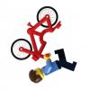
The Crumbling Bridge Last November I built a MOC in which two weird guys lived 30 feet in the air in minimal but cozy stilts. It was called Stilt Houses precisely. In the diorama there was also an off-road vehicle for which I wanted to build a small dedicated setting. Recently I came up with the idea of creating an ironic scene with some building techniques that I had never used, such as the rocks made of many dark bluish gray slopes and inverted slopes. The diorama is quite small but cute, and it manages to get a smile, in this period there is a need… It is mainly composed of three parts: two rocky blocks covered with shrubs and a crumbling bridge that joins them. In the middle the all-terrain vehicle is crossing the bridge escaping from the hungry bear to take shelter on the stilts. Hope you like it! Thanks for stopping by!
-
Hi, I am building next MOC based on model which can be found in the game Snowrunner. I picked KHAN 39 Marshall - it is based on real world vehicle - UAZ 3151. I would like to ask for your advice with one of my biggest problem in mocing - creating a decent looking body. When you see the photos and think "It doesn't look like UAZ..." then YES - you are right and: I wish to focus on body and look (I don't want to discuss functions here, they are there and they are fine). As you can see, the main color is picked (some parts in proper colors are missing, but is not a problem when bricklink is around, the same goes for some missing obvious parts), but any smaller recolors are possible. The biggest problem I have is the front grill. It looks almost ok, but as the grill for Jeep or Land Rover, not the UAZ. I tried to recreate UAZ grill, but I failed miserably. As you can see, there is no much space for it and I am also very pleased with perfect connection of the front and the hood and I definitely will keep that. Important factor is also the fact, that body needs to be as one piece, which can be easily removed, so the body demands some rigidity. Also I plan to add front and rear lights, but at first I need to be sure that the body is right. So, could you help me a little to improve the look so it would be closer to UAZ body look? :)