Search the Community
Showing results for tags 'Rc'.
Found 537 results
-

[MOC] RC Jeep Wrangler - 42129 alternate
gyenesvi posted a topic in LEGO Technic, Mindstorms, Model Team and Scale Modeling
Hey Guys, I'm back with my second alternate model of the Zetros set (42129). As you might remember from the presentation of my Unimog alternate, I was originally entertaining the thought of rebuilding the Zetros into a Jeep, but I passed since Tim has already built one. However, as I kept thinking of how I would do it, it became clear that I had quite different ideas in mind, and it was just too tempting to do it, so I gave it a go. Here I will write down the design process as that seemed to be something interesting for you guys in case of the Unimog as well, and I also prefer such presentations. Features - 3-link floating axle suspension with Panhard rod at the front - simplified rear floating axle suspension with 2 links of limited degrees of freedom and a Panhard rod - 2-speed gearbox with coupled RWD/AWD selector (hi gear is RWD, lo gear is AWD) - smooth and highly colour consistent bodywork - openable doors, bonnet and trunk - detachable hardtop - detailed interior with green accents, built seats - detailed engine, snorkel, minor extras (roof rack, jerry can, fire extinguishers) Here's a real 2-door model in dark grey color which I used as a visual reference: I also used a blue print to roughly set the proportions in a 1:10 scale. Bodywork Interestingly, this model started out from the bodywork, which I don't do often. As a fan of Jeeps, I have long been wondering what the best ways are for replicating its characteristic details, such as the hood and the grill with Lego parts. My Willys Jeep (alternate of the Defender) uses system parts for the (flat) hood and a simple vertical grill, but I wanted to build one with technic panels as well, replicating the slanted surfaces. I have seen two major techniques, one with the long wing-shaped panels (such as the models of @Madoca 1977 and @rm8), and the other with the long curved panel, mainly the classic model of @Sheepo. Since this set has those curved panels in DBG, and the wheels are about the same size as on Sheepo's model, I was wondering if a similar front could be built from the set, especially the angled placement of the curved part, along with the downward slanting of the whole hood, which also needed to be openable. It turned out that with quite a few alterations here and there, the hood could be built, and even better, they could be built using a few large panels only, which makes it look more clean and uniform.. Some arches needed to be redesigned, and the whole became 2 studs narrower, but the proportions worked fine. Then I moved on to the front and the grill, where much more redesign was needed due to different parts available, but after a few iterations with increasing the width and height of the vertical 'bars', I found the one that fit nicely with the smaller lights in the set and the newer curved small panel extenders (and as far as I can tell, newer Jeeps has such bigger grill, so it seemed fine). From there, I moved on to the sides. I knew it was critical to use the BDG panels carefully, because otherwise there would not be enough DBG beams to build the whole body, and I wanted a clean and colour consistent body. I quickly concluded that the doors can easily be built with the large panels, and the windows can also be built with the DBG connectors. The next critical point was to use the thinner long DBG panels in the rear part above the fenders. The difficulty was that they only left one possibility to mount the pieces of the fenders, so I had to use all those black angled beams there, and I had to build the fenders a bit wider so that I can actually connect the two ends to make it a stable piece. Fortunately, the wider fenders also made it possible to build the front ones from black beams at the same angle, even without more available angled beams using triangulation. The last critical piece was to use the small BDG panels in front of the doors, which just fit there tight. If I had to build that section from beams (as I started out), it would have cost too many beams and connecting them to the chassis would have been difficult as well, but the panel solved both problems (unfortunately, it has a drawback as well, which I will cover later). The remaining DBG panels were used in the back, also allowing for an opening trunk. The last tricky part was the rear corners with the lights. I wanted to make them more rounded with the curved panel extenders, but they would have screwed up the proportions, so I just used a slightly curved system brick to give it some curvature. Also I managed to use the black arched beams to replicate the characteristic rear roll bars, and the black tubular parts to build the roll cage, along with the 15L flip-flop beams, which proved to be critical for mounting the roof. The many flat black panels of the set were enough to build the whole roof, along with the side windows in a way that the whole hardtop is detachable from the roll cage as a single piece. Later, when it was more clear what parts remain, I also added the two bumpers, and even a nice snorkel and minimalistic roof racks were doable to give it more interesting details. Gearbox After being satisfied with the rough bodywork, I started designing the functional parts, which I also wanted to put emphasis on, since that's what technic is all about. However, since my Unimog alternate was about the suspension, this time I wanted to focus more on the RC gearbox and build a less articulated suspension which takes less space. I have been tinkering with the idea of a coupled 2-speed gearbox and a central diff-lock for a while (and @Pattspatt also teased me about it), but I never managed to design a compact one, where the drive motors are also placed conveniently. When I looked up a Jeep Wrangler drivetrain, I found this image, which was particularly interesting for me because of the front wheel drive that can be decoupled. Being offset to the side, I thought this could actually be nicely reproduced with lego clutch gears (something similar I already did with my Willys Jeep alternate, not knowing that it's done similarly in real life). After a lot of juggling with the placement of the motors and the gearbox components, I came up with this quite compact drivetrain setup with the gearbox inside the 11x7 frames, which not only includes the drive motors, but the steering motor too (later on that as well). The key ideas regarding the overall chassis structure are the following. First, I use a simplified (limited degrees of freedom) rear suspension, which requires only one CV joint, which makes the rear part of the drivetrain shorter, making more space for the gearbox, which is placed a bit to the back. Second, I placed the motors to the front of the middle section, and use the back of the motors as the mounting point for the front lower suspension links. Thus, the motors play a major structural role in the chassis. Here is the central part: And here is the whole drivetrain without the motors and the frames: As you can see, the rear part is short, and the front is offset to the side, and can just be routed between the drive motors, under the steering motor. Another interesting thing about it, is that it actually has two shafts (yellow axles at the front) coming from the two drive motors (but they are coupled by the red gear in the middle), and one of the shafts powers the 2-speed gearbox, that then goes to the rear axle, and the other shaft powers the the front axle, so the front axle drive does not pass through the gearbox, as it's only active in low gear. The orange selector switches both the gearbox and the RWD/AWD switch at the same time, activating the front of the drive train when low gear is selected. As with my Unimog, the placement of the gearbox motor was again difficult, as a lot of additional elements (end stoppers, clutch gear protection, down-gearing) need to be placed, so the gearbox motor had to be routed out to the trunk. Suspension As I outlined above, the rear suspension is a somewhat simplified live axle. I saw this trick first in @nico71's Ford F150 alternate, but builds of @rm8 use it as well. It is like a ball-joint based suspension, but without the ball-joint as support that prevents the axle from rotating forward/backward. In case of non-motorized models or smaller RC ones with less powerful motors, the joint itself is enough to keep the axle from rotating, but it was not enough in this case (the coupled motors could just rip apart the driveshaft), so I had to fix it explicitly. I opted for a suspension link that does not let the axle rotate forward on the far end, only tilt sideways (not using towball pins, just regular axles). This setup provides strong enough support to prevent the torque from ripping the driveshaft apart. A Panhard rod further stabilizes the axle to prevent sideways movement. Unfortunately, it's still not as solid as a ball-joint would be, and does not relieve all friction from the driveshaft. On the front, I used a similar 3-link suspension as the Unimog, but I had to move the Panhard rod behind the axle as the space was even less in the front, and managed to move the springs further in, giving it a softer and longer travel. It actually came out too articulated and had to be limited, as the wheels hit the fenders. Also, I used a better steering geometry than the Unimog (no anti-Ackermann geometry), and the max steering angle became very good, too good actually, as the wheels hit the bodywork at max angle, and can get stuck in it, so I limited the angle a bit, but is still better than the Zetros (the limiters are just half pins, which can be taken out to get a lot of steering angle, at the cost of risking the front wheel getting stuck in the body at max angle and max articulation, but work pretty good on flat surface). So the suspension is not bad actually, limited a bit by the bodywork, but the model still drives around quite okay on real terrain. Also, I wanted to experiment with a different steering setup, not placing the steering motor onto the axle. As said above, I found it a nice place between the drive motors, and using the CV joints there was just enough space to route it to the axle. It works okay, however, the two joints already introduce some lag in the steering, which is most noticeable when trying to automatically return to center, it does not center totally. But it's still okay and can be controlled with fine adjustments. Interior As the seats in the Zetros set were too small for this scale I needed to build bigger ones. Since I did not want to use the green beams on the outside, I used them as accents on the inside, they were enough to build seats and to be used in the middle console. I entertained the idea of making the steering wheel functional, since the steering motor is not on the axle, but there was not enough space to route it to the steering wheel, and furthermore, the curved panels used as a dashboard just block the way, and otherwise they are important structural elements that hold the front and the sides, so I did not want to alter them. The battery is placed between the B columns, as there was no other convenient place, and there it's easily accessible. The seats can be folded forward, to give room for replacing the batteries. The engine details are just some imaginary ones built from the remaining parts (nothing working). But the snorkel tubing continues on the inside :) Here is the whole chassis with the interior: And here are a few more renders and photos of the complete model, but much more is available on Bricksafe. Building instructions are available on Rebrickable. Let me know how you like it! Cheers, Viktor -
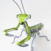
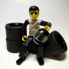
Let´s start with brand new model for the LEGO Technic Challenge. A 29 cm tall figure of American astronaut with moving wrists, elbows and shoulders. The helmet is equipped with two PF lights and both arms are operated by PF M motors. The model is remote controlled and powered by rechargeable LEGO battery.
-
.thumb.png.116032e930e483fb4ebbfdc62183bd34.png)
[WIP] Red Wolf - 4WD RC Buggy /w Buwizz
Didumos69 posted a topic in LEGO Technic, Mindstorms, Model Team and Scale Modeling
Hi, It's been a while, but this winter I got my hands on the Audi RS Q e-tron set with the new wheel hubs for the strong (RC-capable) CV-joints. A year ago I got 2 Buwizz 3 units and a couple of Buwizz motors (their buggy motor remake) and with the hubs and diffs from the Audi I could finally continue a concept that I have working on every now and then over the past few winters. The idea was to create an off-roader with ruggedness and capabilities comparable to my Greyhound 4WD RC Buggy and Make a modular build with an easily removable body, just like with real RC cars Make the Buwizzes easily removable, so you can use them for multiple models Make it easy to reconnect the steering ball joints if impact caused them to detach The wheelbase is 3 studs shorter and the trackwidth 2 studs narrower compared to the Greyhound. The roof top is also 2 studs lower. All in all I strived for a little bit more of a race look. One of the ideas that I started with (about 2 years back), was a setup with 9L steering links that are positioned with a small angle, such that they are actually a little too short (about 0.8%), which gives them a nicely tight fit; when you use them at both the front and rear side of the steering setup that is. With this setup any rotation in one wheel hub translates to immediate rotation of the other wheel hub, without any slack. I also wanted to use 4 Buwizz motors to make the whole thing capable. At a certain stage I had a setup with the old wheel hubs and the new RC-capable CV joints, but I could only make that work for a RWD model, not for 4WD. 4 Buwizz motors on a single axle did not turn out to be a good idea. With melting axles and frames as a result. With the new wheel hubs of the Audi RS Q e-tron I could revert to 4WD and I could finally make the whole thing work. Here's a video of the first successful test-drive with the chassis only. -

RC-Bricks hybrid car
Ryokeen posted a topic in LEGO Technic, Mindstorms, Model Team and Scale Modeling
A bit background about the last few months of tinkering: Some might have seen that a few users, including me, experimented with small non lego/bricks brushless motors and rc parts to build either smaller cars or trophy trucks. I had my own shot on a trophy truck but sadly at that scale some problems couldn't be solved properly. One of those problems was the wheel mounting, i did use hubs with ball bearings from Zenebricks, but with just pins holding them, they would still come of at higher corner speeds. But i didn't want to give up on fusing RC components and bricks, as i love rc cars and i love building stuff. So i thought maybe even with reinforcements a live axle/multilink suspension at RC speeds and offroad just won't work as i want. That's when i thought ok, then maybe some proper on-road or rally car, best with awd or at least 4wd to get more traction and stability. At that point i only had the Zene wheelhubs with bearings and some might have read the conversation about them, they are not suited for a driven and steered axle. I tried to solve that problem but it boiled down to the fact that i needed at least one custom part, either a shortened/custom u-joint or something else. And as i knew that m3 screws fit well into pins i figured that RC parts that are mounted with m3 screws might fit the lego system aswell, so i ordered some cheap tamiya parts as those are widly available and it did fit well. That set the direction for my experiments, fusing RC wheelhups with Lego/Bricks. But wait..they can't connect to Lego axles, so i needed an adapter. I found someone who helped me with a proper cad design and specs, as some of you might have seen in the brushless post, and i ordered some parts. I got them 2 weeks ago and it all worked so well and i build a small prototype. The advantages for me were/are huge, for one, except for the custom parts every other RC part is cheap to replace, all 4 wheelhups cost less than 10€ together. I can replace worn out ballbearings in the hub(and i can clean them) for very little money and there is almost no slack at all in the stearing. Apart from that, by using toe-in/out can be adjusted, left and right wheel steering can be adjusted and the big problem was solved..RC car tires are secured with a proper nut and won't just come of that easy. Fast forward, after all that text, here are some screens: More screens here -> Bricksafe gallery That is my current prototype chassis, currently with on-road touring tires with 82mm diameter. The whole layout is roughtly oriented on most on-road RC cars, except that i choose to center the motor to move it further back and get some weight on the rear axle. Also i choose to not use geekservos even thou it complicated the steering setup but with all that traction i was worried that the geekservo wasn't strong enough. Also i need them for another project, so i put in a cheaper 15kg servo. Features: AWD Adjustable ride height Adjustable steering Adjustable toe-in/out RC shock absorbers Aluminium axles Zene metal differentials Uses common 12mm (1:10 scale) hex mounts for wheels Internal gear ratio is 7.95:1 (spur and diffs) 3250kv brushless motor on 2s (3s possible) 82mm tires And now for the magic custom part: That small part provides the connection between how RC wheels are driven and the lego system and are currently made out of aluminium. It offers a 1 stud long axle part so any axle connector can be attached, be it an common axle connector or a u-joint. The movement range is a bit more than the old lego cv's, i would say about 40 degrees, but that also depends a bit on the RC axle part. A 2mm driveshaft pin needs to be pressed through the hole at the ball end, i designed it that way cause it's easier to manufacture and the pins tend to wear out after some time, so this way i could replace them. There you can see how it's used an the mentioned driveshaft pin that needs to be pressed in. They do need some space to move that's why there is an o ring in the RC axle and a small spring that pushes the driveshaft in a bit. That was only neccessary for the front axle as there is more movement. A first testdrive showed that all the work was worth it. The prototype is fast, stable and fun to drive until a screw(metal 2l pin substitude from a uk shop) got loose cause it was the only screw where i forgot to use locktide :D Next would be more testing and deciding what kind of bodywork i want to do. From the dimensions it's based on a Subaru Impreza WRC but a Skyline should fit aswell. Think it all depends on whether i can find good 80mm rally tires or not. Feel free to ask questions and discuss and thanks for all the fish. -
Fluffy, an oversized proof of concept
Attika posted a topic in LEGO Technic, Mindstorms, Model Team and Scale Modeling
Hello there, it's been a while.... I wasn't entirely inactiv in the last couple of years, but I had a technical difficulty to make videos. Without videos there's no point to post anything, so there it is,a big chunk of can't do attitude... However it has changed. The subject of this topic is on an exhibition now and I was forced to overcome my lazyness and make that camera roll again. To the subject: How did I get this low? I've bought 2 sets of this Audis back in the day as I've found it being a good value for money as a partpack. As a sideproduct I had enough of the curvey panels to get physical on an old idea, the barrel like structure you see on the thumbnail above. Luckily my past granted me an unlimited supply on connectors. As long as it existed only in my head, I was quite sure it is too flimsy and fragile to bare any load, let alone to coop with the centrifugal force that comes with the rolling motion. While rolling around the empty barrel on my desk I figured I could use a somewhat symmetric structure to apply an inward tension on the barrel and that's gonna keep it from falling apart. The fact that the barrel made out of 16 panels made it kinda obvious what symmetry should I use. I put my bet on a 4 spoke solution. The barrel would give a 15.5x15.5 stud square to work with, so I've used a 15x15 structure to reach that inward tension. It is well within the reversible flex of abs, yet enough to keep the circle from pulling apart The next challenge was the attachment of the wheelhub. There is an interlocking frame that holds the sprocket wheel in the center of it.... And so to prove the concept, I had to build a whole chassis around it. For those of you who can benefit from a studio file, here it is: https://drive.google.com/file/d/1uX-avOl3x6DPfGcx_IF1nKzRtAwWqvu6/view?usp=sharing As a sidenote, the io model is a simplified version when it comes to the chaos I've built in the mid section of the frame to avoid the twisting of it. Also I took advantage on the natural flex of the connector body which could not be replicated in the rigid studio enviroment. But I can assure you, no parts were harmed. Some of the data: It is about 70 cm long and 50ish wide, has the ready to run mass of 2.7kg. Uses 4 buwizz motors to drive, a PU L motor to steer and 2 buwizz 3units to get the sparks. Originally I've built it using the slow outputs but on the 2nd testrun I had to try the fast outputs on the motors and it took it like a champ. Although it altered the driveshaft geometry slightly, it had next to no effect on the practical usage. I can't emphasise enough that this car is only a tool to prove the concept of the wheel here. To keep the buwizz units from shuting down, the max output is reduced to 92 percent. This setup gave me fun to play dinamics and a very generous 10 minute + runtime. Way more on both than what I've expected at the begining. The chassis I suppose speeks for itself, nothing out of the ordinary. The lower wishbones have a wider base towards the chassis to deal with the frontal forces. No drivetrain -no loss of efficiency on gears. One thing to mention to fellow builders: I had so much room to work with inside the wheel, when I was building the front suspension, I couldn't stop smiling how effortless to do a "proper job". Meaning caster, camber, and ackermann geometry... Nothing else really comes into my mind, but I'm sitting on this for a half a year now,so I might just be numb about otherwise important details. I'm happy to answer your further questions. Thanks for your attention and feel free to give a honest feedback. My psychiatrist prepared me for situations like this. PS: If you find the panels on the wheels looking suspicious, that's the tape I applied on them to save them from the scratches (as much as possible). -
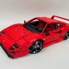
I'd like to present a new MOC of mine - Ferrari F355 Scale: 1:10 Size: 43L, 21W, 13H, cm Weight: 1429g Parts: 1410 Video: Features: - Opening doors, bonnet, trunk - Pop-up headlights - Independent suspension - Remote control with Power Functions - PF: 2L, Servo, IR, LiPo You can find the instruction on Rebrickable page: https://rebrickable.com/mocs/MOC-84040/paave/ferrari-f355/#details
-
Volvo FH and EW 160 Play Set
steph77 posted a topic in LEGO Technic, Mindstorms, Model Team and Scale Modeling
Hi eurobrikers, Here is my current project. A Volvo FH truck destinated to be part of a larger play set using the TLG Volvo EW160. The whole model will have a crane truck full RC, a trailer and the EW160 official lego excavator. As always i build this for my son and so i t needs to be really playable set with lots of function fun to play with. Regarding to this the new Volvo EW160 inspired me. So the concept is to have a fully rc truck with manuals function added to it. The toy will have pneumatics, PFS, RC, manuals functions.... so much for a child to enjoy! My goal with it : Truck : 7 motorised functions + RC PF light = 8 channels on standards Rc official system. Propulsion by L motor Direction by servo on first and second axle with reduction . report to the cab Deploying stabilisator by rotation. Able to set up the stabilisator on 180° : M motor Stabilisator up and down: M motor Crane rotation: M motor First section of the crane arm: M motor Second section of the crane arm: M motor All the these functions are realised and integrated into the framme actually. All working very smothly and with corrects speeds. Time for some pictures of the WIP : I have now to face some difficulties and have to answer some question. What is your opinion guys on these points : 1 Color of the rear crane ? actually thinking for black, to fit with the EW160 design or orange? 2 Position of the two PF receivers, actually in trouble with that, no neat solution 3 tilting bed. The EW 160 is equiped to load a bedactually. Cannot imagine not being able to lift it. The problem is Zero place for an additionnal motor into the frame. Thinking to lift it manualy ? Thanks for your feedback on these points. -

(WIP Thread) Manta's MOCs
Mantarri posted a topic in LEGO Technic, Mindstorms, Model Team and Scale Modeling
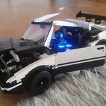
Thought I'd create a thread to just post WIPs of my MOCs, or neat mechanisms. Finished: Generic Muscle Car -
Hello, long time lurker but never contributed anything. I been considering ideas to let my 12v trains also use the 9v/RC tracks and one of the problems was to make the 12v curved rails fit I guess other people have tried this to, but I realize by removing in total 4 stud I would get a snug fit and also a more convenient way to build track layouts. I also modified some straight tracks to be able to connect them with 12v rails switch points etc... I made as short video showing the process using cheap RC tracks and the next step would be using copper tape (and I need a extra set of 9v contact points) for the 9v system, not sure if I want to tape the 12v switch track but I guess I can test it out on a "broken" track. I thought that traction could be a problem but it seems to handle it well (test drive at the end of the video), there is some spinning when starting the train with "high" voltage but at soon as it moves it's coping quite well.
-
Hello Eurobricks community! Let me introduce my latest MOC - Hummer H1 out of Lego pieces. It has approx 3800 parts, incl 7 Motors. Functions are: - Independent suspension of all wheels - 3 RC differentials like in the real model - 8 Cylinder engine - module build - easy removable hood and body. - 4 L motors for drive- Servo for steering- M motor for the winch- L Motor for diffs lock VIDEO: All photos: https://bricksafe.com/pages/Aleh/mercedes_770/hummer_instructions To start this model I was inspired of two things: 1) This video 2) Humvee from CADA Most wanted render: Building instructions are available: https://rebrickable.com/mocs/MOC-174585/OleJka/hummer-h1/#details
-
DMC-12 Back to the Future
Ryokeen posted a topic in LEGO Technic, Mindstorms, Model Team and Scale Modeling
Hello everyone, As i'm kinda done with the exterior, cable management and stuck with the interior progress i'll just show what i got after around 4 months of work. I admit i took some inspiration from a moc on rebrickable from Mr.Platinum. I bought his instructions and asked if i could use some smaller parts like the idea how he did the back light so that's fine. It all started when i was a kid, watching that movie, loving the car and having lego :D and now that i'm older, the parts exists and i have the money i thought, yea let's build a DMC time machine. After gathering reference material and starting on a digital model my goals where set. Make it rc 4 speed gearbox Some light effects realistic interior Gullwing doors Hiding the electronic components Steering wheel should turn Possible leave it without motors as a display model So far i've more or less hit all my goals. Functional satisfied, aesthetically...to many cables. Since i wanted to maybe drive it a bit: Gearbox and lighting is remote controlled Lighting has 4 modes, off, only head/backlights, BTTF lights and both on. Ackermann steering geometry Independent suspension front and read The rc components components are similar to my tropy truck, but here i use a 540 80t brushed motor and 2 geek servos. One for steering, one for the gearbox. Full bircksafe gallery: DMC-12 First i started with building a normal stock DMC-12 so see if everything will fit and to make sure the base body looks good. Also i wasn't sure how to do the planned light effects back then. I tried to somehow mimic the layout of the original car and managed to place the motor above the rear axle. Sadly because gearboxes with lego parts are kinda clumsy i had to place that somewhere else. I thought about a few gearboxes but then just went for a linear layout hidden in the area between the seats. That also gave me space behind the seats to hide the esc, cables and the receiver. Also it served well as a reinforcement for the whole chassis as cars with gullwing doors have a problem to use the roof for stability, at least lego build ones. The real challenge started with the bodywork, especially the hood area, the doors, and the side area around the doors. I first tried to use panels but i didn't like how they were curved and the angles they gave me, also the bigger light blueish grey panels are quite expensive. So i made a rather complex structure to mimic the curvature from top to bottom and the front/back steep angles of the doors. From the shape itself i'm satisfied even though it's not as watertight as some other areas and resulted in quite heavy doors. That's also the reason why they lack a inner covering. But the gullwing doors are stable and with the help of some old lego dampeners(the transparent ones) they stay close and open smooth. The dampeners are placed left and right behind the back wheel arches. Making a time machine out of a Delorean Apart from all the sifi stuff in the back portion of the car a truly important feature, at least for me, was a lit flux capacitor and the blue light around the car during a time jump. The interior is still not fully finished, since i can't decide whether to go more in a modelling direction or just vaguely hint stuff. Flux Capacitor As i could not 3D print anything it was quite a challenge to make one that looks good enough and is actually lit. EL-Wires where one candidate but for that i would have needed a seperate inverter and those are not small nor quiet. So i went for optical fibres, similar to the old lego ones, some drilled holes and some glue. The fibres used are 1.5mm thick. Also i tried to make it like i saw it in the movie, a box with the recognisable Y shape stuff in it, shielded by glass. For the bluer parts of the lighting, when a timetravel happens, i use 3mm thick fibres which again fit nicly through pins so i could secure them well. The good thing for 3rd party parts here is, i could order them in 2m size so i didn't have to use put 2 24l lego fibres end to end and hope the light will transmitt well. 3rd party optical fibres are also way cheaper. I would like to have some cover to simulate the metal nature of those double lines, but no chance except i would 3D print or use modelling plastic sheets. But the cables for the led added to the realistic look as i could mount them where the original car had cables aswell. And of course the needed headlights for some night time driving. Simple 5mm leds fitted into pinholes. So far it was nice to combine all those techs to create something i wanted to build since i was a kid. And even if i need some of the metal parts or the servos and motors, i think i'll just keep it as a display model with lights Feel free to ask questions and have a great day. -
 https://sellfy.com/p/xuuhtq/ https://rebrickable.com/mocs/MOC-30506/Dugald_Lego/lego-technic-koenigsegg-regera-pdf-instructions/#comments https://youtu.be/FcyOmARJhdE Well the teardown of my Koenigsegg Regera is done, instructions are being tested and video is released. Huge thanks to my brother Lachlan Cameron for your amazing teardown photos and killer video edit. Thanks to Justin Wong for being the Guinea pig for the build and your patch notes along the way. Hey all, soo it's been a very long while since I've posted anything. Probably over two years now, however I have been busy in my spare time. For over two years now I've been working on the Koenigsegg Regera. By far my most challenging build to date, especially considering I've been working on Both and HOG and an RC at the same time. The HOG will be Dark Azure/Black centre with White accents and interior. So may I present to you the Regera, it's still a work in progress but everything is pretty well there. It's missing seats, stickers and a few things need adjusting but for the most part it's all there. This car will be on display at the Bricks in the Six Lego convention this weekend so I thought I'd share some early pictures before ones get taken and shared from the show. As always there will be a Video and instructions to follow. But first I need to get the HOG model finished as well. Either way here's some pictures a list of functions. The drivetrain is simple, on the RC it's just drive and steer, no gearbox as the real car is direct drive. 4 L motors for drive and one servo for steering, with a fake V8 in the back, the suspension is where it starts to get interesting, the rear is triplex suspension, unequal length control arms, with integrated sway bar like the real thing, the front is also unequal length suspension, cantalievered with torsion bar and sway bar, the front also raises and lowers a stud and when raising up flaps under the front valance deploy and tuck back up when the car lowers back down. The interior the seats slide and recline, the steering moves up and down in the centre console there's a lever which is a brand new concept which allows you to switch between opening, the left door, the right door, or both doors at the same time. Now when you're opening those doors which are Synchro dihedral the mirrors will fold in as the doors open out and upwards just like the real car. The front and rear clam shells will open as well and there's a lever in the back which will allow you to open the front, the back or both at the same time. On the rear clamshell is the rear wing which is on a cam that raises upward and outward and raises out of the back. The roof is removable like the real car, and can store underneath the front clamshell while still leaving enough room for a tote bag. There's also a manual and an RC model the manual model has two gears the dash the first is to open the doors, and the other to steer. The RC model has drive and steering that's hooked up to the fake V8, the doors and the clam shells are also motorized being able to switch between the front and rear or both at the same time. It also has LED lights front and rear. So overall this is a very in-depth detailed and accurate model in sense of functions.
 -

WIP On-Road to Off-Road Chassis conversion
CrazyKreations posted a topic in LEGO Technic, Mindstorms, Model Team and Scale Modeling
Hey everyone, I stripped down my Dodge Demon MOC to the chassis and I want to modify it in a way that will make it look more rugged and potentially even have some RC components added! Do you all have any suggestions that you could please give to support the build?????? Here is a before and after of the chassis as of today: The Changes I have made are the following: - Improved central ground clearance - Components of the chassis have been removed to allow the fitment of bigger tyres - Larger Tires - Some reinforcement of the suspension struts and how they connect to the chassis I have a workbench post on rebrickable with a video! https://rebrickable.com/users/CrazyKreations/workbench/6109/ What should I add or change next????? -
[MOC] PiPi - small 4WD Drift car
Krxlion posted a topic in LEGO Technic, Mindstorms, Model Team and Scale Modeling
Hi everyone! Not so long ago, I presented a WIP project I was working on, a 2WD Drift car. So the question is, why am I showing you this model. Actually, the best answer would be that I gave up too fast on the previous one and immediately move to the smaller scale. During building this model, I came to the realization that the problem with drifting in the previous car was not with tires (although suited drift wheels are much better), but with the floor I was testing it on. From that moment on, I was testing the model in a different place, where the floor is made out of wooden panels. Features Locked 4WD with different speeds on axles(front 1:1, rear 1:1666) Positive caster angle Working front and rear lights suited for Lego Regular Lego 49.5 mm wheels (15413+56145) Opening trunk Powered by RC setup (with gyro function - helps counter-steer) Design After the first failed attempt to build a drift car fully out of Lego bricks, I still wanted to use rubber tires and achieve my goals. In the time I was starting to build the model, there were at least two similar cars posted, which reminded me about @Anto Hoonicorn MOC. I wanted to preserve his idea of front axle in my MOC and enhance my model by giving its rear axle faster rotation speed, thus making it slip faster. The source of power still remained in A2212 BL motor, in the drivetrain you can see that it was geared down by planetary wheel hub. Model is steered by geek-servo directly connected to the axle, which controls the steering rack. Legend (explanation on stud.io bricks presented in the picture above) 4x yellow stacked 28-tooth gears are in fact a A2212 motor Grey bricks shaped in 5x3x3 are in fact a geek-servo More renders and pictures below Non-Lego parts usage RC setup (DumboRC X6FG, 35 ESC SurpassHobby, SOARIN2 S 1300mAh 7.4V 30C, A2212 1000kv brushless motor, geek-servo, Lucas Oil for lubrication) 1x metal U-joint 4x 1x3 trans-red plates from CADA Finally, I got a short video presenting the model Mass 770g Dimensions 30 x 15.2 x 12.1 cm Scale 1:12.5 GALLERY -
.thumb.png.ac42fe5bf808b68722d021abc3bc5691.png)
[MOC] 1970s rc rally car
Aurorasaurus posted a topic in LEGO Technic, Mindstorms, Model Team and Scale Modeling
Inspired primarily by the Opel Manta 400, I've made my own RWD rally car. It features independent front suspension, and a rear live axle using the big ball joint and a metal U-Joint. Its propelled by 4 buwizz motors and steered by one C+ L motor. Some late WIP photos Earlier WIP photos Problems Because of the narrow wheelbase and relatively high center of mass due to high up buwizz units, the model easily rolls when driving at high speed and cornering. I was lazy with the design of the suspension; the front is too soft and the steering is inaccurate because I am using Instead of the newer parts with longer arms for steering links. This allowed me to fit the wheels inside the body, though. The rear suspension is too hard primarily because I got lazy and wanted it done, after about 8 hours on the model I was getting bored. The bodywork has some parts that could be white if I had the parts in white, but those parts are quite small. If you have any questions, feel free to ask. As of right now I still have the model assembled. Thank you for reading. -
[WIP] 2WD Drift car with pop-up headlights
Krxlion posted a topic in LEGO Technic, Mindstorms, Model Team and Scale Modeling
Hello and welcome in 2024! Today after quite a break (due to moving to a new house) I present you... Well, it does not have a name yet. Although it is kinda based on real car - Ford Probe II (which I own myself). The idea was to create a version of mentioned real car, but with rear wheels drive so it would be able to drift. After some time spent in the building process I convinced myself that I will simply go with the flow regarding body and just slightly base on Ford Probe II. Features Locked 2WD (rear wheels) Double-wishbone suspension Camber (provide less tire contact with the surface and helps drifting) V6 fake engine Regular Lego 56mm wheels (56908+41897) Manual pop-up headlights Powered by RC setup (with gyro function - helps counter-steer) Design The initial idea was to create a car in roughly 1:12 / 1:10 scale that is able to drift with rubber tires. To help achieving this I immediately knew that I need a camber in the car (this section was heavily inspired by plastic gear YT channel). For differential I went with an old 28-tooth one, because this is the only one (I believe) that can be locked. I also wanted to finally have fake V6 engine in my MOC, so by placing another 20-tooth gear in the back of the frame it not only helped transfer rotation to V6 section, but also secured differential, so it cannot skip gears. Source of power comes from A2212 BL motor, it is then transfered to Lego system using slight modification in its shaft (I explained this topic a little bit in one of my previous posts. If you want me to elaborate it deeply, please let me know :). I then gained torque but decreased speed using 46490 wheel hub as transmission. The steering is done by geek-servo, although I have a problem with those, because in fact they are not fully rotating +90/-90 degree, so I needed to put 20-tooth gear first and follow it by 12-tooth so it rotates slightly more than +/- 90 degrees. This solution provides a massive steering angle, which cost me giving up on regular wheel panel arches. So does it drift, that is the question. Answer is yes and no, what I mean by that is that without a body it does have a perfect 50/50 front/rear balance and tuning the gyro helps even further with drifting. I recently started to work on a body and sometimes I do test-drives and I can see heavy impact of that extra bricks. With the body now placed mainly in the front of the car it is a lot harder to handle and it mostly spins like most of lego "drift" cars. We will need to wait for final results after I finish the whole body and tweak everything. The video will be for sure, but not yet (need to learn properly how to drive it and build body ). Time for some renders and pictures Legend (explanation on stud.io bricks presented in the topic) 4x yellow stacked 28-tooth gears are in fact a A2212 motor Red bricks shaped in 5x3x3 are in fact a geek-servo Gloss 11x3 panels with some other bricks that are in two 5x7 technic frames are in fact a battery Front axle close-up Rear axle close-up Built MOC Partly finished body Non-Lego parts usage RC setup (DumboRC X6FG, 35 ESC SurpassHobby, GensAce LiPo 1800mah 11.1V, A2212 1000kv brushless motor, geek-servo, Lucas Oil for lubrication) 2x 3L axle cut to 2,5L (used in driveshaft in each wheel, because of non-standard length) 2x half bush cut in half, so it is 0.25 stud long (used in driveshaft in each wheel, because of non-standard length) 2x metal U-joints Mass (without body) 706g Dimensions (without body) 21.3 x 33.6 x 8.5 cm Scale around 1:11 Gallery -

Flat baja-truck II (or Arctic first-responder)
Lixander posted a topic in LEGO Technic, Mindstorms, Model Team and Scale Modeling
I had an idea of making a small baja-truck for some while and with the Artic vehicle contest it was a perfect match. Here is the concept, made in a Studio file. So, the ”functions” are those of a normal RC car - detachable body, steering and forward/ reverse. For this, the model has 1x servo-motor and 2x buggy motors; with 1x battery hub, it should weight around 800 g or about 28.21 oz. I still didnt found a secure way to attach the battery hubs in the back but I am already thinking of making frames only for BuWizz 2.0 and the MouldKing 4.0 hub, because BuWizz 3.0 has a greater chance of hitting the motors and takes more space too. Also, the suspension travel is pretty big in the front and in the back too, although I have reduced the travel for the front arms because of the over-steer. Here is the almost finished front of the original variant of the model, which had a big over-steer issue. I had to modify the motor frame too. The first 2 images are the concept version and the 3rd image is the last variant, with longer liftarms that allow the suspension to work (you can see the swapped 5L liftarms and the soft springs, which were too soft, obviously). I dont like the current body-work, so the amin thing on the ”to do list” for the Ice baja is to modify the body-work as much as it is possible. Anyway.............in 2 days I kind of managed to finish the chassis. As I only have one buggy motor ”functional” (is partially burned too), I cant test it properly, but I will see what I can do; until then, I am pretty pleased with result of the chassis. More photos will follow with the progress of the new body-work at least, but if I find something to improve on the chassis, then it will be with the chassis too. (The tires in the last 2 photos will be replaced with official Lego ones in the next photos; also, those tires are messy, so sorry for all of that :/ ) -
Another 4WD Drift Chassis Project
FriedlS posted a topic in LEGO Technic, Mindstorms, Model Team and Scale Modeling
Here is my new 4WD Chassis for drifting. At least it is a modification of my previous chassis and it works really good. Propulsion: Monster Motor 1:1 gearing Steering: Servo with positive caster MK Battery Weight: ca. 300g and a short clip of driving: Hope you enjoy it 😊 greetings, Friedl -
Eagle V2 an RC Trophy Truck [MOC]
Daniel-99 posted a topic in LEGO Technic, Mindstorms, Model Team and Scale Modeling
Hello, EuroBrickers! I am pleased to present to you the second version of my RC Lego Trophy Truck EAGLE. To be more specific, this is the third deep modification of the second chassis. Not surprising, as I've been working on this project for over three months now. For a better understanding of this topic it is worth reading about the first version. A better quality photos could be found on my BrickSafe. And a video: First looks: Features Independed suspension at the front with positive caster angle. 4-link solid axle suspension at the rear with anti-roll bar RC shocks (80 mm at the front and 110 mm at the rear) Brushless motor A2212 1200 kv for propulsion, Geek Servo for steering, 1500 mAh 3S Li-Po for power Strong and efficient transmission with metal U-joints and metal bearings. 95 mm RC wheels Light-weight bodywork Main goals "It's never a good idea to stop if you have something to improve." With these thoughts I was preparing a post about my Eagle a month ago. Here's a list of things I wanted to improve: Weight distribution: the heavy electronic components located in the cab loaded the front suspension more than the rear suspension. Rear axle geometry: due to triangulation on the rear axle, the driveshaft and lower suspension arms were located very high off the bottom of the truck, which limited the maximum compression angle of the rear suspension, and the entire chassis was not set to the horizon. Rear suspension setup: a true trophy truck requires a suspension with progressive stiffness. Front axle: steering was very sensitive, rather unusual front triangle shape and tilted lower suspension arms. Overall bulkiness of the chassis. Electronics The Eagle V2 utilizes the same electronic components as the Eagle V1. The story of my choice of such components is given in the post about Eagle V1. Therefore, I will be brief here. Motor: A2212 1200 kv Battery: 3S Li-Po 65C (30C is more than enough) 1500 mAh Controller: 2-3S 35A Transmitter: FlySky FS-GT5 Pros: Brushless motors last longer than brushed motors. High speed and torque in a compact size (about 3 BM in an XL motor) Radio control (best for fast RC cars) Cheap components (compared to Lego electronic components) available at local RC stores. External Li-Po battery allows for different layouts and unlimited power flow. Cons: Requires advanced techniques to build strong transmissions (requires lubrication) Otherwise can easily damage plastic parts. Not an easy decision for purists. Difficult to share instructions with others. Have to take care of tangling wires (same goes for large Lego-is designs). Non-universal solution, suitable mainly for RC Lego machines without a list of additional features. Frame & layout The Eagle V2 has a new "tube frame" (or chassis). This is why I decided not to call it a modification of my Eagle. Let's take a look at it from front to back. All important terms in this section are marked with bold text. In addition, this terms are highlighted on pictures. The front triangle uses the same "almost right" triangle with 14,15 and 6 stud lengths as the Eagle V1. The lower tube of the front triangle is made of two flip-flop beams that have been stacked together. This solution provides a sufficient level of stiffness and resistance to torsion. In addition, I was able to bring the suspension arm mounting points as close to the center as possible. The lower tube of the front triangle is adjacent to the flat bottom made of panels. The upper tubes of the front triangle intersect with the front wall. Further they pass into the side tubes of the cockpit. These tubes are made with flip-flop beams, which allowed me to secure them in place with a 15L front cross-brace (the Eagle V1 cockpit was 2 studs thinner). It's worth noting that the GeekServo motor squeezed perfectly between the lower front triangle tube and the cross-brace of the front wall. Thus, it practically reinforces the front triangle. The cockpit ends at the rear wall, which is reinforced by a rear triangle and structure around the transfer case housing. The side tubes pass into the rear H-tubes (horizontal). At the same time, the rectangular rear triangle is mirrored to form another rectangular triangle at the very back of the truck. The cross-brace on the rear wall is made using L-beams and 3D printed motor housing. Now let me describe the layout of the electronic components. Using a custom transfer case housing, I was able to move the brushless motor out of the cab. It is now located directly behind the rear wall. More importantly, I was able to move the Li-Po battery out of the cab. It is now located above the motor. It is true that this solution increases the center of gravity, but on the other hand it provides excellent weight distribution, which is very important for a trophy truck. The controller is located in the cab next to the driver's seat. Both battery and controller have no pin-holes, but I was able to fix them in place quite greatly. To load the rear axle even further, I added the spare wheel. Bodywork My main goals with bodywork of Eagle V2 were the following: keep it light keep the original shapes of Eagle V1 improve the proportions As a result I made the whole truck one stud longer and two studs wider than the first version. Now cockpit is wide enough to fit the driver`s seat. Also I changed the bonnet and the front grill. Finally I changed the very back of the truck to make it closer to real prototypes. I have to add, that not only the bodywork make the car look good. More importantly to keep the proportions in the chassis. The authentic look of the Eagle V2 is achieved with the proper settings of the suspension. Transmission I'd like to make a 3D model of my truck and show you a nice rendering of the drivetrain, like some great technical builders do. However, the Eagle V2 has a lot of custom parts and a bunch of "illegal" techniques like "almost rectangular" triangles. So I will just mark out the transmission components: Brushless motor with custom housing with planetary gear inside (1:4 gear ratio) Central transfer case with 28:20 gear ratio Rear differential with 12:28 gear ratio The transmission is built on carbon fiber axles and metal U-joints. It is separated from the frame by metal bearings. Metal bearings are used in the center transfer case, in the 5x7 frame that holds the differential, and in all the wheel hubs. I also lubed the planetary gear inside the engine case. Suspension geometry As I've said before, trophy trucks are all about suspension. So the main reason I did a V2 of my Eagle is to try and improve the suspension (both front and rear). Front suspension: Truth be told, not all custom parts turn out to be universal. On the contrary, the idea of efficiency in certain places and the idea of universality are not compatible at all. The Eagle V1 front wheel hubs are a prime example of this principle. They were originally designed for IFS street cars with smaller wheels. Therefore the basic ideas are present in their geometry: An inverted ball joint for the lower suspension arm (which is great in general). Combined with the tilted front suspension, they looked nothing like real trucks. The steering arms were 0.5 studs long, which resulted in very sensitive steering. I also didn't really like the 8 stud length suspension arms, which required custom of steering links to work properly. So I designed a new front suspension system that includes: 9 stud length suspension arms. New hubs (originally designed for live-axles) with 1 stud length steering arms. Thus hub does not use the ball joints! The new design is a deep modification of the Falcon trophy truck front suspension, which has proven to be reliable. In the V1, I used 8-studs suspension arms to fit within a certain chassis width and maintain a strong lower tube of the front triangle. However, by using stacked flip-flop beams, I was able to keep it 1 stud wide without losing stiffness. Rear suspension: It won't surprise you that the Eagle V2 has a new rear suspension. Here's a list of the changes: A new rear axle has been designed (again with a different set of custom hubs). It's more compact than the one the V1 had. The upper triangle of the suspension arms has been inverted (to match the real-world examples). New lower arms have been build. Now the live-axle was given the necessary degree of freedom. The attachment points for the suspension arms were lowered by two studs. This modification was possible due to the changes in the drivetrain described above. The anti-roll bar has been redesigned to match real prototypes. It resists to the twisting effect of the rear axle that appear in the acceleration. Shocks "Once a perfect suspension geometry is achieved, one may look for a proper set of shocks springs" The best springs Lego ever made are the hard 9.5 L springs, because they have a good amount of travel and responsiveness. For example, the 9.5 L soft shocks are not as good because the spring force has a hard time overcoming internal friction. On contrary, the 7L hard shocks have little travel and not enough stiffness to work properly with the hard springs. So I used 9.5L hard springs in the Eagle V1 and early versions of the second chassis. I tried to build a progressive rear suspension using Lego springs, but was not successful. The resulting design was either too unreliable or too bulky. I guess I lacked luck and skill, but I couldn't build a suspension that was both soft and shock resistant. It was either too stiff to absorb big bumps or too soft. So I decided to use RC shock absorbers to properly address this issue. RC shock absorbers have different springs that allow you to adjust SAG and progression without having to move the shock absorber mounting point along the suspension arm. I once tried to adapt RC shock absorbers to Lego, but couldn't find a suitable way to attach them to the Lego pins. Fortunately, a working solution was offered by Ryokeen in his Generic Brushless Trophy Truck. I again had to modify the chassis to fit 1:10 scale RC shock absorbers. Front suspension has 80 mm shocks with 2.5 studs travel. I mounted it behind the suspension arms as it is done it real Trophy Trucks and many RC scale models. There was a way to place it through the upper A-arm, but such solution required 4L liftarms. In addition it had not freedom in the choice of mounting points. Rear suspension uses 110 mm shocks with approximately 3 studs of travel. Additionally they have a dual spring setup, which give the desirable progressive hardness to the rear suspension. Again, I tried to mount rear shocks in the same way it is done in real Trophy Trucks. Developers diary. 3-7 Sep An Eagle V1 was finished. The driving tests started. Front wheel hubs are the same as in Hornet 4x4 Buggy. 11-15 Sep The new front triangle has been built. Now truck has a tilted lower tube and positive caster. The differential has been changed from yellow to red one. 17 Oct I stated developing a new chassis with a different set of ideas behind. (mostly with the triangulation in the rear axle removed and central transfer case added). 24 Oct First prototype of the new chassis has been built. In addition to the redesigned rear axle, I made a new front axle with a shock coming through the upper A-pillar. 27 Oct I started building a bodywork for a new chassis. 1 Nov The first modification of the second version of Eagle has been finished. I started the driving tests. The rear suspension has a new idea if mixing anti-roll bar with additional shocks to achieve progressive suspension hardness.... that was a total madness... 8 Nov The whole chassis has been widened by 2 studs for better proportions. 14 Nov A new rear suspension ideas has been applied. The back of the Truck has been changed. Now the rear suspension has two sets of hard 9.5L springs on each side. Progressive stiffness... Bulky realisation. 25-28 Nov RC shocks has been added. For that reason both front and triangles has been redesigned. -
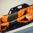
Hello All!! I'm very happy to share my latest Technic supercar design, the BMW M4 GT3! I spent the entire summer working on the chassis, trying to make use of the new Ferrari Daytona parts (rims, differential, panels) to create a fast RC design with full turning capability and full speed. My latest design, the 1:7.5 BMW M4 GT3! by lachlan cameron, on Flickr This build features 5 different suspension ride heights, 3 of which have torsion bar suspension, full RC drive and steering with working steering wheel and lights, manual option with HOG, door locks, opening hood truck and doors, inline 6 engine. BMW M4 GT3 by lachlan cameron, on Flickr I wanted the suspension to have an easily adjusted height, something that can be switched on the fly, and to be able to create a racecar stance, lower at the front and taller at the rear, all while being fully functional in RC mode for each height. My latest design, the 1:7.5 BMW M4 GT3! by lachlan cameron, on Flickr The new differential allows minimal friction, allowing this car to hit a very comfortable speed with 1 buwizz and 2 buggy motors. The steering is very nimble with full turn capability, and even more so with Andrea's brand new design - custom create rims that actually remove the brake disk from Lego and use his own designed hubs to sink the deep disk rim inward, while still providing functionality to the RC drivability thru the u-joints. My latest design, the 1:7.5 BMW M4 GT3! by lachlan cameron, on Flickr @snakeeyes_friex designed the livery, this man can design without boundaries. Honored he could help with this model and all the hard work. Thats all for now... more photos to come! Enjoy! My latest design, the 1:7.5 BMW M4 GT3! by lachlan cameron, on Flickr My latest design, the 1:7.5 BMW M4 GT3! by lachlan cameron, on Flickr Motor options - Buwizz 2.0 or 3.0, old motors / new motors by lachlan cameron, on Flickr My latest design, the 1:7.5 BMW M4 GT3! by lachlan cameron, on Flickr My latest design, the 1:7.5 BMW M4 GT3! by lachlan cameron, on Flickr My latest design, the 1:7.5 BMW M4 GT3! by lachlan cameron, on Flickr
-
Finally, the 2022 LEGO 10300 Back to the Future Time Machine the DeLorean - motorized with powered up ★ Building Instructions on Rebrickable (klick) ★ Features remote controlled motorization - fast driving, 40° steering angle - No scratching gears or rubbing tires Cockpit untouched not flying, but you can still modify it for Back to the future I, II and III version easy to reach Battery box for charging and switching on Off Battery box, Motors and Cable well hidden to not change the looks LED light kit fits in (discount code included) will add Instructions to make your own adapter to power the light kit from the buwizz instead of a seperate battery polygons very close to the movie (not flat as LEGO did it) Multi language instructions: ►english ►deutsch ►italiano ►française ►español ►čeština ►русский The Partfinder: An Inventory of left over parts in all bags to find the without scrubbing through all bags while buildingfor building from scratch Buwizz Profile - my programming for the buwizz included. ★ Details 40° of steering angle with virtual pivot point to not rub against that narrow frame Driven by upgeared large motor No Batteries in the interior, it is still there. Hood is still opening. switch the car on and off and charge from below I added a fix for the gull wing doors to stay up. Also I took the liberty to change the colors of some red/orange/tan bricks that you could see when opening the doors. I will put the bricks needed into the spare parts of the inventory. No instructions for the lights included, but they come with the Light kit. AND: I bought all my light set from Game of Bricks. And (after talking to them) I can give you a discount for a light kit for any of my motorizations. The code is included in the downloads.
-
[MOC] RC Telehandler
legomarat posted a topic in LEGO Technic, Mindstorms, Model Team and Scale Modeling
After several years I am back! My latest MOC is Lego telehandler based on CAT TL642. Since it is not an exact reproduction I decided to change name and logos. Buwizz and iPad are used to control it remotely. There are four motorized functions: drive with PF L motor, boom elevation with PF L motor, fork tilt with M motor, and steering with PF servo. Front wheels are driven through a differential, and the rear axle has a simple suspension. Overall, it is maneuverable, easy to operate thanks to the proportional control of Buwizz, and very fun to play with. Please check out my flickr and https://www.flickr.com/photos/marat_andreev/ my instagram www.instagram.com/legomarat/ Interior controls are made with stickers Also I found a nice reflective sticky paper to make mirrors -

[MOC] - RC 3 Speed Transmission for Land Rover Defender using Powered-Up app.
NikosSprocket posted a topic in LEGO Technic, Mindstorms, Model Team and Scale Modeling
I am building a RC version of the Lego Land Rover Defender (42119) and it will include a 3 speed sequential Transmission. It will be operated from the Powered-Up Lego app. using 3 buttons and it includes a dial that shows the selected gear. I am using a Technic Hub (88012) and a Technic Medium Angular Motor (45603). The Remote Control has 3 buttons; up-shift, down-shift and neutral. When the application is started it calibrates the shifting axle to be at the "neutral" gear and sets the angle to 0. Pressing the up-shift button will engage the 1st gear, then if pressed again the 2nd until it reaches the 3rd gear. If you press the up-shift button more times it will not move the shifting mechanism but will make a "clanking" noise. Pressing the down-shift button will sequentially shift to the next lower gear until it gets to neutral where again will make a "clanking" noise trying to go lower. To the right of the 3 buttons there is a dial that indicates the gear is selected. [Media] -
[MOC] EAGLE an RC Trophy Truck
Daniel-99 posted a topic in LEGO Technic, Mindstorms, Model Team and Scale Modeling
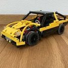
Hey, guys! After a 3-month brake from Lego, I am glad to show you my new RC trophy truck, called Eagle. I apologise for the quality of photos and I will try to improve them later after I will get myself a studio light. I will also make a proper introductory video when I will get enough outdoor footage. Features Responsive long-travel suspension with 4-link live-axle at the rear and double wishbone at the front Brushless motor A2212 1200 kv for propulsion, Geek Servo for steering, 1500 mAh 3S Li-Po for power Strong and efficient transmission with metal U-joints and metal bearings. Great ground clearance for outdoor use, 95 mm RC wheels Light-weight bodywork Experience and Inspiration I guess that nobody will be surprised If I would make a confession that I have a deep passion for Trophy trucks. This type of vehicle suits the best for the role of a fast RC Lego cars which are build for outdoors. Indeed, outdoor environment is always rough and "bumpy" for Lego cars. I took my inspiration and first experience form several well-known Lego builders, such as: Sariel RM8 ZeroBricks GooberReboot Through the last 3 years of intensive engineering I made a few attempts in building myself a "proper" trophy truck. Each of them had it`s own features and technical problems: Heavy-duty Trophy Truck: RWD, 2x BM, 2x Buwizz 3.0 units, 95mm wheels. Problems: "big scale" which caused a serious load for motors, over-tilted front caster. Phantom: RWD, 2x BM, Leshy control unit, 85mm wheels, mid scale. Problems: lack of power from Leshy unit, lack of articulation at the rear, plastic wearing in the wheel hubs. Wilde Beast: 4WD, 4x BM, Wixy RC control + 3S Lipo, 95mm wheels. Problems: "big scale" which caused a serious load for motors, indep. susp. with a questionable geometry. Falcon: 4WD, 4x BM, Wixy RC control + 3S Lipo, 75mm wheels. Problems: indep. susp. with a questionable geometry, overheating of motors at the maximal RPM. About a year ago I switched from Lego Buggy motors to a Brushless motor (for the reasons which will be covered later). This was not an easy switch for me and I had to learn some RC electronics theory and find the proper ways of using brushless motors with Lego. My latest RC cars with Brushless motors was: Unimog trial truck Pathfinder SUV Hornet 4x4 buggy With pathfinder and Unimog projects I studied the 4-link live-axle suspension geometry, while with Hornet project I found the way to achieve a proper suspension and steering geometry with my custom wheel hubs. With this projects completed I get myself all cars I need. - What should I build next? With such question in mind, I faced a deep burnout from Lego, so I decided to take a summer brake. Hot summer days returned me my passion for Lego, and I had a plenty of time to plan a new project. I felt myself ready to make another attempt in building myself a "proper" trophy truck. That is how the story begins. Electronics With my latest truck Falcon I reached the limit of what Buwizz motors could handle. Some time ago there was a discussion about efficiency and power-to-weight ratio. I would not resist that with the growing number of motors and Buwizz units, one could get a better power-to-weight ratio, though such a way faces the problem of plastic-weariness quite soon. With the growth of the number of motors, also grows the size of the car and it`s total weight, which get distributed to the four Lego plastic wheel hubs! I faced the plastic-weariness problem of Lego hubs with my Phantom truck, and solved it by purchasing custom wheel hubs with metal bearings, which I were used in the Falcon truck. Moreover, there was no gearing in the transmission of the Falcon truck: each wheel was connected to it`s own motor via driveshaft with metal bearings. With 4x Buwizz motors on board, powered by strong 3S Li-Po battery, Falcon had a great power-to-weight ratio. Through multiple tests I found that It can not handle full throttle for more than 45 seconds due to the rear motor overheating. It was pretty clear to me that RC Li-Po could easily overfeed 8 or even 12 motors with power, so there was no sense in adding more BM motors. Likely to me, one Russian AFOL developed a 3D-printed housing for Brushless A2212 motor which allowed to use it with Lego. I purchased two sets from him, and mot I have 100% RC setup. There was no problem with the lack of power or motor overheating anymore, but it was a real challenge for me to overcome this energy! Transmission With BM motors it is very natural to distribute the torque among axles \ wheels, by having separate transmissions to each axle \ wheel. But with Brushless motor I had to use "realistic" transmission, since there is only one output with a plenty of speed and torque. Despite the fact this motor is a baby-motor in the world of RC cars, It has enough power to twist Lego axles with instant reaction to the throttle. Custom 3D-printed housing has a 4:1 planetary reduction, but the speed of the output is enough to cause gear-melting. That is why the following decisions were made: use metal U-joints all around, most of them have a 3L lego axle glued from one side to prevent them from falling off. use silicone grease to lubricate the planetary gear in the motor housing and some external gearings. use custom parts with metal bearings to separate the transmission from the car frame. use carbon-fiber axles in the central driveshafts. The new Eagle truck has a very simple RWD transmission with a single "external" 14:23 gearing in the differential. Recall, that the 3D-printed motor housing has a 4:1 gear reduction. So the motor is connected to the differential via carbon-fiber driveshaft. From the differential power translates to the 95 mm RC wheels via half-axles with metal U-joints. The whole transmission sit on the metal bearings (custom wheel hubs with metal bearings, custom 5x7 frame with metal bearings for differential housing, motor output passes through the connector with the metal bearing). Surely you have noticed that I lifted the central differential by one stud over the wheel axle in order to achieve a higher ground clearance! Which differential to use RED or YELLOW? RED differential has a 28:12 reduction which reduces the load from the driveshaft and the motor. Moreover, such gear ratio is more realistic. On the other hand, YELLOW differential has bigger teeth so it is stronger. But more importantly, is that YELLOW differential is 125% more efficient than the RED one, since it has bigger gears and does not scratch the 5x7 frame under the load. In fact, I am using a custom torsen differential with 23-tooth gear. It also does not scratch the 5x7 frame and hold half-axles much stronger than the original YELLOW diff. Suspension Trophy truck is all about suspension, and it was the most challenging part for me! Non of my previous trophy trucks has a proper suspension: it was either rear live-axle without articulation (Phantom, heavy-duty trophy truck) or independed rear suspension (Wilde Beast, Falcon). As I found from multiple driving tests of Phantom, rear axle need an articulation, cause otherwise RWD car loose the speed on bumps. IRS give the desired articulation and stability, moreover it is very simple to build and it has a low unsprung mass. Despite that IRS has a limited articulation and it is not presented in real Trophy Trucks either! Lego engineers designed a ball-joint connection, which is used in many Trophy trucks. It gives a single-lever suspension (with it`s simplicity and stiffness) and desirable articulation. Well, I did not use it, since it has no metal bearings for the U-joint inside the ball. So I had to replicate the 4-link live axle. 12-long reinforced suspension arms, invested upper triangle, 9.5 L springs, attached to the mid of lower suspension arms, Anti row-bar with a carbon-fiber axle, Now let`s move the the front suspension. Surely, real Trophy Truck has a complex front suspension, which is impossible to replicate with lego bricks. Though lego-ish version share important principles with real prototypes: double wishbone with 8L suspension arms (9L was too wide here) Positive caster angle Reinforced lower arms Shock is attached to the lower arm closer to the center of the car Steering rack is located in the front of the car Again I use custom wheel hubs with metal bearings. They have an inverted lower arm mounting point, though it is possible to use Lego hubs instead. With hart 9.5 L springs the front suspension has a long travel, moreover it has a great balance btw softness and responsiveness + side-way support. Bodywork & Frame In order to achieve a positive caster angle I tilted the lower part of the frame. At the same time, the upper part of the frame. At the very front of the car upper and lower parts of the frame meets together which form the "almost right-angle" triangle with lengths: 13+1, 14+1 and 5+1. (right-angle triangle has the following lengths: 12+1, 13+1 and 5+1). Second time I use the Pythagoras theorem to make a force triangle for the rear springs attachment points. I tried to keep the frame of the truck in 13-15 studs wide, to use 15L liftarms for cross braces. I was Luckily to me I was able to squeeze all electronics into cockpit. This give the model 50:50 weight distribution and a "low" (for such high car) gravity center. Well, one would prefer to obtain 35:65 weight distribution for the RWD truck, but It would raise the gravity center and would require extra structure over the rear axle. The whole bodywork consist of 24 panels and a few bricks, so it does not cause much weight to the truck. -

[MOC] Dune Buggy RC - 8284 Redesigned
cyberdyne systems posted a topic in LEGO Technic, Mindstorms, Model Team and Scale Modeling
Good day/night/whatever everyone! I want to share with you a little experiment of mine that got a bit out of control. I hope, you remember set 8284 and its really unique looking b-model. At least I do. Furthermore, it is one of my favourite b-models and I really wanted to pay tribute to it. Obviuos thought was, of course, to make it RC with the new Control+ elements. After half an hour I got something that could drive and steer. I even tested it in the local park, but... something was off. It just wasn't enough. However good looking this buggy is, its transmission wasn't created with electromotors and speedy driving in mind. Wheels tended to fall off. Gears in diff broke at least once. And offroading capabilities were...em... on the small side of expectations. And I got an idea! I decided not just to motorize this buggy, but completely redesign, reimagine it from technical point of view, keeping exterior close enough to what it was before. You know, like these like-oldtimer-outside-but-modern-inside tribute cars which car companies sometimes make. Also I wanted to make transformation function more interesting and useful. So, I started on the blueprints... And here it is! All modern all new Dune Buggy! With familiar face which got a facelift. Literally. New version of transformation not just shortens the car, but lifts all front section up While cockpit raises up, special levers make sure that headlights between wheels always stay horizontal. And not only that. Another special lever in the rear section locks the differential using new orange shifter. This way buggy becomes most offroad. And now - to the video! (With the new intro btw)