

Daniel-99
-
Content Count
211 -
Joined
-
Last visited


-
FALCON RC Trophy Truck [MOC]
Daniel-99 replied to Daniel-99's topic in LEGO Technic, Mindstorms, Model Team and Scale Modeling
Hey! Thanks for your questions! Yes, it uses the slow output, because of the front suspension structure, also I wanted to save motors from extremal loads. I guess, you can use some ideas to build a similar front suspension with Aude hubs, but it will require a list of changes (mostly because the wheel hubs I use have inverted lower suspension arm). Yes, I tilted both lower and upper suspension arms. The "right triangle" has a longer cathetus has the same length as the hypotenuse, but it works okayis with admissible level of tension. To be honest with you, this was my first experience with new hubs, and I totally failed their geometry. They were designed for the IFS with steering rod behind suspension arms, but I needed the steering arm in front of suspension arms. As a result, I get an inverted Ackerman steering geometry, that is rather unfortunate. Indeed, the toe changes during articulation, and I tried to keep the wheels parallel under the load of the truck. Since the speeds were not extremal, the truck was controllable. Again, positive caster angle helped me with the steering. In addition, full independent suspension influenced positively the controllability of the truck. By the way, I used dual GeekServo setup to make the steering strong, but it was an overkill. The biggest problem for me was not the steering (with its weird geometry) but the difference in speed and power of Buwizz motors, since they worked independently on each wheel. RC setup with 3S Li-Po battery provided more power, then the motors could handle, and one of the rear motors was the first who started overheating under the load. I guess, switch to 2S Li-Po would solve this problem, but this would make the truck slower... -
[MOC] ~1:12 Nissan Skyline R32 - 27,5KM/H
Daniel-99 replied to NoEXIST's topic in LEGO Technic, Mindstorms, Model Team and Scale Modeling
Hey man! Your model is worth the attention and appreciation! I just do not understand why community discusses lego sets (leaks and releases), appreciate pure-lego-builds but leaves real technical projects aside. That is why I want to give you my respect. A technical masterpiece: the chassis is very clean and well-thought, the bodywork is astonishing! I wish to see more pictures of this glorious Skyline! I love the scale of the build, and how you was able to squeeze such a powerful chassis in it. I love the layout with 4BM and servo at the front, love the transmission with durable custom wheel hubs. It all came together nicely! I made a small 4WD baja truck with a similar scheme and it was also left without attention . P.S. I was shocked with the MAX speed. I had no chance to measure the speed of my baja truck, but it was powered by 3S Li-Po and motors got overheated quite quickly under the full throttle. I guess, you car has a smaller wheels, so it was easier for BM to keep up. -
[MOC] Trophy truck
Daniel-99 replied to measyn's topic in LEGO Technic, Mindstorms, Model Team and Scale Modeling
Hey, man! It was a pleasure to see not just "another trophy truck", but a mechanical masterpiece in action. The suspension is working amazingly! More importantly you was able to design such suspension by only using Lego parts, congrats! I was not that clever and patient in the suspension development and switched to RC shocks in my trophy truck Eagle V2. Our truck has many many ideas in common, so I would call yours a "little brother" of mine, if you do not mind! -
Eagle V2 an RC Trophy Truck [MOC]
Daniel-99 replied to Daniel-99's topic in LEGO Technic, Mindstorms, Model Team and Scale Modeling
Hey there, I found some time to release a video review about EAGLE V2. You can find the link at the beginning of the main post. -
Eagle V2 an RC Trophy Truck [MOC]
Daniel-99 replied to Daniel-99's topic in LEGO Technic, Mindstorms, Model Team and Scale Modeling
Hey, guys! I was clearing disk space on my PC and found some footage with driving tests of Eagle V2 (not a final version yet). -
Eagle V2 an RC Trophy Truck [MOC]
Daniel-99 replied to Daniel-99's topic in LEGO Technic, Mindstorms, Model Team and Scale Modeling
This hubs and transfer chase was made out of photopolymer plastic. I now that such plastic is the weakest, but It was not me who decided to use it. Currently they are unavailable even in Russia, so I use them with care! Yes, the silicone molding gives a very sturdy parts. White forms from the picture are made with silicone, but the gears are made out of nylon (edited), this was a misprint. I agree with you. My idea works only for non-driven front axle, but it works greatly there! I love Lego so madly! With Lego technic parts I do not need any special equipment to load my shocks with oil, because I can build one in 1 minute! -
1:12 Audi S1 e-tron
Daniel-99 replied to Zerobricks's topic in LEGO Technic, Mindstorms, Model Team and Scale Modeling
Great build! So clean and efficient transmission, It reminds me my Falcon Trophy Truck. In addition it has an interesting colour scheme, nice front and rear fenders! We will wait for the driving tests! -
Eagle V2 an RC Trophy Truck [MOC]
Daniel-99 replied to Daniel-99's topic in LEGO Technic, Mindstorms, Model Team and Scale Modeling
These are made by INJORA. They have a dual spring setup. In addition, there is a second set of softer springs in a box. Hard spring setup without additional pre-compression is slightly harder that hard 9.5 L Lego shocks. So I would not use them in your Trophy truck without switching to a harder set of springs. Thanks a lot! I didn't expect to get a comment from a moderator ;-) . -
DMC-12 Back to the Future
Daniel-99 replied to Ryokeen's topic in LEGO Technic, Mindstorms, Model Team and Scale Modeling
This is a serious project! I can not even imagine myself attempting such a complex build featuring both RC functions and a scale model details. The four 1:8 scale supercars made by Lego could not compete with the iconic Delorean with such a great kit of lights! -
Eagle V2 an RC Trophy Truck [MOC]
Daniel-99 replied to Daniel-99's topic in LEGO Technic, Mindstorms, Model Team and Scale Modeling
I am grateful for your comment on chassis, suspension and most importantly, on the tubular frame. It has even more value for me, because I was given by a man with a great experience and skill in building RC chassis and, in particular, tubular frames! Let me briefly describe main custom parts I use. I have no files available, since all this parts was purchased from other designers. Central transfer case Black box, which is visible from the bottom is the Central transfer case. There is nothing that special in it. It has dimension 6x5x3 studs. It is designed for two main gear ratios 24:24 and 28:20, since it has 3 studs in between input and output axles. Actually, this transfer case was designed specifically by my request to work in combination with a BR motor. Indeed both input and output axles has metal bearings from both sides on inner walls. Such a transfer case could be replicated with Lego parts and connectors with metal bearings, but in such a way it wont have that much mounting points and structural rigidity at once. It can be seen on the following picture (can not take one out right now, since they are placed in a very center of the chassis). BR motor housing I am the one of the first testers of this motors. So I have every right to say that the designer has done a great job of improving his product. I asked him if he has plans to sell them abroad. He answered that he yet is not 100% satisfied with the quality of his product, so he need more time for tests and improvements. After that his products will, hopefully, be available in Europe. A very respectful answer, I would say! Current version is made with molded plastic, except the satellites and sun gear (they are made out of nylon). The hub consists of the main parts: back wall, which has the mounting point for the motor itself gear carrier Front wall, which covers the planetary gear. The main issue for now is that under heavy load, gear carrier could break. Even being lubricated, it can overheat in extreme situations (example of such situation can bee seen in the very end of the video). In normal conditions it did not happened. I regularly check the planetary gear which significantly extends its live. (on the second picture there is an old version with 3S-printed satellites and gear carrier). Front wheel hubs This wheel hubs was also designed for my special request for Live-axle suspension. They do not have gluied-in pins and both mounting points being inverted. This allowed me to build very compact front live-axle for my pathfinder. Apart from that they use the same principle as the other hubs I use: strong metal bearing modified metal bearing to translate the moment to wheel 12 mm hex platform to connect RC wheels On my opinion, these are the most universal wheel hubs I have. I used them both at live-axle and in independed suspension. Speaking of IFS, I am happy that I was able to get away form the ball connectors by dividing axles of steering and suspension. Now one can replicate this design with original Lego hubs by inverting connectrors 92907. -
Eagle V2 an RC Trophy Truck [MOC]
Daniel-99 replied to Daniel-99's topic in LEGO Technic, Mindstorms, Model Team and Scale Modeling
Thanks for appreciation! Indeed, who need a copilot. Instead of him I placed a controller, so all the wires are covered in the cockpit. Yes, great solutions rarely come in dreams, most of the time they appear as a result of intensive work. Honestly, this is the reason I still use Lego rather than RC car chassis, because I can realize my ideas with the bricks and see if they work or not. Thanks for your suggestion, I use 2L friction pins for my needs. I am glad that you found the developers diary interesting. It took me additional hour to add it to the post. Agreed! That is very frustrating, that I can not meet with people sharing same Ideas and passion for RC Lego cars!... I have been trying to raise a little Lego RC community in my city, but there are very few people who build their RC MOCS with Lego, and only several people were able to participate meetings... Indeed yours Trophy Truck is way more powerful than mine. -
Daniel-99 changed their profile photo
-
[TC26] Arctic Explorer Truck
Daniel-99 replied to 2GodBDGlory's topic in LEGO Technic, Mindstorms, Model Team and Scale Modeling
A great model indeed! I love how you squeezed all the functions in such a compact build. Lego technic designers should lear from you! Additional appreciation for your presentation! -
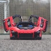
Eagle V2 an RC Trophy Truck [MOC]
Daniel-99 posted a topic in LEGO Technic, Mindstorms, Model Team and Scale Modeling
Hello, EuroBrickers! I am pleased to present to you the second version of my RC Lego Trophy Truck EAGLE. To be more specific, this is the third deep modification of the second chassis. Not surprising, as I've been working on this project for over three months now. For a better understanding of this topic it is worth reading about the first version. A better quality photos could be found on my BrickSafe. And a video: First looks: Features Independed suspension at the front with positive caster angle. 4-link solid axle suspension at the rear with anti-roll bar RC shocks (80 mm at the front and 110 mm at the rear) Brushless motor A2212 1200 kv for propulsion, Geek Servo for steering, 1500 mAh 3S Li-Po for power Strong and efficient transmission with metal U-joints and metal bearings. 95 mm RC wheels Light-weight bodywork Main goals "It's never a good idea to stop if you have something to improve." With these thoughts I was preparing a post about my Eagle a month ago. Here's a list of things I wanted to improve: Weight distribution: the heavy electronic components located in the cab loaded the front suspension more than the rear suspension. Rear axle geometry: due to triangulation on the rear axle, the driveshaft and lower suspension arms were located very high off the bottom of the truck, which limited the maximum compression angle of the rear suspension, and the entire chassis was not set to the horizon. Rear suspension setup: a true trophy truck requires a suspension with progressive stiffness. Front axle: steering was very sensitive, rather unusual front triangle shape and tilted lower suspension arms. Overall bulkiness of the chassis. Electronics The Eagle V2 utilizes the same electronic components as the Eagle V1. The story of my choice of such components is given in the post about Eagle V1. Therefore, I will be brief here. Motor: A2212 1200 kv Battery: 3S Li-Po 65C (30C is more than enough) 1500 mAh Controller: 2-3S 35A Transmitter: FlySky FS-GT5 Pros: Brushless motors last longer than brushed motors. High speed and torque in a compact size (about 3 BM in an XL motor) Radio control (best for fast RC cars) Cheap components (compared to Lego electronic components) available at local RC stores. External Li-Po battery allows for different layouts and unlimited power flow. Cons: Requires advanced techniques to build strong transmissions (requires lubrication) Otherwise can easily damage plastic parts. Not an easy decision for purists. Difficult to share instructions with others. Have to take care of tangling wires (same goes for large Lego-is designs). Non-universal solution, suitable mainly for RC Lego machines without a list of additional features. Frame & layout The Eagle V2 has a new "tube frame" (or chassis). This is why I decided not to call it a modification of my Eagle. Let's take a look at it from front to back. All important terms in this section are marked with bold text. In addition, this terms are highlighted on pictures. The front triangle uses the same "almost right" triangle with 14,15 and 6 stud lengths as the Eagle V1. The lower tube of the front triangle is made of two flip-flop beams that have been stacked together. This solution provides a sufficient level of stiffness and resistance to torsion. In addition, I was able to bring the suspension arm mounting points as close to the center as possible. The lower tube of the front triangle is adjacent to the flat bottom made of panels. The upper tubes of the front triangle intersect with the front wall. Further they pass into the side tubes of the cockpit. These tubes are made with flip-flop beams, which allowed me to secure them in place with a 15L front cross-brace (the Eagle V1 cockpit was 2 studs thinner). It's worth noting that the GeekServo motor squeezed perfectly between the lower front triangle tube and the cross-brace of the front wall. Thus, it practically reinforces the front triangle. The cockpit ends at the rear wall, which is reinforced by a rear triangle and structure around the transfer case housing. The side tubes pass into the rear H-tubes (horizontal). At the same time, the rectangular rear triangle is mirrored to form another rectangular triangle at the very back of the truck. The cross-brace on the rear wall is made using L-beams and 3D printed motor housing. Now let me describe the layout of the electronic components. Using a custom transfer case housing, I was able to move the brushless motor out of the cab. It is now located directly behind the rear wall. More importantly, I was able to move the Li-Po battery out of the cab. It is now located above the motor. It is true that this solution increases the center of gravity, but on the other hand it provides excellent weight distribution, which is very important for a trophy truck. The controller is located in the cab next to the driver's seat. Both battery and controller have no pin-holes, but I was able to fix them in place quite greatly. To load the rear axle even further, I added the spare wheel. Bodywork My main goals with bodywork of Eagle V2 were the following: keep it light keep the original shapes of Eagle V1 improve the proportions As a result I made the whole truck one stud longer and two studs wider than the first version. Now cockpit is wide enough to fit the driver`s seat. Also I changed the bonnet and the front grill. Finally I changed the very back of the truck to make it closer to real prototypes. I have to add, that not only the bodywork make the car look good. More importantly to keep the proportions in the chassis. The authentic look of the Eagle V2 is achieved with the proper settings of the suspension. Transmission I'd like to make a 3D model of my truck and show you a nice rendering of the drivetrain, like some great technical builders do. However, the Eagle V2 has a lot of custom parts and a bunch of "illegal" techniques like "almost rectangular" triangles. So I will just mark out the transmission components: Brushless motor with custom housing with planetary gear inside (1:4 gear ratio) Central transfer case with 28:20 gear ratio Rear differential with 12:28 gear ratio The transmission is built on carbon fiber axles and metal U-joints. It is separated from the frame by metal bearings. Metal bearings are used in the center transfer case, in the 5x7 frame that holds the differential, and in all the wheel hubs. I also lubed the planetary gear inside the engine case. Suspension geometry As I've said before, trophy trucks are all about suspension. So the main reason I did a V2 of my Eagle is to try and improve the suspension (both front and rear). Front suspension: Truth be told, not all custom parts turn out to be universal. On the contrary, the idea of efficiency in certain places and the idea of universality are not compatible at all. The Eagle V1 front wheel hubs are a prime example of this principle. They were originally designed for IFS street cars with smaller wheels. Therefore the basic ideas are present in their geometry: An inverted ball joint for the lower suspension arm (which is great in general). Combined with the tilted front suspension, they looked nothing like real trucks. The steering arms were 0.5 studs long, which resulted in very sensitive steering. I also didn't really like the 8 stud length suspension arms, which required custom of steering links to work properly. So I designed a new front suspension system that includes: 9 stud length suspension arms. New hubs (originally designed for live-axles) with 1 stud length steering arms. Thus hub does not use the ball joints! The new design is a deep modification of the Falcon trophy truck front suspension, which has proven to be reliable. In the V1, I used 8-studs suspension arms to fit within a certain chassis width and maintain a strong lower tube of the front triangle. However, by using stacked flip-flop beams, I was able to keep it 1 stud wide without losing stiffness. Rear suspension: It won't surprise you that the Eagle V2 has a new rear suspension. Here's a list of the changes: A new rear axle has been designed (again with a different set of custom hubs). It's more compact than the one the V1 had. The upper triangle of the suspension arms has been inverted (to match the real-world examples). New lower arms have been build. Now the live-axle was given the necessary degree of freedom. The attachment points for the suspension arms were lowered by two studs. This modification was possible due to the changes in the drivetrain described above. The anti-roll bar has been redesigned to match real prototypes. It resists to the twisting effect of the rear axle that appear in the acceleration. Shocks "Once a perfect suspension geometry is achieved, one may look for a proper set of shocks springs" The best springs Lego ever made are the hard 9.5 L springs, because they have a good amount of travel and responsiveness. For example, the 9.5 L soft shocks are not as good because the spring force has a hard time overcoming internal friction. On contrary, the 7L hard shocks have little travel and not enough stiffness to work properly with the hard springs. So I used 9.5L hard springs in the Eagle V1 and early versions of the second chassis. I tried to build a progressive rear suspension using Lego springs, but was not successful. The resulting design was either too unreliable or too bulky. I guess I lacked luck and skill, but I couldn't build a suspension that was both soft and shock resistant. It was either too stiff to absorb big bumps or too soft. So I decided to use RC shock absorbers to properly address this issue. RC shock absorbers have different springs that allow you to adjust SAG and progression without having to move the shock absorber mounting point along the suspension arm. I once tried to adapt RC shock absorbers to Lego, but couldn't find a suitable way to attach them to the Lego pins. Fortunately, a working solution was offered by Ryokeen in his Generic Brushless Trophy Truck. I again had to modify the chassis to fit 1:10 scale RC shock absorbers. Front suspension has 80 mm shocks with 2.5 studs travel. I mounted it behind the suspension arms as it is done it real Trophy Trucks and many RC scale models. There was a way to place it through the upper A-arm, but such solution required 4L liftarms. In addition it had not freedom in the choice of mounting points. Rear suspension uses 110 mm shocks with approximately 3 studs of travel. Additionally they have a dual spring setup, which give the desirable progressive hardness to the rear suspension. Again, I tried to mount rear shocks in the same way it is done in real Trophy Trucks. Developers diary. 3-7 Sep An Eagle V1 was finished. The driving tests started. Front wheel hubs are the same as in Hornet 4x4 Buggy. 11-15 Sep The new front triangle has been built. Now truck has a tilted lower tube and positive caster. The differential has been changed from yellow to red one. 17 Oct I stated developing a new chassis with a different set of ideas behind. (mostly with the triangulation in the rear axle removed and central transfer case added). 24 Oct First prototype of the new chassis has been built. In addition to the redesigned rear axle, I made a new front axle with a shock coming through the upper A-pillar. 27 Oct I started building a bodywork for a new chassis. 1 Nov The first modification of the second version of Eagle has been finished. I started the driving tests. The rear suspension has a new idea if mixing anti-roll bar with additional shocks to achieve progressive suspension hardness.... that was a total madness... 8 Nov The whole chassis has been widened by 2 studs for better proportions. 14 Nov A new rear suspension ideas has been applied. The back of the Truck has been changed. Now the rear suspension has two sets of hard 9.5L springs on each side. Progressive stiffness... Bulky realisation. 25-28 Nov RC shocks has been added. For that reason both front and triangles has been redesigned. -
Simple Off-Roader + Instructions
Daniel-99 replied to Zerobricks's topic in LEGO Technic, Mindstorms, Model Team and Scale Modeling
A good car for a wide technic community! Thanks for sharing! -
[MOC]Generic brushless Trophy Truck
Daniel-99 replied to Ryokeen's topic in LEGO Technic, Mindstorms, Model Team and Scale Modeling
Hey, man! I love to see the progress on this project. Whole chassis become cleaner and properly-designed! Keep up!