Search the Community
Showing results for tags 'control'.
Found 36 results
-
[WIP] A novel 3D printed Lego mini motor for the PF system
896gerard posted a topic in LEGO Technic, Mindstorms, Model Team and Scale Modeling
For long, I've wanted a small strong mini Lego Technic motor, smaller than an M-motor. As I recently learnt how to draw Lego parts and had the opportunity to use 3D printed nylon (using laser sintering) , I decided to try a small motor as well. As the PU motor stuff is getting big and heavy, this is my response: a small easy-mountable motor with a case of only 5 by 2 by 2 studs. 70% of the motors in Lego Technic models don't have to be large. Only the mount of this tiny motor is 2x3 studs. The mount is tailor made for Technic applications: if you build often with M-motors you will know that an M-motor always must be connected to a 1L beam to ensure that the gears won't slip and to mount the M motor securely. The mount design of this new motor eliminates the need for the beam, so that's one stud saved already. Because the motor is only 2 studs wide, 3 mini motors can be in the space of 2 M-motors. Also, 3 mini motors take up the space of one XL motor.. The exterior design is derived from a PF M-motor, because I like the design and want to keep using the PF looks. This is still a work in progress as I need to mount a 9V connector and insert the inner electric motor(already in stock here). I also need to do some more painting and sanding. Nonetheless, the printed parts are quite accurate. I will give an update soon when the motor is working. The motor gets internal electrics that work up to 12V so also third party remote control bricks will be allowed to use their boost modes. My big hope is that TLG understands that we need small motors and remotes, not big ones. The length of 5 studs makes this motor very easy to put in all kinds of leftover spaces. Thanks for reading. I'm open to design improvements! -
Offroad Vehicle Design bible
Zerobricks posted a topic in LEGO Technic, Mindstorms, Model Team and Scale Modeling
I started this project because I wanted to share my experiences building various offroad models over the last decade. This topic is meant to guide the builders with comparisments, suggestion and best building practices, It is however not a place to find already finished and perfected designs - that's up to you. Various aspects of the design of the vehicles will be split into several subgroups and explained in details. 1. Number of wheels First thing we need to know is how many wheels our design will have. Most common setups are as following: 4x4 Setup Advantages: 1. The simplest and most widely setup 2. Having only 4 wheels means lower weight and higher performance 3. Higher manoeuverability 4. Simple suspension and driveline design Disadvantages: 1. With only 4 wheels the suspension has to be designed to be as flexible as possible to get the most out of the wheels 2. In a case of a mechanical failure of a single wheel, the whole model's performance is greatly affected 6x6 Setup with double rear axles Advantages: 1. Two rear axle provide more traction area, especially when going uphill 2. Usually 6x6 vehicles are longer than 4x4 and therefore less likely to tip over 3. Since the front and second axle are usually closer than in 4x4 setup, there is less ground clearance needed between them 4. Greater redundancy in a case of a mechanical failure Disadvantages: 1. Lower manoeuverability due to a longer wheelbase even with rear wheel steering 2. More complex driveline and suspension design is required 8x8 or more wheels setup Advantages: 1. Having 8 or more allows for much greater traction area 2. Ability to drive over ditches 3. Because wheels are usually much closer there is much less chances of getting stuck on top of an obstacle 4. Excellent redundancy in a case of a mechanical failure 5. Better weight distribution 6. Less suspension travel required per each wheel as with 4x4 or 6x6 and hence better stability Disadvantages: 1. Lower manoeuverability even with rear wheel steering 2. Powering 8 or more requires a very complex driveline 3. Depending on a driveline, combined torque required for powering all 8 wheels can destroy gears if a single wheel gets stuck 2. Type of wheels and tyres Now that we decided on how many wheels we want for our offroad beast, we have to look into what type of tyres and wheels we want to use. I will hereby cover only the bigger types of tyres and wheels. 1. 94.8x44R Advantages: 1. Low weight 2. Good thread design 3. Low rolling resistance Disadvantages: 1. Low traction, these tyres are prone to slip on the rim at high loads 2. Due to its rounded shape the tyres tend to slide off obstacles when crawling over them 2. 94.3x38R Advantages: 1. Low weight 2. Medium traction 3. Low rolling resistance 4. Realistic design and proportions Disadvantages: 1. Shallow thread pattern 2. These tyres are very hard and don't adjust to the terrain 3. 107x44R Advantages: 1. Low weight 2. Medium traction 3. Very deep thread 4. Currently largest tyres by diameter Disadvantages: 1. High rolling restistance and vibrations due to the thread pattern 2. These tyres are a bit hard and don't adjust to the terrain 4. Power Puller tyres Advantages: 1. High traction 2. Good thread 3. Largest Lego tyres ever produced 4. Deep wheel offset Disadvantages: 1. High weight 2. Hard to use, they require complex hub assemblies 3. Very rare and expensive 5. Outdoor challenger wheels Advantages: 1. Very high traction 2. Very good thread pattern 3. Deep wheel offset 4. Over 7 studs of space inside the wheel Disadvantages: 1. High weight 2. Hard to attach to the standard axles 3. They require a lot of torque to use them at their full potential. 6. Tumbler wheels Advantages: 1. Low weight 2. High traction 3. Very flexible Disadvantages: 1. Low thread pattern 2. Small size 3. Expensive For the 94.8x44R. 94.3x38R and 107x44R tyres we have a choice of two wheels: 1. Racing wheel large Advantages: 1. Good mounting option with axlehole and pinhole 2. Available in multiple colours 3. Cheap Disadvantages: 1. No inside wheel offset means steering pivot point can't be placed inside the wheel. 1. Futuristic wheel Advantages: 1. Deep wheel offset allows us to place steering pivot point inside or closer to the wheel than racing wheel large 2. Slightly larger wheel size stops the 94.8x44R tyre from slipping on the rim Disadvantages: 1. Limited mounting options, with only one axlehole 2. Hard to find 3. Hubs Now that we have our wheels and tyres we need a way to mount and power them. Here are the most common currently available options: 1. New standard ungeared CV hubs These hubs are usually driven by the CV joint counterpart which pops inside Advantages: 1. Low steering pivot offset - usually at the edge of the tyre: 2. Firm wheel mounting 3. Readily available, easy to use and to build on. Disadvantages: 1. Low operating angle - the CV joint can operate to a maximum of about 30 degrees, which limits steering angle. 2. Very low torque transfer - the CV joints are prone to deforming and popping out even with low torque applies to them 3. Low ground clearance 2. Old ungeared CV hubs Advantages: 1. Low steering pivot offset - usually at the edge of the tyre 2. Firm wheel mounting 3. Better ground clearance than newer hubs Disadvantages: 1. Very low operating angle - the CV joint can operate to a maximum of about 25 degrees, which limits steering angle. 2. Very low torque transfer - the CV joints are prone to deforming and popping out even with low torque applies to them 3. Hard to find and expensive 4. No other mounting points than 4 ball joints 3. Built cardan ungeared hubs Example of a hub using a cardan joint to directly transfer the power to the wheel Advantages: 1. Low steering pivot offset - usually at the edge of the tyre 2. Easy to build 3. Can transfer higher torque than a CV joint 4. Higher steering angle Disadvantages: 1. Mounting relies only on the axle and is not as firm as standard hubs 2. Not capable of transferring high torque to the wheels 3. Low ground clearance 4. Standard portal hubs Advantages: 1. Easy to use and to build on. 2. Can transfer very high torque to the wheels when using 8z and 24Z gear combination 3. High steering angle 4. High ground clearance 5. Firm wheel mounting Disadvantages: 1. Very high steering pivot offset - requires stronger steering mechanisms and more fender space for wheel to swing 5. Built portal hubs Advantages: 1. Easy to build. 2. Can transfer very high torque to the wheels when using 8z and 24Z gear combination 3. High steering angle 4. Higher ground clearance than standard portal hubs 5. Low steering pivot offset when using futuristic wheels Disadvantages: 1. Wheels are mounted and held only by one axle, not as firm as standard hubs 2. Hub relies on friction of the components to keep it together, which can slide apart after prolonged use 6. Built planetary hub Advantages: 1. Highest gear ratio of all other hubs, 1:4 2. Firm wheel mounting when using futuristic of power puller wheels 3. High steering angle 4. Lower steering offset than standard portal hubs Disadvantages: 1. Requires old turntable, futuristic or power puller wheels for best results - all are hard to find 2. High number of moving gears 3. Least efficient due to the high friction caused by the large surface contact area and number of moving gears 4. Suspension Suspension is the mechanism that will keep our model's wheels in contact to the ground and will be supporting most of its weight. Most of the designs cover 4x4's Following factors determine the type of suspension system we will use: 1. Weight of the model - The heavier the model, the stronger the suspension components have to be 2. Speed - Faster models require more responsive suspension systems with low unsprung weight 3. Flexibility - The higher the obstacles you want to climb over the more flex and/or wheel travel suspension has to provide 1. No suspension I have yet to see and offroad vehicle without any type of suspension (except for maybe 42070, 42081 and 42082), but I will list my opinion regardless: Advantages: 1. Simple design - having no suspension simplifies our design...and that's about it Disadvantages: 1. No flex over terrain means, there are only 3 wheels at once touching the ground 2. Low stability 3. Poor weight distribution 4. No shock absorption at high speeds 2. Pendular suspension This is the simplest suspension you can put on your vehicle. It basically means one or more of your axles are free to swing about. When using this suspension I suggest using the small turntable where drive axle enters the axle. This will keep the drive axle from carrying the weight of the model, which causes unnecessary friction. 42030 is a typical example of this suspension system. Advantages: 1. Simple, robust design 2. Using this suspension on both axles can give the model very high flexibility 3. If there are no springs used, the model can have perfect weight distribution on left and right wheel Disadvantages: 1. Large unsprung weight, poor responsivness at high speeds 2. No shock absorption means this suspension is not suitable for high speeds 2. When using on one axle, the stability of the whole model relies on the unsuspended axle. 3. When using pendular suspension on both axles springs or a transfer mechanism are required to keep the model upright 3. Single torque tube suspension This suspension became available with the release of the 8110 Unimog. Best examples of this suspension are 8110, 9398 and 41999. It is the simplest suspension which also allows for vertical suspension movement. Advantages: 1. Simple, robust design 2. Universal joints can be placed inside the ball joint, allowing power to be transferred to the axle 3. Easy to implement Disadvantages: 1. Large unsprung weight, poor responsivness at high speeds 2. Axle requires a some kind of a linkage system to keep it cenetred (panhard or parallel links as seen above). 3. Using this suspension on the front axle usually results in negative caster angle which causes higher rolling resistance 4. When used on rear drive axle, the suspension has the tendency to cause oscillate, especially with soft suspension and high power 4. Hard to connect springs to the chassis 4. Double torque tube suspension This is an evolution of the single torque tube suspension, which uses two ball joints to drive each wheel side respectively. It is my own original idea. Advantages: 1. Simple, robust design 2. Universal joints can be placed inside the ball joint, allowing power to be transferred to the axle 3. Easy to implement 4. Self-cenetring, since axles are connected in the center there is no need for linkages to center it 5. Can carry power to each wheel side independently 6. Drive torque compensation Disadvantages: 1. Large unsprung weight, poor responsivness at high speeds 2. Using this suspension on the front axle usually results in negative caster angle which causes higher rolling resistance 3. When used on rear drive axle, the suspension has the tendency to cause oscillate, especially with soft suspension and high power 4. Hard to connect springs to the chassis 5. Parallel floating axle This suspension uses linkages which keep the axle parallel to the chassis of the model. For best functionality and reliability the lengths of all links and that of the double cardan joint should be equal. Also all the linkages and drive axles should be parallel. Advantages: 1. Keeping the axle parallel to the chassis reduces the oscillations effect 2. Better responsivness compared to the torque tubes 3. Neutral caster angle when used on front axles. 4. Self cenetring when using A arm as upper link or 4 link setup 5. Can be configured to carry power to each wheel side independently 6. If configured to carry power to each wheel side independently the drive torque can be compensated. 7. Easy to connect spring to the chassis Disadvantages: 1. High unsprung weight, less responsive at high speeds 2. Increased mechanical complexity, double cardan joints required to carry the power to the axle 6. Half axle independent suspension This is the simplest independent suspension you can build. Best example of such suspension are Tatra and Pinzgauer trucks. Advantages: 1. Independent suspension with low unspring weight, suitable for high speed 2. Robust design with low number of moving parts 3. Easy to connect spring to the chassis Disadvantages: 1. Changes of the caster angle as the wheels travel up and down 2. Hard to implement a drive system that does not carry the weight of the vehicle 3. Hard to implement steering system 4. Wheels tend to drag sideways on the ground when suspension travels up and down, reducing efficiency 7. Trailing arm parallel independent suspension Personally I have not used this suspension yet, but I did use a normal trailing arm suspension which does not keep the hubs parallel. Normal trailing arm suspension which does not keep the hubs parallel acts similarly to torque tube suspension. For the prallel version of the trailing suspension I imagine the following: Advantages: 1. Independent suspension with low unspring weight, suitable for high speed 2. Robust design with low number of moving parts 3. Long links allow for high suspension travel 4. Very easy to connect spring to the chassis 5. Can be configured to carry power to each wheel side independently Disadvantages: 1. Hard to keep the wheels from sagging under the weight of the model. 2. Difficult to transfer power to the wheels 8. Double wishbone suspension This suspension uses two A-shaped arms to keep the wheel hubs in place. As of late it's my favourite suspension system due to: Advantages: 1. Independent suspension with low unspring weight, suitable for high speed 2. Very customizable design with lots of adjustable characteristics (suspension arm lengths, caster angle, camber angle, steering geometries) 3. When build correctly it is far more robust than live axle suspension 4. Increased ground clearance compared to live axle suspension, especially when used with portal hubs 5. Can be configured to carry power to each wheel side independently 6. Extremely easy mounting of springs 7. Very stable compared to live axles 8. Frame holding the suspension can be part of the chassis, therebye lowering the center of gravity Disadvantages: 1. More moving parts as live axle suspension, increased mechanical complexity 2. Limited wheel travel - Lego wishbones allow a max. of around 25 degrees of suspension angle 9. Multi-link suspension To be updated when I build my first multi-link offroad suspension. I can assume the following characteristics: 1. Independent suspension with low unspuing weight, suitable for high speed 2. Extremely customizable design with lots of adjustable charactersitics (suspension arm lengths, caster angle, camber angle, steering geometries, virtual pivot point) 3. Large steering pivot point compensation 4. Increased ground clearance compared to live axle suspension, especially when used with portal hubs 5. Can be configured to carry power to each wheel side independently 6. Very stable compared to live axles 7. Frame holding the suspension can be part of the chassis, thereby lowering the center of gravity Disadvantages: 1. Very high amount of moving parts, increased mechanical complexity 2. Limited wheel travel - Lego wishbones allow a max. of around 25 degrees of suspension angle 3. Hard to connect springs to the chassis 10. Spring types Listed below are the most common types of springs available: 6.5L Soft shock absorber Advantages: 1. Small, easy to implement Disadvantages: 1. One stud of suspension travel 2. Low spring rate, can't support heavy models 6.5L Hard shock absorber 1. Small, easy to implement 2. High spring rate, can support heavy models Disadvantages: 1. One stud of suspension travel 9L soft shock absorber When using 9L shock absorbers I suggest you do not use the default offset upper attachment point, but use an in-line attachment point instead. This will reduce the friction and allow for better high speed performance Example: Advantages: 1. Two studs of suspension travel 2. More attachment possibilities than 6.5 L shock absorber Disadvantages: 1. Default attachment points create friction 2. Low spring rate, can't support heavy models 9L hard shock absorber Advantages: 1. Two studs of suspension travel 2. More attachment possibilities than 6.5 L shock absorber 3. High spring rate, can support heavy models Disadvantages: 1. Default attachment points create friction 2. Rare and expensive 11. Attaching springs to live axles If we start with basics, the first things we have to check is how position of springs affects suspension of live axles. The closer you place the springs together, the more flex the suspension will have, but it will also be less stable: I suggest you to keep springs at a distance of around 1/2 of the total model width. When placing springs you should keep them in-line with the wheel bearing in order to reduce friction. First example of bad spring placements: And example of good spring placement: When using multiple springs make sure to place them symmetrically centrred to the wheel hub: When attaching springs to torque tube suspension, you have to allow springs to tilt in two planes: You can also attach the springs to the suspension links to increase suspension travel. This technique is especially common on Trophy Trucks: 12. Attaching springs to independent suspension Independent suspension allows for much more flexible spring placement. Generally the closer you attach the spring to the main suspension arm pivot, the higher spring travel you get, but lower suspension force. Examples going from the hardest suspension with low travel to the softest with high travel: You can also attach springs inside the suspension arms: Or horizontally: As with the live axles make sure springs are in the center of the wishbones. Example of good placements: And an example of bad spring placement, which causes excessive friction and suspension binding: 5. Steering Steering is the system which allows our model to change direction. Generally there are two types of steering system used: 1. Skid steering Advantages: 1. Very simple to implement and control with two separate motors for left and right sided wheels. 2. Does not require a dedicated steering motor Disadvantages: 1. Not efficient, since wheels have to skid to steer 2. Power had to be reduced or even reversed in order to steer. 3. Not very accurate 4. Not very effective offroad 2. Classical steering with steerable wheels Advantages: 1. Efficient, with minimum loss of speed 2. Accurate 3. Does not reduce the power of the drive motors 4. Can be used in front, rear or all axles for tight steering radius or crab steering 5. Effective offroad Disadvantages: 1. Requires more complex hub assemblies 2. For best steering accuracy you need a dedicated servo motor. Examples of a simple classical steering system for live axles 1. Parallel steering system for live axles Here both hubs are always parallel. Position of the steering in the front or rear rack has no affect on the steering. Advantages: 1. Very simple and robust 2. Easy to build Disadvantages: 1. No Ackermann steering geometry 2. Steering rack moves inwards as it steers, requiring more space. 2. Ackermann steering system for live axles This system allows the hubs to steer at different rates. The steering arms are offset inside so they form a virtual steering point where at the point where lines meet. Advantages: 1. Better steering performance Disadvantages: 1. More complex assembly 2. Steering rack moves inwards as it steers, requiring more space. 3. Steering system with diagonal linkages This system acts similar as Ackermann steering system by using diagonal steering links. Advantages: 1. Better steering performance 2. Steering rack only has to move in one direction without sideways movements 3. Can be configured to be used in front or the rear of the axle. Disadvantages: 1. More complex assembly 4. Simple steering system for independent suspension 1. Very simple and robust 2. Easy to build 3. Can be even more robust when using double steering racks and links 4. Steering rack only has to move in one direction without sideways movements Disadvantages: 1. No Ackermann steering geometry 5. Ackermann steering system for independent suspension Advantages: 1. Better steering performance 2. Steering rack only has to move in one direction without sideways movements Disadvantages: 1. More complex assembly, less robust. 3. General steering tips 1. When using independent suspension always make sure your links are paralel to the suspension arms, otherwise you may end up with wheels which are not parallel and are causing excessive friction: 2. When using standard portal hubs make sure your steering system is robust enough to deal with the forces generated by wheel driving into obstacles. 3. If possible use servo motors which allow for high steering precision and return to center. They are especially useful at high speed models. 4. Most efficient way to steer the wheels is using the steering racks. 5. Build axles in such way they have positive caster angle, example for direction of travel from right to left. This will self-center your wheels and reduce rolling resistance. 6. Drivelines Drivelines are the responsible for transferring the power from the motors to the wheels. There are various drivelines you can build, here I listed few with their characteristics: Driveline types 1. Permanent 4x4 Advantages: 1. Simple, centralized, low mechanical complexity 2. Wheels are always powered, great offroad performance 3. Light weight Disadvantages: 1. Poor steering radius 2. Tyres have to skid when steering, lowering efficiency of the model 2. 4x4 with open differentials Typical example of this driveline is 42070 Advantages: 1. Differentials allow the wheels to so spin at different rates when steering 2. Very efficient since wheels don't have to skid when steering Disadvantages: 1. If one wheel loses traction, all the power is transfereed to it, poor offroad performance 3. 4x4 with lockable differentials Advantages: 1. Differentials allow the wheels to so spin at different rates when steering 2. Very efficient since wheels don't have to skid when steering 3. All differentials can be locked, so wheels are powered for great offroad performance Disadvantages: 1. Higher mechanical complexity 2. Dedicated motor is required to actuate differential locks, higher weight 4. Axle mounted motors Typical example of this driveline are 9398 and 41999. Advantages: 1. Differentials allow the wheels to so spin at different rates when steering 2. Very efficient since wheels don't have to skid when steering 3. If one wheel gets off the ground the second axle can still pull/push the model. Disadvantages: 1. Higher mechanical complexity 2. Usually the rear axle motor is more loaded than the front, especially when climbing uphill, the motors can't "help" each other. 3. Worse offroad performance than permanent 4x4 5. H drive: This is my favourite driveline due to the following reasons: Advantages: 1. Motors allow the wheels to so spin at different rates when steering 2. Model can skid steer 3. Very efficient since wheels don't have to skid when steering normally 4. Having 2 drivelines allows you to carry more torque to the wheels 5. Redundancy, even if one drive fails the model can still move 6. Wheels are always powered, great offroad performance Disadvantages: 1. Higher mechanical complexity 2. Slightly higher weight 6. Wheel motor drive Each motor powers a wheel independently. Advantages: 1. Motors allow the wheels to so spin at different rates when steering 2. Model can skid steer 3. Very efficient since wheels don't have to skid when steering normally 4. Redundancy, even if one or more motors fails the model can still move 6. Lower mechanical complexity Disadvantages: 1. Motors can't "help" each other 2. Higher weight due to a higher motor count Transferring power axially When transferring power via axles, you can reduce the flex by using connectors instead of simple "bare" axle: Use axles with stops to prevent them from sliding out of gears: Where possible always brace tooth gears from both sides: Transferring power at an angle Where pairs of U joints are used, make sure to align them to eliminate vibrations: Brick built CV joint which can transfer high torque at over 30 degrees angle Brick built cardan joint which can transfer extremely high torque up to 15 degrees angle Brick built flexible drive which can transfer medium high torque, extract and retract, suitable for low angles Transferring power perpendicularly The following perpendicular gearboxes are the best suitable for transferring high torque Avoid knob and worm gears, because they waste energy Gearboxes In my models I generally use the following gearboxes: 1:3 differential gearbox Advantages: 1. Very high gear ratio between low and high gear, 1:3 2. Capable of transferring high torque 3. Very efficient since only 2 gears are used at any time Disadvantages: 1. Takes a lot of space 2. This gearbox requires a good housing to brace the gears properly Compact two speed gearbox Advantages: 1. High gear ratio between low and high gear, 1:2,77 2. Capable of transferring high torque 3. Very efficient since only 2 gears are used at any time 4. Very compact design Disadvantages: 1. Requires two of the rare 20 tooth clutch gears 2. More complex shifter assembly. Diagonal gearbox Advantages: 1. High number of gears 2. High gear ratio possible, over 4:1 2. Capable of transferring high torque 3. Very efficient since only 2 gears are used at any time Disadvantages: 1. Takes a lot of space 2. Input and output axles are not parallel. 3. A complex shifting assembly is required for sequential operation. Driveline effect on suspension Transferring torque on the wheels can affect the suspension, especially when live axles are used. The following photo shows how the torque causes one side of the axle to push down and the other to lift up: In order to minimize this effect I suggest the following: 1. Make sure to have most if not all the downgearing inside the axles, so you do not need high torque going to the axles. 2. Make sure your models have a low center of gravity 3. You can eliminate this effect by using two counte rotating axles which cancel each other's torque, example below: 7. Motors and control Following are the most common types of motors used for Lego models. You can find more info here: http://www.philohome.com/motors/motorcomp.htm My personal favourites are L and RC motors due to the balanced output speed to torque ration and great mounting options. 1. PF-M Advantages: 1. High speed output 2. Smallest available motor 3. Cheap and available Disadvantages: 1. Low torque 2. Poor mounting options 2. PF-L Advantages: 1. High speed output 2. High torque 3. Cheap and available 4. Great mounting options Disadvantages: 1. Odd shape 3. PF-XL Advantages: 1. Very high torque 3. Cheap and available 4. Good mounting options Disadvantages: 1. Slow speed output 2. Large form factor 4. PF-Servo Advantages: 1. Very high torque 2. Very precise output with 15 positions 3. Good mounting options Disadvantages: 1. Slow speed output 2. Output axle can move a max of 180 degrees 3. Large form factor 4. Hard to find 5. 9V-RC motor Advantages: 1. Most oowerful Lego motor 2. Very high speed output 3. Good mounting options 4. Two output axles with different gearing ratios 5. Drive axles can pass through the motor Disadvantages: 1. Low output torque 2. Low efficiency 3. Power hungry 4. Odd form factor 5. Hard to find and expensive Power options 1. PF - AA battery box Advantages: 1. High capacity 2. Good mounting options 3. Works with rechargeable batteries, but with lower performance 4. Cheap and easy to find Disadvantages: 1. 750mA current limit - not enough to fully power RC motor 2. Heavy 3. Has to be removed and opened to replace batteries 4. Wasteful 5. Odd form factor 2. PF - LiPo battery box Advantages: 1. Small form factor 2. Light weight 3. Easy to recharge Disadvantages: 1. 750mA current limit - not enough to fully power RC motor 2. Low capacity 3. Studded design 4. Expensive and hard to find 3. RC control unit Advantages: 1. No current limit - can power 2RC motors at once 2. 3 Power levels 3. Has integrated steering output with 7 positions 4. Good mounting options 5. Easy battery replacement 6. Radio based control Disadvantages: 1. Poor quality, prone to breaking 2. Limited angle (45 degrees) and torque from the steering output 3. Has to be removed and opened to replace batteries 4. Very large form factor 5. Expensive and hard to find 6. Heavy 7. Required dedicated antennas and remote Control options 1. PF receiver and controller Advantages: 1. Receiver is easy to integrate into the model 2. Controllers have physical feedback 3. Cheap and easy to find Disadvantages: 1. IR based, low range, useless outside 2. Lack of PWM motor control, unless using train controller which is awkward to use 3. Odd form factor for use with steering 2. RC control unit See above 3. Third party options such as BuWizz and Sbrick Advantages: 1. Smaller form factors, easy to integrate into model 2. More outputs than PF system 3. Smooth control of motors 4. High range thanks to Bluetooth control 5. Higher power available with BuWizz 6. Customizable profiles Disadvantages: 1. Smart device is required 2. No physical feedback 3. Sbrick is limited by PF battery box 4. Price 8. Chassis Chasis is the backbone of your model which olds everything together. For chassis I suggest you to use the following components in order to make it strong and robust enough to deal with the stresses involved when crawling or driving at high speed: Some flex in the chassis might be a good thing to improve offroad capability, but only if id does not affect the driveline and cause friction on the drive axles. Remeember to use diagonal support, since triangles are the strongest shapes. You can also use panels and motors as structural support. Interlocking your chassis will keep it from slipping apart. For good examples of chassis designs I suggest you check the instructions for 9398 and 42083. -
 The last years, we have used a NXT brick for controlling the train. For Lego World 2017, we want to use EV3 bricks only. Since the RFID sensor is not supported anymore, we needed another way to determine the train location. I have build a proof of concept of a loco: Wheels are directly connected to a EV3 medium motor Location detection based on a color sensor (the combination of yellow, red and green makes a unique pattern) And it works fine! A video of this proof of concept: Of course, the train needs a bit (... ) of restyling ;-) Enjoy, Hans
 -

New version 1.0.0 of Legoino Arduino library
Cornelius posted a topic in LEGO Technic, Mindstorms, Model Team and Scale Modeling
I am very happy about all the feedback and contributions which take the library to that step. Today version 1.0.0 of the legoino library is released! After over a year of learnings and feedback i have reworked the library to be more consistent and to make some things easier. Unfortunately this was not possible without breaking changes. This means some functions and methods has to be removed or renamed. To make the migration of your sketches easier, just have a look into the Migration guide provided on the github project page: Migration guide New features Duplo Train support Enriched Motor commands (maxPower, brakingStyle) Support of setAbsoluteMotorPosition, setAbsoluteMotorEncoderPosition Callbacks for changes on hub properties and sensor values PowerFunction (IR) functions included Hub Emulation (powered up to powerfunction translator) Adding of getHubName rework of log messages to the standard log_d, log_w, log_xx messages. Log levels could now be switched via the Arduino environment Contribution I am very happy about the whole community who participates in that library and contributes with ideas and your cool projects that uses the legoino library. If you have any questions, ideas or need help, you can just contact me. Looking forward to all the cool stuff you are building with the new version of the library. Cheers, Cornelius -
Hello My first post here. Found some posts regarding the comparison of Powered Up (PU) and Power Functions (PF), but it was rather related to Technic. Couldn't find any similar for trains. So I am considering to buy 60198 Lego Cargo Train which is powered by Powered Up. However, I read here about PU system that it is inferior to PF system, as considering it in LEGO Technic. So how it is in the Trains department? As far as I see: PF for trains has remote IR intutitive controller with two knobs; for A channel and B channel with max. 8 trains to control (with 4 controllers). Additionally battery box and seperated IR recevier is needed. PU has bluetooth remote controller, so clunky smartphone control can be omitted? But is PU remote controller in any point inferior to older PF controller? PU battery box has embedd bt receiver so less space is needed inside the locomotive, so it seems its better (less flexible though?) Coming back to 60198 buying consideration; I saw some offers of used PF systems for trains (separated or with a locomotive), but they are quite pricey: 55 EU for control set, and 100EU with control+locomotive (from 60052 or 7939 set). So is it better to buy this new set with PU or invest into older used (but better?) PF sets? Kind regards
-
When I stumbled across Paint0r's Legos Ideas page for a Lucrehulk-Class Droid Control ship, I had to build it. So I did. Please support Paint0r's build if you can. The Lucrehulk was a dream addition to my display for some time, and I don't think TLG will ever sell one. So when I saw this design I knew the wait was over - except for ordering the additional 1200 pieces I needed for the build. It took a few nights to figure out how many of the 1695 pieces I had already. These photos were taken at a point where I'd color swapped enough of the ship for display purposes. I didn't follow the .LDD instructions perfectly because there were a few points where I'd gotten lost or simply didn't have the pieces. However, the approach to the build was repetitive, so I was able to 'fill in the blanks' when needed. The Pick-a-Brick order was nearly perfect - but I'd ordered 96 of a slope 45 1x2 with plate and it came in white instead of light grey (a piece that PaB doesn't have available in light grey). I was pretty disappointed until I started building it anyway and thought a dash of white was okay. I also spashed a bit of Trade Federation blue in there, too. This now means, of course, this isn't the ship from The Phantom Menace, the Vutuun Palaa. Another ship of it's class, further along in The Clone Wars. The build: it was a lot of similar wedges. Started with the core, of which I had enough grey laying about to assemble it. It does disconnect from the base model fairly easily. I do hope that if Paint0r sees this model, they aren't disappointed with some of the many cosmetic deviations I made from the original model. I'd say I'm 90% accurate to the instructions, and the final build of the design which was shared here. Much of it was limitation of my patience and budget. It's very difficult to get the arms of the hangars to align perfectly (can see this in the top view photo below). It takes some doing to squeeze the wedges together to make a smooth curve... and sometimes results in buckling and the pieces go flying... argh. As a result, these initial photos will be updated once I can get the twin hangars more symmetrical. It takes patience. But having this beast on display is worth it... even if it isn't swooshable. I really skimped out on the engine array. Too many pieces hard to find on Pick-a-Brick and it was just easier to stick the sub-engines to the side of the hull rather than build the intricate lattice that holds the three main engines and six sub-engines together. I am satisfied with the way it looks. This build will be the centerpiece of my Trade Federation army someday. Will need a little micro-scale fleet of N1 fighters too, of course to bring it down. Front view Top view Antenna array Hangar detail Core view Engine array Ready for display Side view of the core and how it attaches to the main frame of the ship. Wedges aplenty! Most of the build was creating ten of these very tightly packed, extremely well designed wedges that comprise each of the cargo bay/arms.
-
Can I get advice on the new Powered up system? I am not building any particular Lego sets. I just make them up as I go along. I recently bought on Ebay motor 88014 not realising it couldn't be connected to existing "old-style" battery boxes. So I then bought a new-style battery box (88012) but that doesn't have any switch control. Various sites (including Lego's own) talk about using the app to code instructions, but I don't want to do that (yet; may come on to that later). For the moment, I just want start, stop and reverse. So my question is what do I need now to make that happen? If I get the remote (88010) will that be all I need or is there something more? The battery box I have ( 88012 ) has 4 connections, identified A - D, but the remote only seems to have two, so how does that work? Any advice greatly received. My own childhood was spent with Meccano, but came to Lego with my children. Now, after a 30 year gap, I have dug out the Lego again for the grandchildren but things have changed during those 30 years! It also seems that unless you start off by buying a complete set, then Lego itself isn't very interested in helping you. Templar
-
Hi. I would like to make a shout out for this company: http://www.aquabrixel.com/_en/ They have launced a fluid pump compatible with Lego pneumatics. Does anyone have experiences with them? http://www.aquabrixel.com/img/pump_video3.mp4 I really like the idea as it is something I always have considered trying to make the pneumatic system less jerky. I would however use a thin silicon oil rather than water... -ED-
-
Good evening together, Today i have a question to the community. For a new idea i have to collect some further information about the train remote-control 64227. I know there are around 14 steps to control the speed of a train. -7 => +7 (seven reverse and seven forward). But how many degrees will i turn the wheel from -7 to +7? I know it´s endless and in most cases it doesn´t matter, but in this special case i need to know as exact as possible. Does anybody know the degree per step too? With kind regards Martin
-
HI, I wonder if anyone has some experience with using buwizz with Lego trains? I am attracted by the small form factor and the opportunity to design profiles, but over 120 Euros is a lot to risk without asking advice here ...
-
[MOC] Lego ~Technic Camera boat | filming from the surface
896gerard posted a topic in LEGO Technic, Mindstorms, Model Team and Scale Modeling
Once in a while, every Technic builder wants to build a Lego boat. I was no exception, but there's a lots of boats being built: how to make an original boat then? I decided to not design a good-looking boat, but to make it a tool for filming. This choice asks for a boat that can be quickly placed into its filming position, which means it should be fast and agile. It should also have enough remote control range to film on big water areas. The 1980's Power Functions remote is thus completely out of the question: responds very slow and outside, there's 2 metres of range. We all must thank S-brick for existing. S-brick (or alternatives) makes this boat possible: without sufficient range, there cannot be a camera boat. Many boats have a keel and a rotating propeller at the back. A submerged plane behind the propeller acts as a rudder. Sadly, a rudder becomes less efffective at lower boat speeds and the boat reacts slowly to it: turning the rudder does not mean turning the boat, it first needs speed (and thus space!) to turn. In Dutch ditches (where I wanted to test the boat), there is not a lot of space available for maneuvering. Having a a slow-responding boat with a rudder there means the boat being into the reed all the time. I therefore eliminated the rudder and mounted the propeller on a hinge. Any hinging of the propeller system at any propeller speed the boat causes immediate turning, which is a nice direct response on the steering input. Good theory, but when a single rotating propeller is mounted on the rear, the boat will rotate along its Z-axis. I'm not sure why this happens. It may happen due to the gyroscopic effect of the propeller or due to the Lego propellers not being made for water propulsion, but anyway I had to deal with it. A second propeller placed next to the first propeller that rotates in the opposite direction seems to to the trick. However, when you mount this system on a single hinge, the (larger) system swings out quite far and easiliy hits reed in the typical tight Dutch waters I tested it in. Also, in windy waters, having a single propeller at the rear means the steering is countersteering all the time just to sail straight on! To deal with the problem, I mounted 1 propeller at the front of the boat and one steered propeller at the rear. This means the boat always tracks straight (even when the wind comes in from any side) and that the propellers can be mounted close to the boat, reducing its draft. The boat is made from 2 boat hulls to create a stable camera platform. This concept worked, it gave a lot of control. I decided to use a race buggy motor as it provides a lot of RPM at low torque, excactly what a boat needs. As no additional parts (for looking nice etc) were added, the boat was light, controllable, fast and really fun to use. The steering is a quite unusual setup (for me). It contains a rack with a 24t gear, a PF Servo motor and a ball link system. This setup had the power and speed that was needed for the steering to be quick. The video The GoPro is mounted upside down under the boat. The high speed axle to the front propeller is also visible. For water level footage, the GoPro is mounted starboard-side of the boat. As the boat only weighs 831 grams, this effects the balance a bit.. Sometimes, I used a rearward-facing camera, mounted in a Lego frame and adjustable by a large linear actuator. The same camera, facing to the front. Due to the size of the boat, there are weight restrictions. The boat wouldn't sink with a mounted DSLR camera, but it would not be stable enough when the wind increases. The Sbrick and PF battery box are mounted on the left side to keep a low center of gravity and to restore the balance (the servo is not in the middle). The boat packs some power, which is visible from the wake in the water. Thanks to S-brick the boat never went out of range so it was also a really nice toy. It might have been faster with BuWizz though, but that question might be answered later. I think this boat really makes a case for the race buggy motor. It has good RPM and power for its size and in the water it never runs out of torque (a problem that can occur on land.. ). Hopefully someday somehow it will be made compatible to Powered Up, otherwise this hero will disappear in the shady realms of the past. -

Railroad locomotive XL turntable - 12 outlet tracks and modular control tower
Murdoch17 posted a topic in LEGO Train Tech
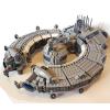
Here is my XL turntable, which has 11 dead-end stall tracks and one outlet track. (though it can be reconfigured to be as many or as few tracks as needed). It is spread out over a 64 x 64 XL make-shift base plate size made up of of 4 regular (32 x 32) curved road plates with quite a bit of overhang due to the outlet tracks and tower. The re-purposed signal tower is now being used to control the turn table. This control building is modular, and has a roof and second floor that come off to reveal inside details. The studs on the sides of the building are supposed to spell out the the yard's name, but I haven't decided on a good name yet. If you have any suggestions for a name with 10 letters or less, please post a comment with it below! This table can handle a 4-track long engine (around 64 studs) with a bit of overhang at the ends, such as with my Frisco 1522 4-8-2 steam locomotive as seen above. Diesel A + B unit sets would have to be separated and moved independently, but that's okay and actually accurate for some real world locations / railroads. The basic workhorse of the turntable is this four track long framework you see here. The table's modular control tower features a lower floor that's empty except for the staircase. The upper floor features a machine to control the turn table, a wall clock, and a old-fashioned rotary telephone. The table easily glides on an raised outer ring of tiles, and turns on a central 2 x 2 pivot point. This whole thing can be mechanized, much more easily than a transfer table, but it still needs fine tuning to make it work right. The outer ring of tracks is only attached to the base plates at two certain points: every other spot is held on by gravity. (plates on tiles) This is basically a very much enlarged version of this model here. I was working on a seven-stall shed in the same style as the tower to connect to the turntable, but the angles and hinge bricks weren't working out due in LDD. I guess it will have to wait until the turn table is built in real life.... if it is ever built in the real world. Comments, questions, suggestions, and complaints are always welcome, as usual and thanks for stopping by! -
Now that my semester is mostly over, I've been thinking about some of the projects I had to put on hold to focus on my senior design project this year - specifically, the PCB I developed a couple years ago to run two three-color track signals off a centralized microcontroller: The original design called for a three-color signal: red, yellow, and green. My plan was to divide my layout into blocks, with a signal placed on each block. I wanted my signals to respond in the following manner: - If a train is detected in a block, that block's signal must be red (block is occupied). - The signals in the blocks adjacent to occupied blocks must be yellow (block ahead is occupied). - Otherwise, the block signal will be green (block is unoccupied). This would result in the signals 'following' the train around the layout, such that any trains travelling on the same track would be aware of each other, hopefully avoiding collisions. In practice, I won't be running trains on the same track, but it's still a fun effect to have! My resulting truth table then looks like the following. Inputs A and S are the signals from the adjacent blocks and block sensor, respectively, while outputs R, Y, and G are the red, yellow, and green signals, respectively. It doesn't matter which 'side' I get a signal from an adjacent block, as either way I want the signal to turn yellow. In addition, if the block sensor sees a train, I don't care what the adjacent blocks are doing - the signal must turn red. After working through this table, it occurred to me that there were two ways I could build this signal controller... Form 1: NAND Logic This truth table is simple enough that I should be able to build it with basic logic gate ICs - and if I can do that, then I can do it purely with NAND logic gates, saving cost as I only need one type of chip to make this work. However, I still need to work on converting the truth table to a set of Boolean expressions, and from there into pure NAND logic. After doing a bit of research, it looks like I'll need multiple NAND chips, as most chips I find have only four gates inside them. However, I am space and cost limited, as I can only use four NAND chips (16 NAND gates) if I want to be comparable to the cost of the ATTiny85 at 36 cents per chip. Form 2: ATTiny85 Since I only have five inputs/outputs, the ATTiny85 microcontroller is perfect for this application - there are exactly five pins left over after accounting for power, ground, and reset. However, I would need to program each microcontroller, and doing so with a surface-mount device becomes problematic. The cost is also an issue, as each one costs about $1.16-1.25. Buying in relatively small quantities, I think I can get the cost of components for each board to about $5 per board - including connectors and such. The main issue with using NAND gate chips is the amount I'll need, and thus the space they'll take up on a size-limited board. I also will need some transistors to drive the LEDs as the logic chips can't drive that much current directly. The issue with using an ATTiny85 chip for each board is how to program the much smaller surface-mount versions, as well as the relatively large fixed cost of each chip - I can't work on optimizing out some of the cost in the same way I could with the NAND version. I want to use JST connectors for running cables between the boards and sensors and such, as they're directional and I don't have to worry about plugging things in backwards this way. There is another question I have for you all: what's the most useful form factor? My original project had a board that was designed to fit in a 4x4 stud area, but for this I'm leaning more towards a 2x6 or 2x8 board, as I think I can fit that into more spaces.
-

Mindstorms EV3 Lamp (Now with program explanation)
Eddie_Young posted a topic in LEGO Technic, Mindstorms, Model Team and Scale Modeling
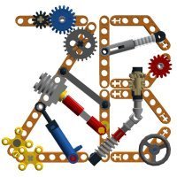
You know when you build a huge MOC and your lamplight doesn't illuminate the whole thing and you have to constantly aim and re-aim the lamp? You might not know it but this adds no less than 42 minutes to your overall build time! Outrageous! Luckily, I've found the solution: The video may be left to speak for itself: Now the build is pretty simple. The base was the toughest part. Getting two independant spinning axles througha turntable while keeping the area nice and clean! The whole structure rests on four tyres to eliminate vibration and the resulting sound. the bulb is clamped by a worm and 8-tooth gear. I did not alter any bricks to fit the bulb and the bulb can be taken out at any time if anyone requires a purely LEGO lamp. And who would dare! The lampshade is how it is because the lighbulb was very mean and melted through the system bricks that formed the first prototype. It brought a respectable amount of tears to my eye. This new framy lampshade has endured over two hours of maths homework with no sign of wear! Now, the programming did require some little thought. The aim in the vertical plane is done through a load of trigonometry, while the horizontal aim works directly with the IR sensor's "beacon heading" output. One thought I'm particularly proud of is my use of squared and cubed values to slow the motor down as they approach their desired positions, thereby eliminating any shaking from hesitation or even indicision! That's all I have to say but I'll be more than happy to answer any question from a fellow moving-LEGO-lamp enthusiast, if there ever was such a thing! Please check out my Wind-up Robot on LEGO IDEAS! Thank you, for reading my words! -
Hi all, In January 2014 I build a small 9v LEGO train layout. I use Mindstorms nxt 2.0 to control the trains and switches. Now I’ve found this video, I’ve uploaded to my YouTube Channel. The layout works like this: 1. Both trains are running on the outer track. The nxt motor controls the big yellow button on the Speed Regulator. 2. Due to small differences in the train motor and the weight of the trains, the come closer to each other. 3. If the distance between the two trains is to small (less than 3 seconds, seen by the ultrasonic sensor), the last train drives to the inner track and stops over there for 10 seconds. A nxt motor switches the switch. 4. The train on the outer track keeps driving. 5. After 10 seconds the train on the inner track moves to the color sensor, just before the switch and stops. 6. If the train on the outer track passes the other switch (ultrasonic switch), the train on the inner track starts moving to the outer track. 7. Then it all starts over again. Let me know what you think about this layout! I’m also curious how you guys control your trains and switches. Any automation with Mindstorms?? ?
-

What's The EV3 Motor Power in IR Control Mode?
StudRobotics posted a topic in LEGO Technic, Mindstorms, Model Team and Scale Modeling
Not really, but I found out that the motors in my GX EV3 peform better in IR Control mode than how they do in my program, and I believe that it is because the motor power is different. Each block in the EV3 programming software that moves the motors has a digit for how much power each motor should have. I'm wondering what this digit is in IR Control mode, because the motors act much better in this mode than how the do in the program. If anyone here knows the power of the motors when the EV3 brick is in this mode, please reply as soon as possible. It would be very appreciated. -
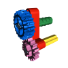
I was thinking about what I could do with the newly acquired bucket wheel excavator parts. Something that I couldn't build without these big yellow circles. That's how this strange idea came to be. The arms are motorized: they grab or drill and retract into the wheels. The compact and functional hand is my favourite part of the robot The two-wheel design makes it wobble a lot. Someone on youtube commented that it's headbanging to the music - genius!!! I might try making one with adjustable wheel angles next! Any suggestions? Check it out on LEGO Ideas!!!
-
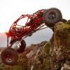
Already two years ago, I got inspired at defeating steep hills with the LiteJeep. That could already beat 50 degrees, but because of its high riding height (good for offroading) and relatively heavy PF L motors, I reckoned there would be more irons to put into the hill-climbing fire. Very important things for hillclimbing are sufficient grip, huge power and a low weight. Weight ultimately gives more grip, but it also causes the vehicle to flip earlier when it is located above the center of gravity. With these factors into the equation, I decided to create a vehicle with loads of grip, so with 4 rubber tracks, and with articulated steering to make a sturdy connection between right and left possible, which is essential for climbing: when any vehicle is climbing, the suspension does unexpected things, so a stiff frame and suspension setup are required. Lightweight design requires a low complexity too, so that is why articulated steering is chosen. Having a front and rear part to let the vehicle adjust its shape to the terrain is an option I used several times in my rubber-tracked vehicles. This is the first vehicle in which I used the maximum footprint instead of the triangular form, again for maximum grip. Please note that, when you choose for the sturdyness and simplicity of articulated steering ánd want to let it adjust to the terrain, the middle joint becomes very complex as it contains joints in two axes! There is always a place where pain comes back. The Law of Conservation of Pain holds here.. In this case, all the trouble was in the difficult joint, which took about 5 hours alone. Then for the power: initially an XL motor was used in the front, but having a driveshaft through the already complex dual joint proved to be impossible. And then the idea came. Why not generate the power at the place where it is needed? Why not, if there are two separate parts, have some powerplant in both front and rear? But then there was a problem: I have a very large project in which all my three L motors are used. This pushed me in the direction of using M-motors, which proved out to be a very good forced choice. Combined with the lightness of the overall model, they proved to have ample torque left with a 3:1 gear ratio, having enough torque to keep the four tracks spinning all time when grip was lost. This is amazing, and you can see why Lego has put two M motors in their latest Tracked Racer. But the limits of that thing are way lower than the Quattrack's limit. Using two PF medium motors for drive and one for steering, this one of my very few (and maybe the last) Lego Technic MOC with only 2006 components. The Sbrick will throw all range headaches away and have much less delay than the stone-age PF IR remote it is replacing. Why did I use such standard power functions components? The new PF servo is slow and quirky, a medium motor allows for much more smoothness in steering. Moreover, if you are driving at steep slopes like this, it asks all your concentration to keep it on the move. If you cannot feel where the remote control knobs are (The intrinsic problem of the Sbrick) the vehicle will fall of before you've compensated. So the old system proved to be the best system in this situation. The articulated joint actually contains 3 joints, to have a suspension force on it in both directions: up and down. That is why there are rubber bands and one shock absorber. By the way, also the steering joint is included. Now, because the front and rear part of the Quattrack are relatively conventional (no steering nor differentials), all the pain of good and accurate steering is shifted to the design of this central joint. I dare to state that the success of this vehicle relies for a big part on this 2D joint. In the video, the operation is explained. On this photo, it looks as if the ground clearance is half a stud. This is not the case; in fact, it is over 1 stud. The underside is very smooth, which helps the low superstructure to glide over obstacles. Because of the weight saving, I designed it to have very clean looks. Styling means more weight. However, I managed to squeeze in some little details like fake cabin flashing lights, front lights, rear lights, cabin seats and a steering wheel. The reason why I did this, is that I wanted it to be a possible real-life vehicle as well, not just a scientific experiment. Adding weight is bad for climbing ability, so I tested the Quattrack also with the cabin removed and say what !!? The climbing angle was the same. This front look shows all that. The Quattrack contains everything, but nothing more. You do not need a zillion pieces of Lego to break records. Only 556 grams of it is sufficient in some cases. The video is the proof of all my theories... [media] I have not put all text and photo's on Eurobricks. More is to be found on Brickshelf and MocPages. If you like my video's, you might want to take a look on my YouTube channel.
-
Help With EV3 Remote Control Program
StudRobotics posted a topic in LEGO Technic, Mindstorms, Model Team and Scale Modeling
I'm programming my EV3 vehicle to be operated by an IR beacon remote. I've successfully got the car to be able to move, but I'm stuck on something else. My vehicle has a 4-speed transmission, and a medium motor shifts the gears. I used the remote's topmost button (the one that turns on the green light on the remote) for shifting the gearbox. But when I press it, something goes off. It's really hard to say, but what I know is that the topmost button isn't acting like a normal button. So the motor keeps on moving until the IR sensor realizes the green light is off. I really need help with the program because I just want the topmost button to act like a normal button so I can press it to make the medium motor shift one gear with a one second wait before shifting to the next one. I would love a very helpful response from someone that knows how to program the IR remote and if there is no way to get the topmost button to get the result I want, an alternative would be nice so I can be able to shift gears with the push of a button on the remote. -

ROBOT WARS: Pulsar vs Carbide
PKW posted a topic in LEGO Technic, Mindstorms, Model Team and Scale Modeling
hi all, some months ago i made this video of lego battlebots, and now i'm posting it there because maybe you could be interested also for TC11, you'll find all the bot info in the video but i'll clone them here too, hope to bring up a brickshelf folder asap for the two bots (but i have to rebuild them due to pieces and electronics being used for witch doctor replica, cardiac two, fanmade design, killerhurts and recyclopse chassis, and other 3 500g class bot an grabber a lifer and a flipper) PULSAR weight: 700g size: 23x27x9studs weapon: 73g spinning drum with two single teeth 1900rpm strenghts: really effective wedge shape used to go under the opponent and lift them with the drum energy weaknesses: the drum isn't enough fast to launch the oppnent on the air, wheelholders may break off easily, weak wepon belt CARBIDE weight: 730g size: 32x32x9 studs weapon: 84g spinning bar 750rpm strenghts: great power and though armor, effective rear wedge weaknesses: the armor can e warped or bent and increase friction in the drivetrain, hard to control, high battery consumption here a photos from Ellis (pulsar builder) about size comparison here the video: NB it is really long, if you want, after presentation, you can skip to 11:02 to skip the fist fight (a bit long and boring) and save time without losing the most of the action! i'm keeping editing this with photos and videos from my twitter, it is hard to find them back but i'll try: CARBIDE PULSAR -
Hi guys I just finished my newest project: 2 AT-TE MOCs and want to show you all AT-TE Info Sheet by sunnyxi, on Flickr AT-TE 33 by sunnyxi, on Flickr I started building blue one in summer and finished the red one just a month ago. The blue one is just a simple MOC but the red one is much more complicated as it is motorized and can transform into a landing platform. AT-TE 19 by sunnyxi, on Flickr AT-TE 14 by sunnyxi, on Flickr It also has flood lights for night combat. AT-TE 1 by sunnyxi, on Flickr AT-TE 6 by sunnyxi, on Flickr The blue one has more space to carry troops and kyber crystals. AT-TE 27 by sunnyxi, on Flickr AT-TE 35 by sunnyxi, on Flickr AT-TE 5 by sunnyxi, on Flickr Thanks for viewing at my newest creations and make sure you watch the video! Comment and criticisms are welcome :D Full album and more pictures: https://www.flickr.com/photos/63137442@N05/albums/72157680455243206
-
Lego Trump is back, bigger, better and president of USA. Let's build big Mexico Wall. https://www.youtube.com/watch?v=fcgaQVOlMbw
-
[MOC] Waving goodbye to 2016 with this little RWD drift car!
896gerard posted a topic in LEGO Technic, Mindstorms, Model Team and Scale Modeling
As a last goodbye to 2016, I present this small red car. It is not really built to be particularly good looking (I used a wire bodywork to have a low weight) or to have a particular high speed. But what it does, is put a smile on your face. Technics are kept simple, there's an RC buggy motor next to a PF lipo batterybox in the middle, a PF medium steering motor before the front axle and an IR V2 receiver to enable 1 metre of infrared range when going outside. Please Lego... Please... do something about it. The frustration and anger about this appalling range is powering companies like S-brick. And that's why my future cars are having an S-brick, leaving this model as one of my last PF IR remote controlleds MOCs... We're making a fun car, right? So there is a silly spoiler and huge rear tires. By the way, these wide tires provide excellent traction in dry conditions, which is important for low-weight cars like this. The interior had to be sacrificed to have a low position for the drive motor and battery box. Because of this measure, the handling was quite good, but made much worse by the slow PF IR remote. In the end, of course there is the video: The longer story can be read on MOCpages and better photos are on Brickshelf. Have a nice 2017! -

Gauging Interest: Control Board for Two Three-Aspect Signals
Phoxtane posted a topic in LEGO Train Tech
As part of my quest to control my Lego train layout with an FPGA controller, I decided that I would want some railway signals that would change as the train passed by. I then realized how much of a mess that would be with wires running to and from each LED in the signal and the control board, so I thought to myself: "I wonder if there's something I can build that will help with this problem?" I'm curious to see if there's enough interest in this gadget for me to be able to make and sell them, so that's the main point of this post. Here's the result: EDIT 8-2-2016: Board version 2.1 images In addition, here's a video of one of the first versions of the circuit, before I had even started on designing a PCB. This demonstrates the basic functionality of the controller with a single three-aspect 'signal'. Description: This board can drive up to two three-aspect (light) LED train signals with as few as two I/O pins on the chosen microcontroller. It can be run off of either 3.3V or 5V supplies* a 5V, and will interface with logic signals of the same voltage. If you'd like to drive the two signals independently, it will take four I/O pins. Dimensions: 4 studs by 4 studs, not including the male header pins. As I have yet to receive the prototype for this board, I don't know if the mounting holes fit a typical Lego stud, or if they line up with the corner studs on a 4x4 space - however, I should be able to adjust this without too many problems. The header pins are the standard 2.54 mm/.1 inch pitch popularized by Arduino microcontrollers. Technical Specifications: Supply voltage should either be 3.3V or 5V* be 5V. Absolute maximum current draw should be ~85-90mA, typically ~41mA**. Operation: The IC used to make this board work is the SN74HC139DR, a two-line to four-line decoder. There are two decoder units in each chip, and as a result this board will happily drive two signals at a time, either independently or synchronized together. The A0 and B0 connectors are the least significant bit of the two-bit signal, with A1 and B1 being the most significant bit. There is also an active-low 'Enable' pin for each decoder, which is not broken out to a header; it is permanently tied to ground so that the board is always ready to change the signal. If the value sent to Signal A is 00 (A1=0 and A0=0), all of the LEDs in the signal remain off. If the value sent to Signal A is 01 (A1=0 and A0=1), the green LED will turn on and remain on as long as the 01 signal is applied. If the value sent to Signal A is 10 (A1=1 and A0=0), the yellow LED will turn on (and remain on as above). If the value sent to Signal A is 11 (A1=1 and A0=1), the red LED will turn on (and remain on as above). Signal B works in the same manner. If you want to set both signals to the same light, simply tie A0 and B0 together, as well as A1 and B1 together. If you want to drive the signals independently, don't do that Cost: My calculations for the cost of the components, the PCB, and the time it takes for me to assemble and test each board tells me I should be selling these for $21.99 (USD) apiece. If I was to have these mass-produced, it'd likely be cheaper - however, I'd have to be buying them in quantities of 100, or 1000, and there's no guarantee I could sell them all. As such, I would prefer to take orders from anyone who's interested in buying these and essentially produce them on-demand so I don't have to keep inventory around. Sales Pitch: You should buy this device because it reduces the amount of I/O pins required to drive two three-aspect signals by 33% (four pins instead of six for independent operation) or even 66% (two pins instead of six for synchronized operation). This reduces the amount of programming work that has to be done by the user. In addition, the board is thin enough that it can fit in a single brick's height; as such, it can easily be hidden under some landscaping or even placed under the ballast for a section of track! Moreover, it comes in a lovely purple color with a gold plated finish, thanks to the company who I get my PCBs from. <~~~~~~~~~> *The only change that this would require would be different values for the resistors; I currently have resistors on hand for a 3.3V version, as that is what my FPGA operates at. Typically, Arduinos operate at 5V, so I could potentially offer either variant to suit your needs 5V supply only! More will burn out LEDs and resistors, less will cause undervoltage problems. **The LEDs I prototyped with (and will use on my layout) have a maximum current draw of 20mA apiece, with the IC drawing ~1uA. If there's a problem with floating inputs, it is possible for two LEDs on each signal to be lit at a time, resulting in double the current draw. I have yet to see all three LEDs on at the same time! Now, having read all of this above: Would you buy this gadget? If so, how many do you think would buy, and how much would you be willing to pay for each one? As sad as it is to admit, I'm not able to compete on cost with cheap PCB assemblers in China. Another question: Would you want mounting holes on the board, similar to what I've show here? If so, would you want them to fit a Lego stud? Finally, just to make this clear: I'm not ready to sell these yet. I still have to receive and assemble my prototype, which isn't even the board pictured above (it is functionally identical, just without the helpful pin labels and slightly cheaper because it's a tad smaller). I'd be thrilled to be able to sell these to people once I've verified that it works and doesn't explode, however! -
[MOC] RC Camper Van with SBrick - 4 Studs Wide
SevenStuds posted a topic in LEGO Technic, Mindstorms, Model Team and Scale Modeling
So this was a quick, fun project. I gave myself the weekend to build the smallest RC car I could. My goal was 4 studs. This seemed reasonable since a battery box and SBrick are both 4 studs wide. With the width set in place, I quickly realized that making two connected parts would be the way to go so the model naturally became a camper van/RV with a trailer. The main car holds 2 micromotors and the trailer has 1 old-style battery box with the SBrick directly on top. More photo's here. Assembly photos are here. PS: I must also thank Mbmc as some of his micro RC MOCs were a good inspiration for this project.