Search the Community
Showing results for tags 'switch'.
Found 30 results
-
This is my LEGO model of the Excess Express from the Nintendo GameCube/Switch game Paper Mario: The Thousand Year Door. This is a project I started over a decade ago of the interesting train from one of my top favorite games of all time. It has gone through many iterations over the years, and figured with the remake on the Switch releasing soon, now would be the time to finally share it. As such this is based off the original GameCube version using the in-game 3D models for reference. The train consists of an engine with five cars. The entire model is 48" in length, uses over 3600 pieces, fully compatible with Lego train track, and electrified via the Powered Up! system. The retro-deco styled engine with it's wacky large central wheels. The brick-built center wheel is driven via a geared system from the front wheels, and the rear wheels are Big Ben Bricks XXL flanged drivers. The engine itself is unpowered and is pushed via the motored car. It is able to navigate Lego's tight track curves but with a lot of overhang. Custom elements include painted starfish and a few stripes on the front nose and windshield. The first two cars contain the Powered Up! system. The front two axles of the burgundy car are driven by a PU Large motor and the car is filled with pennies to make it heavier for better traction. The teal car contains the battery box/receiver and has an easily removable roof to access it. The other three cars of the train are mostly hollow aside from internal structure support. All cars have custom stickers for the starred car number on the roof. This project has been a labor of love for many years, and am glad I can finally share it with others.
-
Hi community, The BrickTracks R104 switches are already a while available on the market and the FX switches will follow soon. I ordered some FX switches, (I have only 9V track) and was wondering if someone already automated his switches using any kind of automation, using servos or anything else. I am completely aware that the driving mechanism of the BrickTracks switches are different than the FX switches (Rotate versus slide motion), so any idea is welcome. My switches will be placed on MILS modules, so there is some space to use a servo, just not knowing how to do so. The experience I have with the servo's on my level crossing controlled by an Arduino UNO are a bit strange. When the controller gets initialized, the servo's are 'flying' full in one direction (using the servo library), and If not proper controlled I guess that the driving mechanism of the switch will be destroyed if this happen. Knowing this behaviour, I guess also that it is recommended to set the switches in a kind of 'start' position before the servos are initialized, this should be executed before the end of an event. Anyone out there who have more experience with servo's and their behaviour who are willing to share it here? The do's and dont's, the pitfalls, ... Thanks in advance. Ludo
-

1930's modular railroad interlocking tower MOC - real world MOC (finished 2/13/23)
Murdoch17 posted a topic in LEGO Train Tech
I was inspired to build this industrial-looking old fashioned interlocking Tower by set number 60009 (Helicopter Arrest) and a number of old towers in my hometown of St. Louis, Missouri. In addition, the unusually-placed signal arm attached to the building is inspired by an mid-1960s WWII-set black and white film, (The Train) in which a French signal tower very similar to this one is used for some sabotage of a German train and is subsequently blown up in an Allied air raid... and yes, they really did blow it up - no miniatures were involved! Here you can see the chimney flue on the rear of the building. There is an abandoned OCTAN tank car also visible nearby. Upstairs is a heating stove for those cold winter nights, six lever frames for moving switches and a signal board for showing which route is currently aligned. The bottom floor features a (empty) gas tank, a chest for emergency flares and torpedo's, a trash can, plus a telephone. "This is getting out of hand... now there are two of them!" The one on the right is my original switch tower, while the one on the left is my Dad's (slightly different) copy. He paid for the model and I built it. I ordered the parts last Sunday (Feb. 12th), the three orders arrived Wednesday and Thursday and construction on the copy was completed last night. (the 16th) Thoughts anybody? EDIT: 2/13/23: Real world photos added! -

[MOD] Lego 60236 switch motorized with a power functions motor
brick-builds posted a topic in LEGO Train Tech
Hello, we made a mod for a 60236 to get it motorized and remote controlled. There are earlier solutions form other people available, so please see also the posting below. The mechanism is under the track and it's possible to put the motor a little bit outside, so it could be hidden in a small house. -
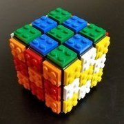
I have built a scale model of the Nintendo Switch video game console, featuring controllers that are detachable in a realistic manner, and the ability for the screen to be built in either direction. I have shown it at my local LEGO convention before, but have more recently built the red controllers and alternate tile screen option. Above is a version of the screen built with studs toward the top of the Switch, depicting Link climbing a mountain against a backdrop of a sunset over Hyrule, from The Legend of Zelda: Breath of the Wild. Below is a version of the screen built with studs toward the face of the Switch, but using 1x1 tiles to maintain a smooth pixelated surface for the screen, depicting the Master Sword in its pedestal in the Lost Woods, also from The Legend of Zelda. The controller attachment uses a combination of parts 30586 (Plate 2 x 8 with Door Rail) and 60478 (Plate 1 x 2 with Handle on End), which allows the controllers to slide unidirectionally in a method that I have not seen used in a set, though I have not verified that it has never been done before. Instead of the typical use as a hinge, I have used parts 3937 and 3938 for providing a slight indent to accommodate the rail, without the loss of structural stability that would occur from just having a gap or using a 1x2 panel. I have not yet built a controller grip for the "Joy-Con" controllers to attach to when separated from the screen, but the sliding mechanism is compact enough to not pose a problem. I have only built the controllers out of red and dark bluish gray / medium stone due to limited availability of the curved parts 30357, 30565, and 85080 (or 3063). To facilitate the screen being built at a consistent depth in either direction I have used 2x2 jumper plates, since the hollow studs provide a half-plate depth against the face of a plate or brick, but get covered by the tubes of 2x plates beneath the tiles. The console (excluding screen) contains 94 or 96 parts, depending on which screen style is attached. Each "Joy-Con" controller contains 47 parts, thus 94 parts for one pair of controllers. The screen with studs toward the top of the Switch contains 203 parts as shown, but is quite variable upon the design. The tile screen contains 180 tiles supported by 10 plates. Below are the separated sections of the build, for which the total part count of what is shown comes to 679 (92+2+4+94+94+203+180+10). I have submitted the idea on the LEGO Ideas website, and if anyone is inclined to support the product idea, that would be appreciated. If anyone has questions or feedback, feel free to comment below.
-
I finally have good pictures of the demonstrator model for my take on a cheap no-modification-required switch track motor. Have a look! The key that makes this work is that the servo acts on a slider, which pushes on the little spring-loaded switch point piece, rather than forcing the lever mechanism back and forth. As such, it takes very little force to change the switch from open to closed and vice versa. I'm using two of the 1x1x1 corner panels to trap the servo horn so that it pushes the slider back and forth, while a 2x2 corner tile pushes the point piece backwards and forwards. The actual switch lever needs to be in the 'open' position to allow the point piece to move back and forth properly; otherwise, the switch will stay closed even when the servo releases the point piece. I'm using an Arduino Uno, but you could use any Arduino or compatible clone as long as you get the pins hooked up right. It's a lucky coincidence that the servo is the size it is; two of the 1x2x3 panels form a nice enclosure that keeps it from moving about too much. It's important to get the older style that don't have the reinforcing ridges on the edges, as otherwise it won't fit. I used a small piece of paper folded on itself a couple of times to keep the servo wedged in tightly. I imagine you could use some of those 1x2 bricks with the vertical groove in them to help hide the servo cabling, but I didn't bother since this is only a demonstrator. Here's a better view of the setup without the track in the way. My servos came with a pack of three differently-shaped horns to put on them - I'm using the shortest one available to me (mine was 19.5mm long with six small holes in it and was the only one with one 'arm' on it). I also have not permanently attached it with the screws that also came in the package, mainly for the purposes of testing. Lastly, here's a picture of the support structure I built up to keep everything in place. I also made an LDD file of the structure as well as the slider mechanism and servo holder so that you can build your own! http://bricksafe.com/files/Phoxtane/digital-model-files/servoswitchtrack.lxf The hard part of this built is not the mechanism, but setting up the servo as well as the Arduino controller. If anyone is interested, I can do a more in-depth post on how these servos work and how to use them, but the basics go something like this: Attach the servo to the Arduino using the diagram on this page: https://www.arduino.cc/en/Tutorial/Sweep Test your servo to make sure it's working using the example code on that page (the servo should slowly move back and forth between its endpoints) Center the servo at 90 degrees - http://www.allbot.eu/build/allbot-arduino/centering-a-servo/ - this puts the servo at a known position for use in our mechanism Place the small one-arm servo horn onto the servo spline so that it's pointing across the servo body, not away from it. This allows the servo to reach the little pocket we've built and actuate the slider. This is the tricky part; you have to play around with the Arduino code to calibrate your servo for its switch track. These servos are mass-produced as cheaply as possible, so the actual physical position of the horn at the 0 and 180 degree endpoints will vary somewhat from unit to unit. For my servo, the two positions the servo should move to for a closed and an open switch are about 83 degrees and 113 degrees, respectively. The corner tile should barely touch the point piece when open, and should keep the point piece tight against the outside track piece without the servo struggling or forcing itself out of position. I made some minor improvements to this code for my demonstrator - the servo doesn't sweep between positions, but jumps between them, so it's faster to actuate. I also have the Arduino disconnecting the servo in between movements so it doesn't 'hum' while waiting to move to the next position. General improvements to this model would include building the mechanism out of DBG and black for the servo holder, as well as tidying up the wiring to the servo. The servo horns stand out quite a bit color-wise, but since they're nylon, they could easily be dyed black to match the servo housing, and the silver-colored screws that come with the servo horns could be touched up with some paint or nail polish to turn them black as well. The only downside to this mechanism is that you can't run a train backwards through the straight part of the switch when it's closed, since the point piece can't move out of the way. Since this is already being controlled by a microcontroller, it wouldn't be difficult at all to add some sort of sensor that would open the switch when a train is approaching it from the wrong side. As for overall cost, beyond the price for the pieces needed to build this barebones mechanism (I had all of the pieces in my collection): I bought a ten-pack of these servos for $2 apiece, and if you don't already have one, a small Arduino starter kit can be found online for $25. The Arduino Uno has six analog pins, so it can potentially control up to six servos at once. If you're starting out from scratch, the total cost for six motorized switches would end up being around $37 - which is much cheaper than the ~$125 it would take to build this out of genuine Lego parts (one battery box, six M-motors, three IR receivers, three IR remotes), and it doesn't take any PF channels.
-
At Brickworld 2011 in Chicago, OnDrew J. Hartigan made an interesting presentation about various types of modifications of standard LEGO tracks and switches (9V and RC). The following picture shows a modified switch with the switch throw on the opposite side to provide clearance for 8-wide and Longer rail cars. Unfortunately - and unlike most of the other modifications presented - there are no details on how to proceed. (According to Hartigan, this modification takes only 20 minutes). Can somebody provide details on how to proceed with this particular modification? (Copyright OnDrew J. Hartigan 2008 - 2011)
-
I used to call these signal towers as a kid. You find them near railyards where operators can flip levers and change signals down the track for engineers to follow. With the very limited space I have on my Small Door Layout I needed something narrow and tall. Keeping this to just 8 studs wide allows me to slip it between any two parallel rails. I kept the detail to a minimum but the part count is still 950. Here's a link to a good article about one of these towers that was replicated. https://heritagerail.org/2015/08/monticello-replicates-an-interlocking-tower/ Here's a link to a good wiki page. https://en.m.wikipedia.org/wiki/Interlocking I'll upload the .XML file to my Bricksafe page soon. Hope you like!
-
We just released our new curved switches! They are very handy to build compact layouts as you can move your switches to the curved sections and thus use the full length of the straight sections for platforms, cargo terminals, etc. As shown above, they can be used to build curved single crossovers. You can see our curved switches in action in the video below: The curved switches are designed to be fully compatible with the LEGO® grid. They fit into standard R40 curves; the inner line requires 2 and the outer line requires 3 standard curves to complete a 90 degree turn. The curved switches split the main line into two separate lines that are separated by an 8 stud wide gap at the end of the turn. They are also fully anti-studded, just like all our other train tracks. Let me know if you have any questions, comments or suggestions!
-
 In this topic you can ask help if you don't find a piece in LDD. You can also ask here about any doubt regarding part IDs, duplicate parts and the use of a specific part present in LDD. Before asking, try the hints listed below. Ensure that the Extended Mode is active The extended mode allow access to all the bricks included in LDD in each colour. To activate Extended Mode go to: Menu -> View -> Theme -> Extended Mode . . . [Image] Use the Search Field The search field is the textfield above the Bricks Palette. . . . [Image] Enter there the ID of the brick you are looking for, or any plausible word that could identify the brick you are looking for. Note that the IDs and the descriptions in LDD are the official LEGO ones, and could differ from those you can find consulting other sources such as Bricklink, Peeron, etc... Check the work of other users As last resource, check the index of the Official LEGO Sets made in LDD topic looking for the sets that uses the part you need. If you find it you can select it and read its Design ID in the bottom bar, then easily find it using the LDD integrated search function. Other Useful Tools LDD Part Finder (beta) Could be you can find useful this little software developed by the user DrFalken. You can find more informations here. Bricklink and LDD Manager If you know a set that uses the brick you are looking for, you can: - Obtain the part ID from Bricklink - Use the "Brick Finder" function in LDD Manager to convert the Bricklink ID to the LEGO Element ID Otherwise you can use LDD manager function "Search for attributes". Old related topics: Where to find these pieces in LDD Finding a dinghy in LDD CMF Decorations in LDD 4.3.6, Series 1-9 ...
 -
Hello again, I am looking for instructions of 753, 754 and 755. Didn't find them online. Do you know from where I can download them or do you have them?
-
I have quite a few switches and have been interested in modifying some of them for a while now. I found a couple PowerPoint presentations from BrickWorld in years past discussing how to modify switches. The one thing they do not cover is moving the throw to the other side of the track. Now, I know there are switches from 4DBricks in just about every configuration including with the throw on the other side. But if I have an over-supply of switches, and have no need to purchase more, then modifying my existing stock makes more sense. Is there a write up on how to move the throw it is that really something I will have to figure out for myself?
-
Hi all, In January 2014 I build a small 9v LEGO train layout. I use Mindstorms nxt 2.0 to control the trains and switches. Now I’ve found this video, I’ve uploaded to my YouTube Channel. The layout works like this: 1. Both trains are running on the outer track. The nxt motor controls the big yellow button on the Speed Regulator. 2. Due to small differences in the train motor and the weight of the trains, the come closer to each other. 3. If the distance between the two trains is to small (less than 3 seconds, seen by the ultrasonic sensor), the last train drives to the inner track and stops over there for 10 seconds. A nxt motor switches the switch. 4. The train on the outer track keeps driving. 5. After 10 seconds the train on the inner track moves to the color sensor, just before the switch and stops. 6. If the train on the outer track passes the other switch (ultrasonic switch), the train on the inner track starts moving to the outer track. 7. Then it all starts over again. Let me know what you think about this layout! I’m also curious how you guys control your trains and switches. Any automation with Mindstorms?? ?
-
Hallo, here is just an idea of a pait of switches which are parallel an uses a 40 and a 56 radius. just let me know in the comments what you think of this idea.
-
To all LEGO train automation enthusiasts, This is a short clip of the final version of our LEGO compatible track switch motor. It has a digital servo embedded in a 3D printed housing. This is a 'plug & play' solution: the motor is strong enough that it doesn't require any modification of the switch (you don't need to open the switch and remove the notch to reduce the force needed to flip it). I also added a picture of the back side so you can see how it can fit onto a LEGO® switch. The housing is made in a custom dark bluish gray ABS filament that matches the LEGO® tracks. The motor has a 6 by 6 stud footprint and it's 2 bricks + 2 plates high. We'll be making controllers for these motors as well, so you can connect them to your PC. However, the motors are fully Arduino compatible, so you can integrate them in you own DIY control system. What do you think ? We're working on a full range of automation gadgets for LEGO trains. What other automation challenges would you like to see solved ?
-
This is an early prototype of a 12V style button to control our track switch motors. The button has all the hardware it needs to control the motors, it just needs a 5V power supply (from a brick we're still working on). It has 2 LEDs to indicate the state of the button (the LED on the left is not positioned properly in the prototype and doesn't show in the video). The LEDs are in a hollow stud so you can customize the color by adding a transparent brick. There are 4 studs in between the LEDs so you can add a tile with a label to mark the button so you know what it controls. There are power connectors on the side of the buttons, so if you connect them side by side they can power each other. We're planning on making similar button for the traffic lights, decouplers, etc. For those of you who prefer not to use a computer or want to build a control panel in bricks, is this an approach that would work for you ?
-
Dear Eurobrickers, With 4DBrix we have always tried to keep an open communication with the AFOL community. (Although I have to admit that for the last few months, due to our kickstarter campaign, I didn’t have enough time to do this as much as I would have liked). I really enjoy the conversions on this forum and appreciate your feedback and input which has had a significant impact on what we do. Unfortunately, I have to revise the ‘openness’ on that level. A few months ago we introduced the concept of ‘modular track switches’ we developed for LEGO PF train track. It was brought to my attention that our concept has already been copied… in a rather shameless way, they didn’t even bother the find another name and also use the term ‘modular’. Developing a concept like the ‘modular track switch’ system takes a significant amount of time and effort, however, copying the final concept only takes a fraction of that. We have no problem with fair competition but stealing ideas straight out of kickstarter/forums is a serious issue for innovation… We have been working on other concepts to extend the track selection for LEGO trains and would have liked to discus them with you. Unfortunately, we’re no longer able to do that unless we’re willing to risk that our ideas are being stolen before we can even release the product. We have to evaluate what the implications of this are long term. But for now, I truly regret we can no longer have these open, public discussions. You’re however very welcome to contact me directly at info@4dbrix.com. As usual, all your feedback is welcome...
-
[MOC][RC] motor-selector with additional gearbox/output-selector
TechnicSummse posted a topic in LEGO Technic, Mindstorms, Model Team and Scale Modeling
Since i cant testdrive my newest speedracer because of the rainy weather, i decided to clean up my "in progress moc corner" and found this: A as small as possible electric doubleswitch, wich you can use, to control 2 different motors with the same RC output. You can simply select wich one you wanna use. At the same time you can use it to control a gearbox, or output-selector, as you can see in the video. The idea to invent this, was, to realise as much functions as possible in a rc-model, with a limited amount of receivers (in my case just 1 RC-unit). You can use the auxilary output of the RC-unit to control the micromotor, and thus switch between 2 different functions ( for example drive and a pneumatic compressor). The output-selector can be used, to switch for example a servormotors output between steering and pneumatic-switch. "Why so complicated, you could just use the auxilary output for the compressor" -> well... you could do that and beeing limited to the auxilary current limits (~500mA). Also you wont have the gearbox/output-selector then ;) While using this, you can power your compressor (or what ever you want) with the "unlimited" power of the RC-units buggy-motor-output. AND fine-controll it with the 3-step forward, 3-step-reverse-control. It is also possible to control this with the RC-units steering output instead of the micromotor... like that you still have the auxillary-output free for use. How it works: The trick here, is to angle the 2 switches axles by 60 degres (45 would be perfect, but this is ok ;)). But you need to try the right 60 degres angle... only 1 position works, otherwhise you will have 1 motor switched on in one position, and 2 motors beeing on in the other position. The gearbox/ output-selector in the video can be simplified a lot, this is just to show, how it could work. I am pretty sure, there are some more things you could do with it... also with regular power functions ;) -
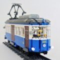
This was an experiment of automation of a tramway line with an old LEGO RCX brick: All sensors and cables are 100% LEGO. There are 8 light sensor, 4 (two couples, one couple for station and one for switch zone) on input 1 and 4 on input 2. 3 output, output A (station 1 - switch), output B (station 2 - switch) and output C (switch zone). Everything is handled by NQC program
-
We just added the new track segments needed to build rail yards to our Modular Track Switch system kickstarter campaign. There are 3 new 3D printed segments: rail yard diverging track (left or right turn): designed to put the tracks of the ladder at a distance of exactly 8 studs apart. rail yard adapter: designed to make sure all the track align nicely at the end or connecting the track of a bidirectional rail yard. bumper track: to have an elegant way to end the tracks of a one way rail yard. The system work for both one way and bidirectional rail yards: You can find all the info on our kickstarter campaign: https://www.kickstarter.com/projects/4dbrix/modular-switch-track-system-for-lego-trains
-
Anyone looking forward to getting their hands on the new Nintendo Switch? I'd say it's a very ingenious device with detachable controllers!
-

PF Polarity Switch Differences
BrickWild posted a topic in LEGO Technic, Mindstorms, Model Team and Scale Modeling
Brickshelf user "lukasz7792" has just posted an interesting comparison picture of an older & newer PF Polarity Switch. The one on the left has a black reversing switch and the one on the right does not. Does anyone know why it was omitted? -

[TC10] Pneumatic 'Nemesis'
Aris posted a topic in LEGO Technic, Mindstorms, Model Team and Scale Modeling
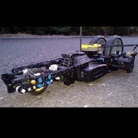
Dear all, For the pneumatic contest, I've built a huge robot called ''Nemesis''(from the ancient greek goddess) and I would like to share it with you. Nemesis has 22 pneumatic functions operated by a double compressor. All pneumatic valves are operated only manually according to the competition. Has a weight of 8kg and consists of 8000 lego technic bricks. Total air cylinders : 26 large 11 mini The compressor uses 2 large pneumatic pumps operated by a PF XL motor. The maximum pressure that can be reached by this pneumatic system is 28 psi with fresh batteries. Due to more than 30 pneumatic ''T-air pieces''pressure cannot reach a higher level because there is a huge drag and the XL motor has no power to rotate more. The length of pneumatic tubes are between 0.5 and 1.5 meters long. Due to the large hoses, large air storage is needed because there is a lot of air loss in the system. The air of the whole system is stored inside 2 lego air tanks (although the system needed far more) : The compressor has an auto-pneumatic switch using a large cylinder, which turns the air engine off when the pressure reaches 24 psi. A manometer is used for showing the air pressure at any time. Functions : Nemesis has 2 arms. The bigger front arm has 15 pneumatic functions and the small back arm has 5 pneumatic functions. The small back arm has the following movements : a) small gripper b) elbow1 c) elbow2 d) shoulder e) shoulder rotation The huge front arm has the following movements : a) large gripper, operating 10 fingers independently having 2 mini cylinders each b) wrist, operating 2 functions (up-down and turning) c) elbow d) shoulder e) shoulder turning Besides, the robot has 2 more pneumatic functions : 1) Face movement 2) A third gripper which is mostly for fun (e.g. for scaring house cats) Here is the video of the project : Thanks for watching Good luck to everyone! -
Hi all, I've been playing with some ideas for remotely switching my tracks. Here's a link to the 'proof of concept' mockup I've made of my progress to date. It's very much cobbled together, but I think it will work on my layout, to give me remote access to distant points. Its not a 'pure' lego solution, but it's unobtrusive and relatively cheap. This requires modification of: - The point (to remove the 'click' when the track gets switched - there's too much resistance for a small servo to overcome). - The lego 'cupboard' (to fit a small servo inside, and cut a hole in the door.) I tried modifying a small brick, but the servo was just a fraction too wide. The cupboard seems to work well. The only wiring visible in the final layout will be three very small wires running from the cupboard. I'll put together something more detailed once I have a version installed and running, if anyone is interested.
-
Hi all, Just made a LDD file of my design of a M-motor track switch. Some inspiration from around the net, but for people looking, here is a solution. LDD File. M Motor switch track design Switch track goes between the red tiles and the rest. This is for a left-side switch track, mirror for right side. Have fun.