Search the Community
Showing results for tags 'arduino'.
Found 29 results
-
(1).thumb.png.b4d6c907fe73903aec1adfd3cd481a19.png)
Lego quadruped Arduino? (glowy)
glowytheglowbug posted a topic in LEGO Technic, Mindstorms, Model Team and Scale Modeling
my first time using arduino and geekservo, not much experience in C but have experience with python I'm planning on making a 8dof rc walker with an arduino that can object detect with 2 ultrasonic sensors /distance sensors, 2 motors per leg hopefully can work made prototype out of only lego and coded with pybricks -
Lego 51515 Bluetooth Object Detection Robot
osullivp posted a topic in LEGO Technic, Mindstorms, Model Team and Scale Modeling
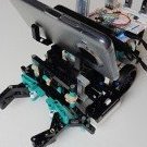
Hi all, I've been working on a Lego 51515 robot that uses computer vision to detect an object and then pick it up. Here is a video: The robot works as follows: 1) Objects are detected by a free TensorFlow Android App, available on Google Play (ArdObjectTracker) 2) The detection data is sent from the mobile via Bluetooth Classic and picked up on the Arduino board by an HC-05 module 3) The object detection data is then processed and converted to robot movement instructions which are then sent to the Lego hub via the BluetoothLE module (HM-10) 4) Finally, the Lego hub (running a Python program) receives the instructions via a BluetoothLE notification and then moves to pick up the object I have shared the code and more details on this Github page: https://github.com/osullivp/Lego51515BLEArduinoTensorFlow Hope you all find this helpful! Regards, Paul. -

New version 1.0.0 of Legoino Arduino library
Cornelius posted a topic in LEGO Technic, Mindstorms, Model Team and Scale Modeling
I am very happy about all the feedback and contributions which take the library to that step. Today version 1.0.0 of the legoino library is released! After over a year of learnings and feedback i have reworked the library to be more consistent and to make some things easier. Unfortunately this was not possible without breaking changes. This means some functions and methods has to be removed or renamed. To make the migration of your sketches easier, just have a look into the Migration guide provided on the github project page: Migration guide New features Duplo Train support Enriched Motor commands (maxPower, brakingStyle) Support of setAbsoluteMotorPosition, setAbsoluteMotorEncoderPosition Callbacks for changes on hub properties and sensor values PowerFunction (IR) functions included Hub Emulation (powered up to powerfunction translator) Adding of getHubName rework of log messages to the standard log_d, log_w, log_xx messages. Log levels could now be switched via the Arduino environment Contribution I am very happy about the whole community who participates in that library and contributes with ideas and your cool projects that uses the legoino library. If you have any questions, ideas or need help, you can just contact me. Looking forward to all the cool stuff you are building with the new version of the library. Cheers, Cornelius -
 Hello everyone: I am glad to share this project, the mining excavator, based on Cat 6090. Phisycal Configuration: The Lego Cat6090 is a motorized digger on tracked wheels, 2 XL motors provided enough torque. On the track frame is placed the main structure, and a heavy duty turntable allows good rotations, without fricctions. The turntable is rotated by means of 1 XL motor. The main structure contains: the XL motor for turntable, the air compressor, 4 servos for pneumatic valves and the controller. The design is ultra compact in order to meet the requierement of size/scale. The tracked whell is ultra rigid structure, designed to resist extreme load. The air compressor has 4 XL motor and 2 pneumatic pumps, in order to provide a constant air flow and high pressure, both pumps are de-phased 180° in order to reduce vibrations. 4 PF-servos open/close 2 way air valves, to command all pneumatic actuators. The boom has 2 large pneumatic actuator. Due to heavy height of the boom, 4 spring supply extra force during the elevation. 2 large pneumatics actuators push/pull the arm, those actuators are placed below the arm. 2 large penumatics actuators dedicate to rotate the bucket. 1 medium pneumatic actuator, open/close the bucket. Electrical configuration: Three 18650 batteries provide an average of 11.1 V, the compressor are suplied with 11.1 V, and the servos, lights and turntable motor are suplied with 9V. A BMS (Battery Managment System) manages the charge and the discharge durgin the operation. The tracked frame is steering by the use of 11.1 V, and as well is manage by the use of a BMS. On Board System (OBS): The name given to the controller. There are two systems, one for the main structure, and the secund is used to move the tracked well. The main controller, is a server TCP/IP protocol. The controller has a ESP8266 microcontroller with a TCP/IP stack, this controller is able to be programmed in arduino languaje (also micropython) - Teh ESP8266 is used as a sever, Motor driver: used to control the compressor The 4 PF servos are controlled by means of digital outputs, and the lights. ld293d, this is a H-bridge used to control the turntable motor. The second controller, is a ESP8266 as a client, and controls the speed of the tracks. Also, it has a BMS in order to regulates the charges/discharge of the batteries Accessories: 1) Josyticks: Two joysticks, with 4 dof (degrees of freedom) each of one plus a on/off button, are connected to the server module. 2) App: An application developmented under Android studio is used to visualizate the air pressure and electrical current, this app is WIP (work in progress). Conectivity: The comunication used is socket TCP/IP- Main features: maximun pressure reached: 52 psi (358 Kpa) Voltage bus: 11.1 V Compressor electrical consuption: 23 W Weight: 6 kg Length: 30 cm width: 20 cm height: 30 cm Here some pictures, during the construction and commissioning Note: my apologies for my primitive english
 -
Hello everybody, I'm starting this topic because I want to start automating my Lego Train layout. I am new to this so I have questions you might have the answer to and with that I hope this topic will help other newbies in the future. For starting off I'm thinking of buying: 1 arduino mega 2560. To control everything. 2 L298n modules to control 4 pf motors, for as many track switches. 6 (or more) lm393 lightsensetive optical sensors for train detection. 1 HC05 bluetooth module for communication with bluetooth devices. I think I am all set for hardware. Maybe a 12v powerline to power the L298n's. I have two powered up trains, which I hope to be able to control with the arduino too, didn't find anything about it yet (didn't look hard either though). Is this the right way to go Or do I miss something? Thank for you help.
-

Arduino -Many motor question
knotian posted a topic in LEGO Technic, Mindstorms, Model Team and Scale Modeling
My diorama is getting finished up. Now I use a mix of Ev3, a panel of Lego switches and Lego IR for control. Expanding EV# is $$$ out of question, Sbrick is not really an option since nothing freely travels. Looked at Arduino and the Motor Shield, One key question---how many motors can be controlled with one arduino and MULTIPLE shields? Is that even an option? I'd like to stay with PF Is there another micro that I should look AT? By the way I am now at 9 motors and am planning to go well past 20. -
This rail crossing is automated by two Arduino's. One Arduino will take care of the actual crossing (making the freight trains start/stop and the signals) the other Arduino controls the passenger trains which start/stop from two different stations. Because there's only one priority track for the passenger trains on the crossing, but both stations have two tracks, the latter Arduino also has to control the direction of the passenger trains on the crossing and also flip the switches to make sure the passenger train ends up at an empty track at the station. Both Arduino's have some low level communication between them: as soon as a passenger train is started, the crossing-Arduino is told to put the lights on red and to stop the track. The crossing-Arduino has a setting that tells it for how long the lights should be red. Oh, and there's of course also the Lego Terminator. Enjoy!
-

How could I provide power and/or data coupling between train cars?
TK2241 posted a topic in LEGO Train Tech
Hello all, I'm trying to find a way to create a power/data coupling between train cars that can be connected/disconnected like the car coupling magnets. Has anyone done anything like this? Background: This is so that I can supply power and control to LED lights (and maybe other devices) in the cars being pulled behind the engine, which will provide the power and control unit (Arduino based MCU) I've tried using a micro USB magnetic connector, but they are too bulky and don't flex easily enough for this. I'd love to find out if anyone has engineered anything similar. Thanks in advance! Arlo -
 This is a fully functional prototype of a brick (2 x 4 x 1) that we developed to make it easy to control PF motors with Arduino boards. It has a PF connector on the top to connect the PF motor and a 4PIn cable to connect to the Arduino board; it has 8 anti studs on the bottom to connect it to LEGO bricks. It allows controlling the direction and speed of the PF motors. We tested it with the M-motor, L-motor, XL motor and the train motor. This is the brick in action with an M-motor: Let us know what you think or what you would use it for!
 -
Hi, I'm new to this forum and what to share my project of the last months: Arduino Powered LEGO train! Check this video to get the first look: What i can do right now: Arduino MEGA powered trains Up to 3 trains (can be more, not tested yet) Self written C++ code for controlling the trains. Trains chooses random his path, no predefined paths yet. HTML5 Web Interface Canvas dynamic train layout Control trains and Points Check status of tracks and Points reset MEGA MEGA connected to Raspberry Pi with send/receive commands via SocketIO (temp solution, waiting for the Ethernet Shield!) Working crossover Working red/green signals (not on video) Magnets in Trains to let reed sensors detect the trains Differente speeds per tracks Multiple station segment (wait a couple of seconds on that segment) Cargo segment (wait couple of seconds and reverse) Track in video has 18 track segments, 4 normal points, 1 double point, 1 crossover, 1 red/green signal, 2 station segments, 1 cargo segment. Some issues left: Speed of the MEGA, not always fast enough to check reed sensors. USB connection to Raspberry Pi not as stable Lots of crashed :) longest stable run with 3 trains: 4 minutes... with 2 trains: 10 minutes Components used (most bought at BangGood) Arduino Mega with shield for connections modified points 3 HW-95 Motor drivers 1 powerfull IR led lots of wires (used old CAT5 wires!) LOTS of time... So far for today! post pictures of details later. Herwin
-
To all LEGO train automation enthusiasts, This is a short clip of the final version of our LEGO compatible track switch motor. It has a digital servo embedded in a 3D printed housing. This is a 'plug & play' solution: the motor is strong enough that it doesn't require any modification of the switch (you don't need to open the switch and remove the notch to reduce the force needed to flip it). I also added a picture of the back side so you can see how it can fit onto a LEGO® switch. The housing is made in a custom dark bluish gray ABS filament that matches the LEGO® tracks. The motor has a 6 by 6 stud footprint and it's 2 bricks + 2 plates high. We'll be making controllers for these motors as well, so you can connect them to your PC. However, the motors are fully Arduino compatible, so you can integrate them in you own DIY control system. What do you think ? We're working on a full range of automation gadgets for LEGO trains. What other automation challenges would you like to see solved ?
-
hi all, I have just started into the world of Lego trains and controlling them with Arduino and i'm afraid it's become somewhat of an obsession! I have always loved Lego and trains since I was a child but could never afford it. I have a son who's 6 and shares my love of trains so I figured now was a good time to start! :-D I have limited amount of Lego at the moment, and have been mucking around in LDD and Stud.io building some signals, etc..this also includes using Arduino to control lights as well as trains..my first try with using some IR transmitter LEDs worked, but not real well which made me wonder whether IR is really the best method of control..I have read alot of comments already from people that RF is really the way to go so I will try that next when the 433Mhz Tx and Rx pair arrive. This led me to think of the next weakest link in the chain..the battery, which only lasts so long and is a pain to have to pull out and change..I know Lego and even third party companies have a rechargeable battery, but I'm buggered if I'm gonna pay $100-120 for each one!!! I've never had any 9v or 12v rail-powered Lego, and the way I understand it, you switch on the control, it powers the rail so much and makes the train go...but what if the rail was powered on all the time and you still controlled the train with an internal controller (like the RF receiver). Any thoughts on this? Sorry if I sound like a noob, since I have no experience with how the track-powered system works. sPy from Oz.
-
Hey, A few years back I set up a layout which consisted of one big loop with a couple of side tracks where trains can be parked. So multiple trains were running on the same loop. This system had a central controller and the downside of this was that a lot of times the system had to wait for a train to come in or there were only two trains at the maximum running around. This time I've made a system with six side tracks and every side track has its own controller. So the choice wether to park a train on the side track or not is done locally based on a few variables like distance with the previous train and how long the side track was not occupied. A video says more than words so enjoy :)
-
Hi Guys, I got a bit carried away with my latest lighting setup and thought I would share my progress. I started off just wanting front and rear white/red lights but... well video's speak louder than words.. I have an ESP8266 onboard programmed with the Arduino IDE. The motor is controlled with a RC brushed motor ESC and the LED's (6 in total) are all programmable so they only need 1 output pin for all 6. It is communicating by MQTT and at the moment I am using Home Assistant just as a test controller but the plan is to use it with 4DBrix's nControl software as the features become available. A benefit of using Home Assistant lets me control it from my phone or PC. It will work across the web as well but I don't really have the need to control my trains from outside the house. Not yet anyway... I'll get some video's about the build up when I can Mike
-
Greetings. Thanks to herwin's Arduino trains and Lowa's nicely printed track switch motor, I feel Arduino inspired again. I remember I had bought some eBay SG90 servo motors and 3D printed a servo mount at my local public library last year. I dug them out and in 1 - 2 hrs I have it working. I was pleasantly surprised how easy it was to build and code. I reused my Arduino PF train module and code sketch. I connected the servo motor to +/- power and one of the PWM pins. Measured the angles needed for the servo arm to be at to flip the switch. Put the values in the servo.write() function and viola! The pinouts on this servo motor are brown wire is ground, red wire is +5V, and orange is control signal. It can be used with a push button switch to activate instead of fancy Bluetooth devices. That could be useful for public displays where the kids (or adults) can press buttons and watch the train as one half goes one way and the other half tries to go the other way.
-
Hey all, I'm working on a big automation project and I needed some automated rail crossings for that. This was already a project on itself which I like to share with you. I work with the 9V system and make trains stop by disabling isolated segments in the rails. That princicple is also used in the automated rail crossing. The crossing is controlled by a printed circuit board which I have designed myself. The PCB is multifunctional and can control two single crossings or one double crossing. This means that the board has two connections for sensors, two connections for signals and two connections for isolated track segments. Printed Circuit Board The heart of the system is stand alone Arduino chip. When the sensor is triggered by a train that is passing by, the non-priority track is disabled and the concerning signal is put to red. As long as the train triggers the sensor, the non-priority track remains disabled. When the train has cleared the sensor, a timer is started to make sure the train has left the crossing before the non-priority track is enabled again. This timer is adjustable by means of an adjustable resistor. Since the PCB can control two crossings, it contains also two adjustable resistors. The value of the delays is displayed on a 4-digit display. This way the system is flexible and can cope with slower or faster trains. Sensor Ofcourse you want to see the thing in action, so I also made a video. In this layout a double crossing is controlled by the PCB.
-
LEGO compatible bricks for Arduino
Lowa posted a topic in LEGO Technic, Mindstorms, Model Team and Scale Modeling
I'm working on a range of bricks for Arduino - mechanically compatible with LEGO technic, electronically compatible with Arduino - which I plan to make available in our bricklink store early next year. Below you have a short video with a demo: a servo motor controlled by a rotation sensor, both are connected to an Arduino nano board. What do you think ? What else would be useful? Both the motor and sensor are fully LEGO compatible: Some technical details on the motor and sensor: Motor: 0-180 digital servo housing dimensions: 3 x 4 x 5 studs technic axle connection to motor 4 technic peg connectors on the front 4 technic axle connectors on the sides (2 on each side) Sensor: measures rotation with a resolution up to 1 degree variable resistor 360 rotation capabilities housing dimensions: 3 x 4 x 2 studs technic axle connection to sensor 4 technic peg connectors on the top -

Gauging Interest: Control Board for Two Three-Aspect Signals
Phoxtane posted a topic in LEGO Train Tech
As part of my quest to control my Lego train layout with an FPGA controller, I decided that I would want some railway signals that would change as the train passed by. I then realized how much of a mess that would be with wires running to and from each LED in the signal and the control board, so I thought to myself: "I wonder if there's something I can build that will help with this problem?" I'm curious to see if there's enough interest in this gadget for me to be able to make and sell them, so that's the main point of this post. Here's the result: EDIT 8-2-2016: Board version 2.1 images In addition, here's a video of one of the first versions of the circuit, before I had even started on designing a PCB. This demonstrates the basic functionality of the controller with a single three-aspect 'signal'. Description: This board can drive up to two three-aspect (light) LED train signals with as few as two I/O pins on the chosen microcontroller. It can be run off of either 3.3V or 5V supplies* a 5V, and will interface with logic signals of the same voltage. If you'd like to drive the two signals independently, it will take four I/O pins. Dimensions: 4 studs by 4 studs, not including the male header pins. As I have yet to receive the prototype for this board, I don't know if the mounting holes fit a typical Lego stud, or if they line up with the corner studs on a 4x4 space - however, I should be able to adjust this without too many problems. The header pins are the standard 2.54 mm/.1 inch pitch popularized by Arduino microcontrollers. Technical Specifications: Supply voltage should either be 3.3V or 5V* be 5V. Absolute maximum current draw should be ~85-90mA, typically ~41mA**. Operation: The IC used to make this board work is the SN74HC139DR, a two-line to four-line decoder. There are two decoder units in each chip, and as a result this board will happily drive two signals at a time, either independently or synchronized together. The A0 and B0 connectors are the least significant bit of the two-bit signal, with A1 and B1 being the most significant bit. There is also an active-low 'Enable' pin for each decoder, which is not broken out to a header; it is permanently tied to ground so that the board is always ready to change the signal. If the value sent to Signal A is 00 (A1=0 and A0=0), all of the LEDs in the signal remain off. If the value sent to Signal A is 01 (A1=0 and A0=1), the green LED will turn on and remain on as long as the 01 signal is applied. If the value sent to Signal A is 10 (A1=1 and A0=0), the yellow LED will turn on (and remain on as above). If the value sent to Signal A is 11 (A1=1 and A0=1), the red LED will turn on (and remain on as above). Signal B works in the same manner. If you want to set both signals to the same light, simply tie A0 and B0 together, as well as A1 and B1 together. If you want to drive the signals independently, don't do that Cost: My calculations for the cost of the components, the PCB, and the time it takes for me to assemble and test each board tells me I should be selling these for $21.99 (USD) apiece. If I was to have these mass-produced, it'd likely be cheaper - however, I'd have to be buying them in quantities of 100, or 1000, and there's no guarantee I could sell them all. As such, I would prefer to take orders from anyone who's interested in buying these and essentially produce them on-demand so I don't have to keep inventory around. Sales Pitch: You should buy this device because it reduces the amount of I/O pins required to drive two three-aspect signals by 33% (four pins instead of six for independent operation) or even 66% (two pins instead of six for synchronized operation). This reduces the amount of programming work that has to be done by the user. In addition, the board is thin enough that it can fit in a single brick's height; as such, it can easily be hidden under some landscaping or even placed under the ballast for a section of track! Moreover, it comes in a lovely purple color with a gold plated finish, thanks to the company who I get my PCBs from. <~~~~~~~~~> *The only change that this would require would be different values for the resistors; I currently have resistors on hand for a 3.3V version, as that is what my FPGA operates at. Typically, Arduinos operate at 5V, so I could potentially offer either variant to suit your needs 5V supply only! More will burn out LEDs and resistors, less will cause undervoltage problems. **The LEDs I prototyped with (and will use on my layout) have a maximum current draw of 20mA apiece, with the IC drawing ~1uA. If there's a problem with floating inputs, it is possible for two LEDs on each signal to be lit at a time, resulting in double the current draw. I have yet to see all three LEDs on at the same time! Now, having read all of this above: Would you buy this gadget? If so, how many do you think would buy, and how much would you be willing to pay for each one? As sad as it is to admit, I'm not able to compete on cost with cheap PCB assemblers in China. Another question: Would you want mounting holes on the board, similar to what I've show here? If so, would you want them to fit a Lego stud? Finally, just to make this clear: I'm not ready to sell these yet. I still have to receive and assemble my prototype, which isn't even the board pictured above (it is functionally identical, just without the helpful pin labels and slightly cheaper because it's a tad smaller). I'd be thrilled to be able to sell these to people once I've verified that it works and doesn't explode, however! -
After a month, my Arduino clone has arrived from China. I plan to use it to add some inexpensive automation to our LUG's ad hoc layout. We are starting to display trains and don't have anything permanently built. Some of our events are outside in the park where there is no plug in power. One of the requirements would be battery power option. We are basically starting new with the current LEGO train and power offerings. We agreed to make Power Functions our club standard. I selected an Arduino clone. I figured for $4 USD, it is not a big lost if I fried it. There is a reason it is $4. The clone is not quite exactly the same as the real Arduino UNO. It uses a CH340 USB to serial chip instead of the FTDI USB to serial chip found on the real Arduino. In order for the Arduino IDE to communicate with the board, the CH341 driver has to be installed. It doesn't come with the IDE software from the Arduino website. The driver can be downloaded from the Chinese manufacturer's website. Note the site is in Chinese: http://www.wch.cn/do...341SER_EXE.html For a quick test, I hooked up an IR LED desoldered from an old DVD player remote to the board and wrote a simple sketch. I made use of a LEGO Power Function library (http://forum.arduino...p?topic=89310.0) Some resources on the Internet say IR LED in the 940nm range works best for Power Function IR receivers. It worked! And it was not as difficult as I thought it would be. I've never used an Arduino before. More eBay parts are to arrive from China. I'm planning to use reed switches for detection. I think they are the simplest to set up and tear down with just two wires to connect. I ordered inexpensive SG90 servo motors to control the switches. I still have to figure out how to mount them on other club members switch tracks and remove at the end of events. I think this is going to be fun.
-

I'm Tim, I'm new round here and I want to introduce you to bre
brebo posted a topic in Hello! My name is...
brebo Hi, I have launched a KickStarter (crowdfunding) campaign for a simple, low cost and intuitive system to invent and recycle electronics using Lego. Have a look [removed url] Let me know what you think. Thanks! -
I just saw this on kickstarter, quite nice idea :)
-
Some time ago a group I'm engaged in got some money to create projects for our city festival (sort of). For a bunch of reasons one of the main projects fell through and we needed a replacement. I suggested a display with Lego trains controlled by Arduino. Last week was presentation time. It's a first iteration so I wanted to make it simple yes a fit fun to look at. The trains go in opposite directions in an oval. There are two stations where the trains either wait five seconds or wait until the upcoming track part is clear. If the waiting time is up and there is no other train in the way it's go-time. Since the trains go in opposite directions, the switches can be static. You can check out a more in-depth description on my site: http://greytag.se/lt/showtime/ Let me know if you have any questions or comments.
-

Cheap Low Latency Power Functions Controller With Bluetooth
finhudson posted a topic in LEGO Technic, Mindstorms, Model Team and Scale Modeling
I've created an Arduino shield to control Lego Power Functions: An Arduino is a small, programmable microcontroller with lots of I/O (input/output) pins. It can be programmed from a computer, and it can interface with various devices. An Arduino shield is a circuit board that mounts onto the top of an Arduino to give it extra functionality. It is powered from a Power Functions plug, and has 3 channels that can be controlled via bluetooth, or programmed with the Arduino. See the kickstarter for more info: http://kck.st/1KqXFFV, and if you want one, please consider backing it. I will post some images of it in various models if you guys like it. What are your opinions on it, or do you have any improvements to suggest? -

Printing LEGO with a fully-functional 3D printer made of LEGO bricks
Gosse Adema posted a topic in LEGO Technic, Mindstorms, Model Team and Scale Modeling
Update september 2015: I have build a new extruder for this printer. It's now capable of printing chocolate. ------------------------------ Although it's not a 100% lego build. I think it's worth mentioning in this forum. This fully-functional 3D printer is capable of printing 3D objects, including Lego bricks. The printed PLA bricks look like the first lego bricks from the early '70s. Switching to ABS will be a next step. The LEGO printer is based on the Prusa I3 rework printer. LEGO and Nema 17 stepper motors are a perfect match. A default LEGO brick of 4 by 2 studs is 32 x 16 x 9.6 mm. Nema stepper motors have m3 holes at a distance of 31 mm. Attaching the Nema 17 stepper with LEGO technic, using a felt damper/isolator and m3 x 15 bolts, gives a solid base. It's not a 100% LEGO printer. I don't have any LEGO Mindstorms products. Another reason is that LEGO motors are servo motors and 3d printers use stepper motors. Last reason is the software used to control the printer. I'm using Marlin for the Atmega 2560 and Pronterface on my laptop to control the printer. The base of the printer is 34 x 64 studs (19.2 x 51.2 cm) and is about 44 blocks high (42 cm). Y carrier belt: Attaching linear bearings. Z-azis motor and smooth rod: It took some time to calibrate the printer. But everything is working like it should. A picture of my latest print: The advantage of using LEGO is the possibility to alter the printer after building. More pictures, a video of this printer in action and building instructions are on: http://www.instructa...EGO-3d-Printer/. -
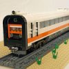
Hi to all, From the MTRkustoms factory we have the pleasure to present the ARDUINO AUTOMATED LEGO RAILCAR Here you can see the Railcar in detail This use modification pass the following phases PF --> 9v --> Arduino Control The original idea was very simple, have an autonomous and continuous Railcar in open circuits. I based the function in a great cheap invent, The Arduino Board, this small, easy programming and low cost, gives me the chance to make it real with a cost below 10€, including a PWM motor controller L298N Only 1 9v cable was "damaged" to convert its connection. The cycle work is very simple, Railcar goes from end to end regulated by the L298N with a PWM velocity. When the Railcar hit the final of the track (switch detection) stops 5sec and go to the other end and stops 10sec (and able to the passengers to go down) Time, velocity and stops time can be easy fixed by the programming. Some pictures of the system Stop No.1 Stop No.2 Switch Detail Cable connection boxes To hide the Arduino board and the L298N I made a modern prefabricated transformation Station Detail of the track connection Interior of the Transformation station All Full resolution pictures here A little video Enjoy it