Search the Community
Showing results for tags 'Technic'.
Found 1584 results
-

[WIP] Trophy Truck
unimog123 posted a topic in LEGO Technic, Mindstorms, Model Team and Scale Modeling
This is my first big project for this year. Here's what I have: As you can see, the rear axle still needs to be reinforced, so I was wondering if anyone as some solutions. Also do you think 2 L motors geared 1:1 to differential will be sufficient between speed and torque. -

Power Functions Motor Question
Commander Smith posted a topic in LEGO Technic, Mindstorms, Model Team and Scale Modeling
An order from Lego came in today, and I equipped my 42006 with 8293 and put two L-motors controlling the treads. Remote Control will come later. My question is: If you turn a PF motor manually, will that damage it? -
Life-sized hot rod driven by 256 Lego pistons
Hrafn posted a topic in LEGO Technic, Mindstorms, Model Team and Scale Modeling
The Lego Car Blog just posted a life-sized, pneumatic engine driven, Lego hot rod: -
[JFAIR] Biplane (WIP)
unimog123 posted a topic in LEGO Technic, Mindstorms, Model Team and Scale Modeling
This is what I'm making for the January-February Air theme. It is essentially a biplane, but I might add or take away certain things to make it unique. Here is what I have so far. I have come across a bit of a problem with the landing gear. I did not realize that the setup I was going to use with two mini linear actuators(front/back) doesn't work. They end up going in opposite directions. I may try changing the direction of the gears or using a worm gear solution. Also the gearbox in the cockpit will control the landing gear and hopefully the rudder. I would appreciate any suggestions. -

Lego TECHNIC Trial Truck
NXT45 posted a topic in LEGO Technic, Mindstorms, Model Team and Scale Modeling
Hi guys! I am new here so I wanted to show you my trial truck! http://nxt45.files.wordpress.com/2013/11/img_0705.jpg Full description & YouTube video on my blog: http://nxt45.wordpre...go-trial-truck/ (how do you post YouTube videos?) As always Happy building! NXT45 -
I'm an aerospace engineer living in the Seattle, USA area. I was a huge lego fan growing up but began a dark age after finishing school and beginning a career. I recently rediscovered my passion for legos and I've been buying mostly star wars and technic sets. The first time around, I had to build x-wings and starships with my imagination using random parts from space and castle sets.. It's an interesting change to see how things have changed since the 80s. Oh and I can't seem to figure out how to get any access or permissions to things like PMs. Is there something special I need to do?
-
Bugatti Type 35
landoandrews posted a topic in LEGO Technic, Mindstorms, Model Team and Scale Modeling
Here's my latest attempt at a race car: Bugatti Type 35. I built the body in more of a minimalistic design to reduce weight, and increase speed. The power is provided by two L motors, and the steering is controlled by a servo. https://lh6.googleus...E=w1233-h925-no The steering system is something I came up with. I don't think I've ever really seen this used before(please tell me if you've seen this anywhere else before),and it seems to work really well. In the video above you can see the steering in action. I'll post a video of it driving as soon as I can. -
1932 Luxury Roadster
unimog123 posted a topic in LEGO Technic, Mindstorms, Model Team and Scale Modeling
This is my luxury roadster. It is remote control with 2 L motors, servo motors, V2 receiver, and rechargeable box. You can visit my website here: http://legotechnicun....wordpress.com/ Then search "1932 luxury roadster" more information. -
Mini linear actuators are technic parts that mimic hydraulic cylinders and convert rotary motion into linear motion. They are primarily used in combination with power functions to perform minor mechanical tasks, but their scale suggests that they could be used to mechanize smaller town models as well, though I haven't found anything after a cursory search on this forum. I made these two models to show a couple of examples of how they may be used. The excavator arm and dump truck tipping mechanism both use mini linear actuators to add mechanical complexity to otherwise small and compact models. Here they are from another angle. Here the mechanics of the excavator are exposed. The boom is operated through a worm gear mechnism by the knob on the left of the "counterweight", and the arm is extended with the one on the right. Both mechanisms are geared so that two full revolutions of the knobs is sufficient for the full range of motion. I hope others might find these parts and techniques useful in their own builds!
-
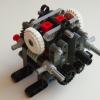
Hi I am working on gear pairs meshed directly together, in a 2 by 2 arrangement. Two gears on each of the two axles - However one gear is an idler gear which is driven by the other gears instead of with the same rotation speed as the motor. However I'm not sure if the ratio for the idler gear will be 1:1 since there is two 16 tooth gear gears in either example I don't think it is 1:1 though it should be what the other two gears are, so say 3:1 or 1.6:1 but I'm unsure as it's hard to tell. The yellow axle joiner goes to the motor, I'm using a differential to replicate a single 24 tooth idler in the first image. Obviously the dark grey gears are the idlers. Any ideas what it could be. More gears can be used with studed beams and plates such as 16 tooth +12 tooth or 20 + 20 or 16 + 20 etc. Regards, S
-

[HELP] Bevel Gears and Differential
nnamhcab posted a topic in LEGO Technic, Mindstorms, Model Team and Scale Modeling
i started a moc of a crawler trial type truck with a lsd (limited slip differential) which receives power from the motor through bevel gears that keep skipping and getting destroyed any help or suggestions would be appreciated i used an old style diff next to a clutch gear so the drive axle has some resistance only problem is the 16 tooth bevels won't mesh correctlly. -
 Hi everybody, Here is my review of 41999 4x4 Crawler Exclusive Edition "BOSS Crawler". Set that was coCreated by me and TLG. Hope you like the review. My reviews Full review Comparison review of 9398 and 41999 (use translate button at the right side of page under LEGO Technic logo). Comparison with 9398 Review from Masked Builder (eurobricks.com) http://www.eurobrick...showtopic=84293 Review from Anio (techlug.fr) http://www.techlug.f...us-kossman-2013 Review from Conchas (Technicbricks.com) Part I http://www.technicbricks.com/2013/07/tbs-techreview-24-41999-4x4-crawler.html Part II http://www.technicbricks.com/2013/08/tbs-techreview-24-41999-4x4-crawler.htm Official Building Instructions: http://cache.lego.com/bigdownloads/buildinginstructions/6064360.pdf http://cache.lego.com/bigdownloads/buildinginstructions/6064367.pdf http://cache.lego.com/bigdownloads/buildinginstructions/6064368.pdf http://cache.lego.com/bigdownloads/buildinginstructions/6066063.pdf
 -

[WIP] Shock(and kids)-resistant Helicopter
paulblda posted a topic in LEGO Technic, Mindstorms, Model Team and Scale Modeling
Hey everyone, this is my very first MOC presented here on EB. This MOC's goal is to entertain my 3yo neighbour, therefore it should be shock-resistant and child-proof. Also the propellers will rotate as the heli's wheels rotate (while the heli being pulled on the floor of course). Maybe I will change the colour-scheme, but most of my spare parts are in black, so this is what it will probably look like. Comments are of course welcome. I can add the LDD file, if wanted. -
Ping Pong Server
landoandrews posted a topic in LEGO Technic, Mindstorms, Model Team and Scale Modeling
Here's my latest project: -

Supercar Chassis - Crowdsource a Supercar
Ape Fight posted a topic in LEGO Technic, Mindstorms, Model Team and Scale Modeling
Technic Supercar Chassis - Crowdsource a Supercar? Hello Eurobrickers. I've had an idea that I was wondering if I could run past you, especially those of a Technical persuasion. There are some amazing Technic supercars on the 'net from the like of Crowkillers et al, and I think many of us would love to build something comparable. I think many of us also secretly harbour the ambition to be a car designer or Lego designer. I'd like to see if this idea would interest anyone who has the above ambitions: Could we build a modular Technic Supercar together, from people based all around the world? Real cars are designed in a modular method, often with internal competition between design studios and teams to 'win' the right of their design being used in the production model. For example, Mazda's MX-5 design was chosen from a variety of their design studios, with the California studio design selected for production. Toyota's revolutionary Hybrid system was chosen from an internal competition to design a power-train with 50% improved fuel economy. Do you think we could do the same? I've designed a modular chassis architecture, featuring independent double wishbone suspension, rack and pinion steering, a 'flat' automatic (D-P-R) gearbox, Power Functions compatibility, modular engine options from an I3 to a V8 and variable front and rear overhangs. Track and wheelbase are fixed. It requires: Engine designs; using any configuration within a 4-cylinder length, turbocharged or supercharged, full hybrid or KERS Dashboard and instrument designs, including steering wheel adjustment, pedals, centre console etc. Seat designs for folding and adjustable seats front and rear Bodywork designs; for a GT, sports, or 2+2, convertible or coupe Door and other aperture designs; conventional, suicide, scissor or gull-wing Exterior light designs; fixed, pop-up, LED etc. Each of these would have a range of criteria that must be met (e.g. Weight, Cost, Parts Availability, Functionality etc.), after which the most suitable designs would be selected and built for the Supercar. If (a very big 'if'!) this were to work at the end of the project we'd have (hopefully) a top-spec Technic Supercar, designed and built by people from all over the world So, for those on MOCpages and Flickr, do you think this could work, and if so would you be interested in designing elements for the final car? If it doesn't work I'll just carry on and build the whole thing, and I'm sure I could do a good job. But I think the talents of many builders will result in a great job, not just a good one. Please add your thoughts below! Ape -
Merry Christmas to all!!! My minifigs like this winter ferris wheel very much! Want to see it in motion?
-

[MOC] Rescue Brigade
legosamigos posted a topic in LEGO Technic, Mindstorms, Model Team and Scale Modeling
Some mini MOC :) -
[MOC] Lego Technic Bronto Skylift
legosamigos posted a topic in LEGO Technic, Mindstorms, Model Team and Scale Modeling
Hello Eurobrick members! Today I would like to show you the Bronto Skylift. Bronto Skylift is the global market leader in truck mounted hydraulic platforms. The company designs, manufactures, sells and services platforms meant for rescue and fire fighting as well as for any construction work. I wanted to show you some functions from real Bronto Skylift, Specifications Length – 67 cm Width – 19 cm / with outriggers – 27 cm Height – 24 cm / max. height – 87 cm Weight – 3.7 kg Power Functions Drive – 1 PF XL motor 4 steering axles – 1 PF M motor Narrow jacking – 1 PF M motor Full jacking – 1 PF M motor Lifting boom – 1 PF L motor Extension boom – 1 PF L motor Lifting cage boom – 1 PF M motor Rotation 360 degrees – 1 PM M motor Extra Power Functions 2 x PF battery box 2 x PF extension wire (20 cm) 3 x PF IR remote control 4 x PF IR receiver BS Gallery -
[pid][/pid] Capstans Welcome at my first tutorial here at Classic Pirates, in this tutorial I will try to convince you that there is no argument not to have a functional capstan on your ships. (On condition you have a ship big enough to support one ofcourse and I heard some people are allergic to Technic so I guess that's a valid argument as well). This working capstan design applies perfectly for a frigate in CGH style. I will use a prefab hull for this tutorial but I want you to keep in mind that it can easely be applied to costum hulls as well. This guide will be quite basic because there just are so many different ships, every ship needs its own approach on how to integrate a working capstan. I will start with a simplified construction of a capstan used to haul a singe anchor, then I will extend to more complex and versatile mechanics to eventually allow you to operate two independent anchors. So without further ado, let's get this party started. Operating 1 anchor: You'll need a capstan, it doesn't have to be this one but make sure it connects to a cross axle. But if your really want this one... Another capstan: By Phred An anchor with a winch (also cross axle based). You can use the capstan for other things besides the anchors as well but I'll get to that later. Some usefull technic parts; This is a useful construction; But if you don't have the black part you can use this alternate construction; Now... The implementation of a working capstan takes place at the very beginning of the ship-building process. It's important to place the capstan at the best location of the ship. When starting a new ship I usually start by marking the locations of the masts (I covered them with green round plates to make them more visible). Yellow marks the possible locations of the capstan, keep in mind that the capstan has a volume too so you'll have to reserve some space near the masts. To decide where you will ultimately place your capstan you should consider what else you want in your ship, a staircase and grates perhaps. AT this point you have to know (more or less) how the deck will look. Personally I find it most practical to place the capstan just behind the second mast (on a three mast ship that is), that way I have plenty of room for grates between first and second mast. What I'm going to do now is probably not historically accurate. I will not connect the anchor winch directly to the capstan. I do this for practical reasons, you don't want anchor cables running through the ship, trust me. What I'll do is much more reliable, the anchor winch should be placed as close to the bow as possible (as close to the place where the anchor will hang from the ship), this way there's less chance of complications with rope/cable getting stuck within the ship. Instead of a direct cable connection I will make use of a flexible axle. First attach the capstan to the construction mentioned earlier (this is temporarely, you can detach it later to work on the deck and so on). Then you place this construction in the ship on the place you wanted the capstan (the main reason to attach the capstan already is to make sure it doesn't interfere with the masts). As you can see the capstan is connected to an axle running through the ship. Technic bricks are useful to run through the masts and other obstructions. You may wonder what's the universal joint is for, I noticed some of my ships tend to bend a little when building larger, the joint assures a smooth axle turning. Now the anchor can be hauled up using the capstan. Operating 2 anchors independently: Now in order to provide multiple independent functions to one driving axle, operating two independent anchors with one capstan for example, you'll need a mechanism to shift gears. LEGO Technic provides us with a very easy-to-use system consisting out of these key-parts: Clutch gears: Gear 16 Tooth with Clutch (you need atleast 2). Driving Ring: Driving Ring (you need 1 for each pair of clutch gears). There's also a technic switch available which makes it easier to make the driving ring hatch into the clutch gears: Changeover Catch But I've seen multiple alternatives for that part at the Technic forum, still, I like to use this part over alternatives. In this picture you see the left gear clutched to the axle on top, neutral in the middle (no gears clutch) and right gear clutched at the bottom. connecting the clutch gears with other gears allows you to operate multiple axles, I will now integrate this system in the hull; Note that I just picked a random position of the 'gearbox', you can easely place it practically anywhere, in front of/ after the capstan, in the bow (like I did for my Frigate. Again it's important to think about how your ship will look and what features it will have when choosing a location for the gearbox (The switch was taken out for a better view) The red axle connectors are used to block the gears in one direction, this allows you to pull an anchor while preventing it to fall back down. This isn't always needed though, usually, because the official anchors are so light, the friction alone is enough to keep them up. I used yellow axle connectors to show how to operate the switch, as you can see the lower one allows a rotative motion to switch gears, this means you can attach this end to another flexible axle and thus move the location of the switch away from the gearbox. To illustrate how it works I made this short video: UPDATE: 21 December 2013 The previous construction was built very symmetrically so it would be easier to see how it works. However, when applied to a real MOC ship you don't need to see how it works, the more compact you can build the mechanism, the more space you gain for interior and/or other functions on your ship. I have therefor applied this capstan mechanism to a current WIP of mine to show a more practical example. This is a three-mast ship, the capstan is located after the foremast (very common location for the capstan on a historical ship). The capstan itself will be mounted on the brown vertical axle. The red axle connectors with gray axle towballs are used to block the anchors in place (so they don't fall down after you hauled them). As you can see the gearbox for switching anchors does not lay in line with the ship's length this time. The switch itself is concealed under the yellow technic plate and will be operated by turning the light grey axle. I intend to attach a barrel to the switch axle to hide it on deck in an elegant manner. On this picture you can see the anchor blocking mechanisms, these are connected via several gears to the previously mentioned axle towballs, which will be accessible on deck. Sigh, I really don't get it, when I watch the movie on my camera it's great but when I upload it to my computer it becomes dark . So, this was it, for now. It's my first tutorial so ofcourse it's not perfect, any suggestions to make it better are welcome as well as questions (which may inspire me to expand this tutorial or explain part in a different way). Combine this tutorial with Build a frigate with Captain Green Hair! An interesting link for more about capstans; Capstan by Foremast Jack - - - - - - - - - - - - - I will expand this tutorial later with a sollution for modular ships (yes, a modular ship is not a valid argument not to have a functional capstan so if DPW is reading this... ).
-

Alignment of Technic pieces in MLCad
Adam Badura posted a topic in Digital LEGO: Tools, Techniques, and Projects
Until few days ago I was using Lego Digital Designer to build some models from time to time or to play around with some ideas. But since I hit an obstacle of missing parts more often than I would like to I decided to try something else. By the way I don’t quite understand where is the problem in adding all Lego pieces to LDD. I guess it is lack of “human resources” to do that job. But if so then why not open data format and allow fans to add the parts they miss, post them for a review or something so that on the Lego side of the task it would be much less work. Or maybe there is some programming needed around new pieces and thus the work cannot be released to public without actually releasing entire project. Anyway I’m dragging here myself from the topic so lets get back to the issue. I started with MLCad as from a quick “look around” it seemed a good starting point and quite popular. I gave a short try to LeoCAD but didn’t see any significant difference here. Then also SR 3D Builder which seemed to have advantage of auto-alignment of pieces like axles. But since it is under development (the one that installs with LDraw All-In-One-Installer doesn’t even work due to some integration issues – what is the point to include it that way?) and non-free I stopped exploring it (for now). But trying to do a model from instructions I had on paper I really struggled with MLCad. It is FAR more difficult to work with it than with LDD (at least for me – lets state here that I don’t have any CAD experience). And the most difficult part is to align pieces. As it comes to standard bricks the “Coarse Grid” seems to be good enough (but still alignment has to be done manually). But since I chose a Technic model obviously soon I came across pins, axles, bushes and holes. Aligning that still seems to me more of an art than science. (That is why I decided to give a short try to LeoCAD and SR 3D Builder.) I think that somehow I made it. Or at least it looks good enough on the 3D view. But I’m not entirely sure. Is there a way to verify model? If it is physically proper? That I haven’t move a pin one step to far for example? Can it be done automatically? Are there any tools to verify if model honors various building rules (like not stressing pieces too much)? And since I’m already writing then some side questions: Is it possible to move the camera rather than the model in the 3D view? That way it might be easier to see some details within the model? Is it possible (maybe in some external application) to animate MLCad model? Are there any open source editors for LDraw? -
Hello, my name is unimog123 and my models consist of lego technic. I will be posting my models soon.
-
This is my first model entry, there will be many things to come, though. This is a Honda CRF 400 dirt bike. It feature a chain driven 1 cylinder engine and rear suspension. This was the original model.
-

Technyk32231's MOCs, WIPs, and ideas
Technyk32231 posted a topic in LEGO Technic, Mindstorms, Model Team and Scale Modeling
Ok, here is a gearbox I made. It was made to be realistic, so it only has two shafts, one for input, the other for output. I had to make two types of gears myself, a 20 tooth clutch gear and a 24 tooth clutch gear. The 24 tooth clutch gear was cut off of an old type differential, and the 20 tooth clutch gear was made by hollowing out the center of a regular 20 tooth double bevel gear, cutting the teeth off of a regular 16 tooth clutch gear, and putting the 16 tooth inside the 20 tooth. The gearbox is a 6 speed + 2 reverse gearbox, so 8 gears total. Really though, it's a 3+R gearbox hooked up to a 2 speed transfer case. http://www.brickshelf.com/gallery/technyk32/Miscellaneous/Forum/img_20130531_072212.jpg The picture is too large to embed, and sorry for horrible quality, it was taken on my mobile, and gearbox is long disassembled. Maybe sometime I'll rebuild it and take better photos. Here is a car I made a while ago to teat steering and suspension. I lost the shot where it isn't upside down, sorry. These photos were also taken on my mobile. I'll take more pics of the front axle later, the model has already been disassembled, but I kept the front axle for future projects. These photos are also too large, so I'm putting links. http://www.brickshelf.com/gallery/technyk32/Miscellaneous/Forum/img_20130522_070614.jpg This is a good WIP photo, taken of the first version of the front axle. Later, this axle would lose the shock absorbers and gain improved steering geometry and suspension travel. http://www.brickshelf.com/gallery/technyk32/Miscellaneous/Forum/img_20130528_071434.jpg This is the new front axle. The vertical 6L link is for suspension. This model has all-round floating solid axle suspension with transverse torsion bars. As you can see, this new front axle has caster angle. I couldn't get the shock absorbers to work correctly, and I wasn't satisfied with the suspension travel, so that's why I switched to torsion bars. It works very nicely. The caster angle is achieved by simply moving the upper links backwards. The front suspension is a triangulated 4 link type, and the rear suspension is a 3 link with a bionicle ball joint. This model has no fake engine, as the main focus of this model was steering and suspension. Plus, the front suspension took up too much room for a fake engine. http://www.brickshelf.com/gallery/technyk32/Miscellaneous/Forum/img_20130528_071406.jpg Here is the underside shot. The center of the model is held together by the floor and "doors" entirely, forming part of the central body, almost like a unibody construction. Oh, and here is just a strange mechanism I made. As the input rotates, the output "punches" in and out. http://www.brickshelf.com/gallery/technyk32/Miscellaneous/Forum/img_20130612_072035.jpg -
[Discussion] 3 Wheeled motor bike
Doc_Brown posted a topic in LEGO Technic, Mindstorms, Model Team and Scale Modeling
I stumbled apon this beauty, and after examining it can not work out how it would work (steering mostly) unless its some sort of CV joint. I'm curious to know from those that know bikes (and ridden one! :P ) What you think of this. Also its potential to build in technic. -

[MOC] Container Truck
pbeishuizen posted a topic in LEGO Technic, Mindstorms, Model Team and Scale Modeling
Some picture of one of my first MOCs since coming out of the dark ages. At least the first I'm confident enough to post, although I'd like to spent some more time on the detailing. Had it standing around for something, and got triggered by the 2014 news to finally post it. PF container truck: powered by 1 medium motor. 3 gear levers, each allow a function to operate in both direction independent of motor direction (switch on the battery box blocked in 1 direction such that the direction of the levers corresponds with the direction of movemen): - outriggers at back: can be used to raise the rear axle (just) of the ground for stability - left and right arms moving together or separately (to correct for misalignment of container when picking it up). Cabin inspired by the TLG blue container truck (8052), but made 2 studs wider and with modifications for especially the wheel arches. looking forward to your thoughts and comments.