Search the Community
Showing results for tags 'Power Functions'.
Found 368 results
-
Ketchup & Mayonnaise Factory Hi, Lego funs -- I built this Factory (machine) for my grandchildren Filip & Laura to have more fun in preparing their small Christmas ham and cheese sandwiches with spread of ketchup or mayonnaise, as they like. As you can guess, there is a lot of fun, although they eat (and play) 60 minutes longer (but eat more). A short video will be posted in a day Mladen. And two action shoots: - http://bricksafe.com...orkan/K&M56.jpg - http://bricksafe.com...orkan/K&M57.jpg
-
Lego technic electric function switch - max. 24 motors to control
Tamas Juhasz posted a topic in LEGO Technic, Mindstorms, Model Team and Scale Modeling
Hello! I had an idea nowadays how to control a lot of PF motors without very complex and space requiring mechanical switch: http://www.brickshel...ry.cgi?f=537994 The conception is simple: I used only electric components to switch between the motors. There is two receiver blocks, each contains 3 receivers. The fourth receiver has the swicthing motor, and the 13th motor can be connected to the other output. So the system in the pictures can be control easily 12 + 1 motors. One advantage is that the switching itself is very fast. If you connect two switching motors to the 4th receiver, you can use 24 motors. Indicator LEDs are recommended, so you always can see, which block (=which functions) are switched on. The blocks can be switched on individually, because the controller motor(s) pushes the battery box's on/off button. To control 13 motors, you need 7 receivers, 3 battery boxes, and 1 M motors. To control 24 motors, you need 13 receivers, 5 battery boxes and 2 M motors. I don't think the amount of PF parts is a problem. If somebody makes a huge moc with so many motors and functions, then 7 or 13 receivers and 3-5 battery boxes aren't so much in money and requiring space. A lot of builders are still have these. More pictures: Video: Hope you like it. Edit1: I forget to say, you can't switch off the receivers through PF switches. At the beginning, I thought at switches and one BB, but it's simply doesn't works. Each block needs a battery box, the receivers can only switched off with them. -
RC Liebherr LTM 1090 mobile crane (62 mm wheels)
Tamas Juhasz posted a topic in LEGO Technic, Mindstorms, Model Team and Scale Modeling
Hello! I'm finished with uploading and lot of work, you can see one of my biggest and most complex moc. I always loved mobile cranes, so I decided to make a Liebherr LTM 1090 with medium sized (62,4 mm) wheels: folder with bigger pictures: http://www.brickshel...ry.cgi?f=533546 big montage: http://www.brickshel...90-62mm/002.jpg boom: http://www.brickshel...ry.cgi?f=533548 details: http://www.brickshel...ry.cgi?f=533547 About the mobile crane: Every function is remote controlled: - driving (1 XL motor) - steering (1 M motor) - outriggers outcoming and legs moving (1 pneumatic circuit with rubber band "control", 1 M motor for pneu switch) - upper structure rotating - boom raising - boom extension - winch (hook) - compressor for making pressure - front lights (together with driving (and steering with "turn signals") ) After outriggers, these functions are working also with one M motor, or directly from the receiver's output. Dimensions: Length: 610 mm Width: 135 mm Height: 211 mm Scale: 1:20,5 Dimensions with raised and extended boom: Length: 1235 mm Height: 1260 mm Other dates: Number of pieces: 3433 Weight: 3460 g Building time: 23 days Speed: first gear: 0,14 km/h second gear: 0,23 km/h third gear: 0,38 km/h fourth gear: 0,55 km/h Maximum boom extension: DETAILS: Flashing light in the back (made with two light brick, but one is covered with that black piece): Lights: Exhaust: Instrument panel: Manometer (for seeing the outrigger's pressure) and gearbox (manual) cover (the dkbluishgray one): You can use the airtnak in the pneumatic system, or not, depends on these two pneu valves: http://www.brickshel...90-62mm/024.jpg Truck The truck part is an 8x8x8 driven construction ( http://www.brickshel...y.cgi?i=5936235 ), with a manual gearbox and One Xl motor for drive. The outriggers are working with pneumatic, as can be seen in the pictures, one motor with pneu valve is enough for control, because the backward movement is done with rubber bands. The pneumatic system is enough strong to pull out the rubber bands and lift the mobile crane's own weight. http://www.brickshel...y.cgi?i=5936260 - I simply wanted to try out this solution (the original also has also a clyinder to push out the legs). It doesn't works 100%, sometimes a little help is needed to came back. The motorized pneu valve isn't my idea, I saearched a lot to find the designer, but it wasn't success. A compressor makes pressure in the aritank (or directly to the legs, see the description above), then the valves can be opened or closed. The PF system has 8 channels overall, so some functions are together with other ones, like the front lights with steering. One PF led is for light. Crane part (upper structure) The most important in this part is the strenghtening in the turntable, I made it with 4 pulleys, and 2 mm width rubber bands (O rings): http://www.brickshel...y.cgi?i=5936256 Works, well, in extended state the boom doesn't deforms the structure. The 4 pneumatic cylinder can raise the quite heavy (3 section) boom, but not in extended state (as most of the originals). The whole boom can be extended up to 1260 mm height. The backward movement is done with strings, not with gravity, it's more reliable. One small Li-Po battery can power the machine, this black button is for power on/off: http://www.brickshel...y.cgi?i=5936219 http://www.brickshel...90-62mm/004.jpg - you can switch after the operator's cabin with the dkblgray pneu switch to raise the cabin in angle or not (done with one little pneu cylinder). This video can tell more than me, it took me a time to make it, but it's necessary for this model: Hope you like it. Maybe I didn't write everything, feel free to ask, if something isn't clear. -
I've spent the evening building a Pannier Tank Engine. it doesn't run, as I haven't put an IR receiver or battery box inside it yet (I'd have to take them out of my Constitution train), but there are 'dummy' ones in there which I built out of bricks so I had something to work around. It's sat on top of the PF train motor (I removed my Constitution tender from the motor temporarily) to see if it would sit on it well, which I think it does. In the second photo you can see how it's meant to sit on it, and how most of the body is basically built onto the (dummy) battery box. There should be enough space for all the wires... What do people think? Can you see any potential issues or problems? Looking at it now, I'll probably lower the roof by one plate, and I might replace the windows with something else. I'll probably do other stuff to it as well, but for an evening's work, I'm quite pleased.
-

Worth the cost to get into 9V now, with a huge investment in PF?
Locutis posted a topic in LEGO Train Tech
I have a substantial (in my view) investment into Power Functions trains and track. I currently have about 12 modern PF trains, and about 100 feet of plastic PF track. I have many remotes, motors, etc. Our group, MBLug, just finished our second display show (my first), and I was very "envious" of many of the electric trains. In addition, I had to borrow track to go through my section as I do not own any 9v track. My section was 16' long, with 2 rail runs through it. My question is simple: Is it worth it to now go back and buy some 9v trains, track, and accessories even though I have this significant PF investment? I'm a purest to a point (I will bricklink build something that is difficult/impossible to get), and would consider getting pieces to build a Santa Fe or BNSF or Metroliner without making them 9V, or buying them and converting to PF. Should I convert my PF trains to 9v, and pickup some older 9v trains and track, or should I buy older 9v trains (without the track/etc.) and convert them to PF? The only problem is, by staying "modern", I'm kept out of the displays. My trains are all battery-operated, and the LUG show co-ordinators insist on 9v only, which means none of my fantastic trains can be put on display at a show here unless I convert to 9V (which I currently have no means to do). What's your opinion? How have you or your LUG handled the (no longer recent) transition from 9v to PF? Locutis -

[MOC] Huge NXT Ball Machine
Purple Geek posted a topic in LEGO Technic, Mindstorms, Model Team and Scale Modeling
This LEGO ball machine was constructed using 10 motors and thousands of bricks. Its 14 balls move continually through the machine, taking approximately two minutes to complete a lap. Two Mindstorms NXT bricks control the green lift, blue lift and ball counter. A combination of Power Functions and traditional 9V motors drive the remaining lifts. The machine is built entirely from LEGO -- even the balls are LEGO parts. Width: 63.5 inches Depth: 24 inches Height: 30 inches A video showing the machine in action is available on YouTube: Let me know what you think! Ben -
My recent build is this suburban passenger train. It is not a replica of any real rolling stock, though the design and livery are roughly based on UK train operator South West Trains. The train is an electric multiple unit, consisting of three units. A driver's cab is located at both ends of the train. Unlike the model mentioned above which draws electricity from third rail this train picks it up from overhead line. The train is 96 studs long. Counting also the bumpers and coupling magnets which protrude slightly beyond the construction, the entire length is 99 studs. The driver's cab is virtually completely snoted. Actually this technique left a slight aesthetic flaw – cutouts at the end of the roof above the cabin. Front end The interior of the front car with segregated driver's cab. The same design is employed in the rear car, with the only difference being the fourth passenger seat which is missing here beacause of the placement of the battery box. Though the train appears to be supplied with energy from external source it still needs some standard PF components for independent motion. The IR receiver and battery box are placed in two different cars which allows easier masking of the compoments and better utilization of the passenger compartments. The motor is placed under the middle car. The interior of the middle car The pantograph is not completely my invention but I used the design that has already appeared in some creations here on Eurobricks.
-
Hi In my first posting i want to show you a little MOC from last year. It's a small PF scissor lift. Last week i made some photos in the garden. Here's a short video of it: That's it, i hope you like it. Greets from Germany, Heiko
-
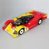
Hi everyone, This is my Lego 42000 Grand Prix Racer full RC mod Features: - 2 L motor for driving the rear wheels - 1 servo motor steering with working steering wheel - 1 M motor for wing adjustment - 1 M motor for opening the engine cover http://www.brickshelf.com/gallery/imurvai/GrandPrixRacerRCMod/img_20130325_211618.jpg sorry, I accidentally post the previous one only with one picture. so, here are some more: http://www.brickshelf.com/gallery/imurvai/GrandPrixRacerRCMod/img_20130325_211802.jpg http://www.brickshelf.com/gallery/imurvai/GrandPrixRacerRCMod/img_20130325_211651.jpg and a short video:
-
Another larger project is under way and the first part of it is the rail turntable. An essential part of railway infrastructure in the era of steam traction but unfortunately not very common these days. The concept is fairly basic - a bridge for rotating the engines, or in this case to direct them to one of the rails leading to the roundhouse. Side view The drive is hidden under the rails. The turntable is powered by M motor which is powerful enough to rotate the bridge with Emerald Night on it. A video of turntable in action is shown . The entire thing is built on six 32x32 baseplates and the pit is 58 studs in diameter.
-

simple lightweight rally car
nnamhcab posted a topic in LEGO Technic, Mindstorms, Model Team and Scale Modeling
so i've been reading around on the forums trying to find a design plan for a simple lightweight rally-ish car and i decided to just try it myself i just finished tonight and ill have pictures uploaded soon if there are any other topics that meet these criteria post them below thanks -
Land Rover Series I RC model
Tamas Juhasz posted a topic in LEGO Technic, Mindstorms, Model Team and Scale Modeling
Hello! After some weeks there is my newest publication, a Land Rover Series I model. I'm planned to make a real off-roader long ago, with this I wanted to build a realistic one with realistic looking chassis. It could be another famous off-roader, but this is the first Land Rover, and it matters me a lot. So the moc: http://www.brickshel...ry.cgi?f=531411 Wheels, motor, gearbox: This wheels are made from the 81,6 mm tyre and from the 56 mm wheel. This is enough narrow yet to make this model with it. The model has the standard four speed gearbox with my definite control (see my other topic for more). This model was built a few month ago, that time I didn't have my improved gearbox with the same function, but this also did it's job, at last it didn't came so much load, there is a gearing after the gearbox. One RC buggy motor is there for propulsion (the noise is it's noise - don't ask me about that, this is the standard noise of this high rpm motor). I used that because of it's high rpm, there is a lot of gearing after that including the low gear/high gear gearbox. In this model, my goal was to make a realistic looking car with a realistic looking chassis and technic, performance was secondary. With the secondary gearbox there is in all 6 speed (two is the same). Sometimes in low gear, but it goes everywhere. Chassis, suspension: The chassis is a single ladder type one, with strenghtening beams an plates. The chassis itself contains every working mechanism: The suspension is made from technic axles, to be like leaf springs, and it works like that. There are positioning links to hold in the right place the axles. A small 6 L link holds transversely the front axle. I made the housing of the differential in the rear axle: http://www.brickshel...y.cgi?i=5898328 The steering, as in the real one isn't made with gear rack, but with a linkage-like machanism. The suspension performed surprisingly good on terrain. Has handbrake, it prevents roll down in forward direction. All function is remote controlled, the on/off switching of the low gear and winch also, by two micromotors. Under the hood I placed a 4L "fake" engine: http://www.brickshel...y.cgi?i=5898334 Body, etc.: Basically the body is a simple plate body with some liftarms and bricks. Of course, the front part was the hardest section. This front look means the Land Rover itself, very easy to recognize. I tried to add many details to the body, like mirros in the left side, turning lights, number plate, door handle to be less monotonous. Inside there is a big cover from a western set, we can find under that cables and technical parts. The steering wheel works, with these old bushes: It has an advantage: the turning is smoother than U-joint drive. Except this it's only an interesting technique, typically for applications which aren't require much torque. Video: (intro is also off roader-like, I didn't find a flat surface) Main specifications: Weight: 1555 g Speed: high gear: 1: 0,50 km/h 2: 0,82 km/h 3: 1,25 km/h 4: 1,67 km/h low gear: 1: 0,19 km/h 2: 0,32 km/h 3: 0,56 km/h 4: 0,92 km/h Length: 387 mm Width: 192 mm Height: 198 mm Scale: 1:9 -
lightweight power functions buggy
nnamhcab posted a topic in LEGO Technic, Mindstorms, Model Team and Scale Modeling
I've refined this model many times and this is the final version. a simple buggy powered by two medium motors rear wheel drive with diff its pretty fast and does alright off road a simple modification to the design could allow for an xl motor to be put in and geared up. in the model the steering rack sits in the slot at the front of the vehicle and connects to the 1x6 links and the two 1x8 axles connect in the front to form the tube body frame. i also couldn't find the ir reciver it attaches to the pins that are on the roof of the buggy and hangs upside down and inside the frame work. other than that its complete. buggy.lxf -

Custom Lego Hot-rod Hearse
octavspot posted a topic in LEGO Technic, Mindstorms, Model Team and Scale Modeling
This is a bit of an older MOC I did last Halloween - (it's long scrapped now) but I thought I'd share this here as well - especially for those with a small taste of the macabre. Just after building Lego's Vampyre Hearse, a new, slightly-morbid-yet-cool idea spawned in my mind; what if I build a bigger, RC version of this? At first, I wasn't quite sure what it'll end up looking like, since I couldn't figure out what to model it after - a Cadillac? a Rolls-Royce? a Lincoln? - so, I went with all three - sort of, lol. Hearse Front by Octav_spot, on Flickr What's interesting is that the headlamps are actually yellow elements, but mixed together with the blue from the LED's, it came out green. I liked the look so much, I kept it as is. Hearse Rear by Octav_spot, on Flickr The side-lamps idea came to me in the last moment - I wish I'd of made them look closer to actual lanterns (since that's what original hearse carriages had.) To my surprise, the light came out looking almost purple, which seemed strikingly accurate. Hearse Profile by Octav_spot, on Flickr Two Hearses by Octav_spot, on Flickr Just the V8 engine itself was literally half the Vampyre Hearse. I laughed. Hearse Speed by Octav_spot, on Flickr To see it in motion, here's the video. I thought the reaction from my cat was pretty funny, so I kept it in the clip Currently working on an actual Rolls Royce... just haven't decided what model year yet... In any case, enjoy! -
Attention all Brickworld train enthusiasts... We are pleased to have a Train Technology presentation at Brickworld Chicago on Friday, June 14. Name: "Building Techniques: Train Technology: Realistic Ballasting, Switching and Operation" Presenters: Steve Jackson, Cale Leiphart, Nate Brille Description: The PennLug team will present advanced techniques for Ballasting track, Remote Power Functions decoupling in a locomotive, NXT trolley control, and Prototypical Yard layout and operation. Samples of ballasted track and working locomotives will be available for viewing. Please join us in Chicago if you are coming !
-
Well I thought I would post the results of my efforts today, nothing special but my son decided to get the monster fighters ghost train set with some of his Christmas money, and after he finished building it this morning he instantly said to me "can we add power functions daddy?" So here is the result, the other side isn't complete yet as I didn't have enough parts, I also had to raise the front by one flat so that the flangeless driving wheel didn't derail the train on the exit from bends, can't find a better solution for that yet! Let me know what you think! Cheers, Dave
-

Arduino and PF Motors
peter_m posted a topic in LEGO Technic, Mindstorms, Model Team and Scale Modeling
Hello! My Rescue Helicopter (9396) is about to be delivered ( ) and I have this idea to put enormous amount of LEDs in it. I have a plan to use Arduino to program proper blinking sequence. I was thinking about mounting also 2 M-motors to motorize rotor and functions. I would love to control them via Arduino but I do not have an idea how to connect motors in a proper way. Has anyone ever done it? Thanks in advance for any tips! -
As models are now starting to get finished for a show in a few weeks time, thought I'd share them here. This is my first model using Power Functions. Its been made to allow quick easy access to everything needed and despite in theory the fact the rods "should" throw themselves off after a minute or so of running, they dont! No idea why but its been working fine. I suppose any real problems will arrise at its first public event, as Murphy's law states thats when they always happen! I'm still undecided about the rod colour, hence a rough red sticker is covering one until I make a final choice. Link to Flickr set and more details:
-
I have submitted a new project to LEGO Cuusoo, an inductive charging system for Power Functions trains etc... The idea is that the train would stop over an inductive pad, similar to the ones available for phones etc... but tailored to fit between the rails. It could be placed out of sight in the through-sidings of a fiddle yard so that one train would run while the others charged up. I would like this to become a single LEGO piece similar in size to an IR Receiver i.e. 4x4 with a flying lead. The same coil device would be used under the track and on the train. This is the simplest possible form and probably the cheapest too. I would equip all the sidings in a fiddle yard with coils (perhaps 10 on my layout) and each train (maybe 16), so 26 coils in all. I hope each one would not cost any more than an IR Receiver. It would also have application for Technic and Mindstorms, so making the same piece work in all markets makes it most viable. Please follow the link, support, leave comments and spread the word! Thanks, Mark
-
Mini RC Tatra 813 - 8x8
Tamas Juhasz posted a topic in LEGO Technic, Mindstorms, Model Team and Scale Modeling
Hello! My newest mini moc is also a Tatra. My goal was to make a 8x8 813 model with realistic Tatra suspension: This was my first moc, which could be build with 1:1 scale from a paper: I always wanted to build a really small Tatra with the wheels from 8842. This wheel has a diameter of 43 mm, so the proportional width is about 11 stud. That's even not enough, too narrow, but I had success with the suspension and drivetrain in 13 stud width. The first and second axle has steering, and all axle is driven and suspended. With U-joint there is no way to build it narrower. I used 3 different shock absorbers. The first axle has harder ones to hold the weight reliable in the front. The steering mechanism only steers directly the left wheels, the right ones are steered by the 9L links: http://www.brickshel...y.cgi?i=5748589 The ground clearance enables 25 mm high obstacles under the truck. Of course it can go through much bigger ones, as can be seen below in the video. The drivetrain is pretty simple Tatra like, with assimmetric left and right side: http://www.brickshel...y.cgi?i=5748587 In the picture it also can be seen that the front 4 wheels are driven with a small 2L thin liftarm to prevent clacking(if it uses pins and pulley). There wasn't problem with that, in every terrain kept the front wheels the correct position. They look like the valve cover of the wheels.( I forgot to take them also in the rear wheels) Maybe from the pictures we can think that the 12 bevel gears can go out in the middle of the axles. They can't. The 2L red axles prevent that (I used strong 12 gears and loose U-joints). The suspension worked well in terrain, this Tatra doesn't carries tons of weight, stronger axles aren't necessary. The wheel travel is about 2 stud or a bit more depending of the axle. Technic inside: http://www.brickshel...y.cgi?i=5748652 The steering M motor is in the front, the driving M motor is in the rear part. The M motor is powerful with 6:1 final ratio. It can be, because the weight is only 761 g. The stability surprised me. In the video can be seen some test. The aesthetics was also important for me, this one isn't a trial truck, more civil version. I had to cut the mudguards to give space for the wheels, and of course it's a bit higher than the real Tatra to have wheel travel. The front grill has a Tatra logo and some covering sticker: The on/off button is in the top of thew vehicle: If you hit the PF connector, the front LED lights will work(video). I didn't want a PF switch, and wanted to try this out. And the video with infos: If somebody needs, I can upload the building instructions. -
Three state remote controlled pf switch without using the pf train rem
jacobkristensen posted a topic in LEGO Technic, Mindstorms, Model Team and Scale Modeling
jjjjjjjjjjsaaaaaaaaaaaaaaaaaaaaaaaaaaaaaaaaaa jjjjjjjjjjsaaaaaaaaaaaaaaaaaaaaaaaaaaaaaaaaaa jjjjjjjjjjsaaaaaaaaaaaaaaaaaaaaaaaaaaaaaaaaaa jjjjjjjjjjsaaaaaaaaaaaaaaaaaaaaaaaaaaaaaaaaaa jjjjjjjjjjsaaaaaaaaaaaaaaaaaaaaaaaaaaaaaaaaaa jjjjjjjjjjsaaaaaaaaaaaaaaaaaaaaaaaaaaaaaaaaaa jjjjjjjjjjsaaaaaaaaaaaaaaaaaaaaaaaaaaaaaaaaaa jjjjjjjjjjsaaaaaaaaaaaaaaaaaaaaaaaaaaaaaaaaaa jjjjjjjjjjsaaaaaaaaaaaaaaaaaaaaaaaaaaaaaaaaaa jjjjjjjjjjsaaaaaaaaaaaaaaaaaaaaaaaaaaaaaaaaaa jjjjjjjjjjsaaaaaaaaaaaaaaaaaaaaaaaaaaaaaaaaaa jjjjjjjjjjsaaaaaaaaaaaaaaaaaaaaaaaaaaaaaaaaaa jjjjjjjjjjsaaaaaaaaaaaaaaaaaaaaaaaaaaaaaaaaaa jjjjjjjjjjsaaaaaaaaaaaaaaaaaaaaaaaaaaaaaaaaaa jjjjjjjjjjsaaaaaaaaaaaaaaaaaaaaaaaaaaaaaaaaaa jjjjjjjjjjsaaaaaaaaaaaaaaaaaaaaaaaaaaaaaaaaaa jjjjjjjjjjsaaaaaaaaaaaaaaaaaaaaaaaaaaaaaaaaaa jjjjjjjjjjsaaaaaaaaaaaaaaaaaaaaaaaaaaaaaaaaaa jjjjjjjjjjsaaaaaaaaaaaaaaaaaaaaaaaaaaaaaaaaaa -

Super fast off road RC car
bartneck posted a topic in LEGO Technic, Mindstorms, Model Team and Scale Modeling
I build a second version of my race car, surprisingly called RACE2. Here is a small with lots of slow motion action shots. See it break going down the stairs. :-) Building instructions and more photos are available here. What do you think? -

The Texas Tornado (4spd crawler)
AndyCW posted a topic in LEGO Technic, Mindstorms, Model Team and Scale Modeling
After my last truck with a two speed transmission and air lockers, I decided to try more gears in my transmission. I searched for transmission ideas and came across the regular four speed transmission. The common wisdom is that driving rings cannot handle any torque. This is accurate. I had to increase the gear reducton in the axles and step up the motor on the transmission input to reduce the torque that the transmission "felt". I also maded the linkage from the servo to the driving ring incapable of being backdriven. It still pops occasionally, but reengaging the driving rings with the servos clears it up. It also has a neutral gear and this allows it to roll after the throttle has been released. Eliminating any extra gear exchanges to improve efficiency, reducing weight, and maintaining a rigid structure for the transmission to operate within became critical. I tried to get rid of the knob gears connected to the rc buggy motors outputs, but was unsuccessful. 12t to 12t ground the gears down 20t to 20t also ground the gears down 24t to 24t crown would not fit. Caster angle on front axle is accomplished by less angle on the lower links. I tried a wider version of the LPE power unimog axle that has kingpin inclination. It worked and did not fall apart, but its turning radius was larger than a traditional steering axle and so it was discarded. It still is assembled, just not mounted on the truck. I made air lockers based off of the new 3 stud wide differential, but ended up discarding them because they added unnecessary complication. I killed several u joints on the driveshaft before I moved up to 9:1 reduction in the axle. The u joints that are installed have wax string wrapped around the ends and a small piece of heat shrink tube over that. This is a repair because all of my joints are now cracked. If a tire becomes blocked in first gear with the steering turned, this design can quickly destroy u joints in the axle. There are a couple of altered pieces. 3l bars have had a couple of mm ground off to secure the towballs on the chassis and there is a 4.5 stud axle going to the knob gear on the transmission input. Both elements could be done without. It would require some redesign though. Moving to a 9398 style suspension and increasing the wheelbase would eliminate both of these issues. I used 4l bars to secure the towballs in the axles. They fit into the back of the towball and prevent it from popping out of the lift arm. Questions, comments, concerns, relevant war stories???? v/r Andy -
This may have been posted already but I have come across other people searching for a remedy to adding an extra PF boogie to there existing setup. Having one PF motor will work for short length lightweight trains but most people like to run lots of rolling stock and the designs are becoming heavier with the more details being added to the design. So we need more power! You can simply add another PF Boogie, Right?! Yes and No. The additional boogie in most cases will face the opposite direction of the already installed one. This means the boogies pull in opposite directions! the simple solution to this is a switch to change polarity of the current on the new boogie. I picked up the part at Toys-R-Us. It was the Power Functions starter kit, came with a switch lights and small motor. I did this project on my latest locomotive and was pleased with the results. Fortunatly there was plenty of space in the frame to hide the switch and having the additional powered boogie allows me to hook up additional cars with little to no signs of strain or wheel slippage. Below are pics and you can refer to my Flickr page for additional pics. Feel free to add feedback or ideas to this tip. Previously I was splicing wires and soldering connections to fix this problem. This is much easier and cosmetically appealing.
-
Greetings gang, I have decided to post a modification that I have made to my Emerald Night Locomotive that may help others. The problem I was having was with the PF XL motor and rigid train frame the EN would get stuck on dips and rises throught the track surface. This was primarily an issue going over switches or minor grades changes. So my initial plan was to remove the XL motor and build a passenger car that was equipped with motors to push the engine. I changed my mind on this one and challenged myself to incorporate the XL motor in the engine and then an additional motor in the tender along with the battery. So after the assistance of fellow enthusiast on this site and the Railbricks magazine, I created a boogie/truck to mount on the tender with minor modifications to the original tender design. Keep in mind this is still a work in progress but what I have completed thus far has made a huge difference and resolved alot of traction issues with this particular locomotive. Pictures are below feel free to copy and I am always looking for additional feedback to better a design :-) http://flic.kr/p/e7AJX7 Check out my Flickr page for more pics. I also added the modification to the front rod which fixed the locking up issue and smoothed out the engines driveline. As you can see I only geared one axle on the boogie, this is due to me running out of gears and not having enough to gear the other axle. I have ordered the additional parts from bricklink and will update accordingly. I have tested this design and even with only the one axle powered it helps a whole lot. Does anyone have advice for adding weight to the tender or even the engine to further improve the traction?