Search the Community
Showing results for tags 'Gearbox'.
Found 167 results
-
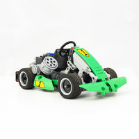
Hey there guys! I finally got myself an S-brick, i wanted to test it out so i built this go-kart. Functions: - 2 gears gearbox - auto clutch - braking system - differential The vehicle turned out to be pretty fast and with a great handling, unfortunately i need to wait some better weather to shoot a video of it and a bigger place as well. Like in a real kart there's no reverse gear so i'll probably need something like a parking lot to test it out. The gearbox is working great with the buttons of the S-brick operating the M motor I hope you'll like it!
-
[MOC] Exotik Supercar
Anto posted a topic in LEGO Technic, Mindstorms, Model Team and Scale Modeling
The name of this supercar was chose for its exotic style. The front has a particular style : there is not calander. On all the car, there are aerodynamic details, like the air intake. The rear is square. It has headlights, exhausts and air intake. The interior is quite detailed, with the dashboard. The motor is placed in the centre of the car, because of the gearbox (Nathanaël Kuipers's system). The functions of this supercar are : Steering with return to the steering wheel Full independent suspension Flat 8 fake engine with 5+R gearbox Openable front and rear hood, doors The HOG is placed in front of the dashboard. The steering wheel turns with the wheels. The suspension is quite simple, but the rear was difficult to do because of the gearbox. I have put 2 shock absorbers on both side. The gearbox is very similar with the Predator's gearbox. The idea is the same, and it is almost identical because there is not an endless of possibilities to do this type of gearbox. Here, the rear hood opening : The front hood opening is quite simple, but nice. And the most complicated function of this supercar : the doors opening. I have worked 20 hours on this function and made around 10 versions ! (~100 hours for the total) -
New 4 speed compact gearbox - easy control
Tamas Juhasz posted a topic in LEGO Technic, Mindstorms, Model Team and Scale Modeling
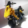
Hi! Last week I had an idea of a remote controlled gearbox, which is enough compact for vehicles and has definite control: The special part is the controller, this allows the shifting from 1 to 4 with one hand. You can shift very easily by using this positions: Neutral/start: Then 1-2-3-4 gear: This gearbox sustains high torque too, there weren't any scratches when I tested with XL motor. I was thinking about a gearbox like this since long ago, to have something with four speed to build in my mocs. You don't have to know which gear is momently engaged(like in case of steppers), just select the gear you want. It can shift from any gear to any other one, doesn't matter which is the current gear. The pictures show everything about the construction and working method. Two gearbox are combined: Of cousre, the controller motors can be placed in many other way, this is just a quick solution for working. The ratios are: first gear: 5:1 reduction second gear: 3:1 reduction third gear: 1,666: 1 reduction fourth gear: 1:1 (no reduction) --> so it's the same as the popular four speed gearbox. Folder: http://www.brickshel...ry.cgi?f=518300 This video shows the working, and the shifting times(about 4 sec from 1 to 4) can be also seen: -
.thumb.png.116032e930e483fb4ebbfdc62183bd34.png)
[Help] on Boratko's AWD transmission
Didumos69 posted a topic in LEGO Technic, Mindstorms, Model Team and Scale Modeling
Hi, In a push-along car that I'm building, I'm using Boratko's 5+R AWD gearbox and I'm running into problems when putting the gearbox into reverse. I have an AWD setup with three differentials, the center differential is part of the AWD gearbox. The front and rear differentials each drive a 20 tooth double bevel gear which in turns drives a 12 tooth double bevel gear attached to the gearbox output axle. So the overall output-wheel ratio is 28:12. I can push the car without problems in all forward gears, but when I put the gearbox into reverse, the 20 tooth double bevel gears and differentials start slipping. When I separate the gearbox from the rest of the car and drive it by hand, I can also feal much more resistance in reverse. In gears 1 to 5 everything feels very smooth. As far as I understand, the different resistance between forward gears and reverse is mainly because of the fact that in reverse 5 of the 6 gears with clutch turn against their axles and in gears 1-5 only one gear with clutch turns against its axle. Now my question is: Is this normal behaviour or am I doing something wrong? And what can I do to make the gears with clutch turn against their axles with less resistance? And a separate question: Appearantly the transfer between the differential and the 20 tooth double bevel gear is the weakest point in my drive train. They are placed in a static transfer box and in a normal arrangement with the double bevel gear placed orthogonal to the differential. Still the differential can move quite a lot. So my question is: Is there a better way to transfer drive to the differential? Hope someone can give me some directions. Thanks! Diederik -
[TC9] Rally racer
Zerobricks posted a topic in LEGO Technic, Mindstorms, Model Team and Scale Modeling
Here is my entry for the TC9 challenge A MODEL It is made out of 949 parts and it has functions including but not limted to: - All wheel drive - Independent suspension on all wheels - Working gearbox - Moving V6 piston engine - Working steering wheel - Adjustable seats - Openable doors and trunk - Detailed rollcage - Sporty colors and livery - Power Functions ready The front is full of lights and LED bars Notice the massive rear spoiler, massive exhaust system and the rear diffuusor Doors and the rear boot open, showing the internal rollcage and adjustable seats Size of the car is 35,5 studs long, 20,5 studs wide and 13,5 studs high, giving a total of 9824,626 cubic studs And the usual "money shot" of the chassis. The suspension and drive use a hybrid drive system with the drive axle used like an live axle, yet wheels suspended in a independent double wishbone configuration. And finally a digital render of the detailed rollcage: Look at it go: B MODEL Rally car rebuilds into an F1 car with following functions: - Realistic working pushrod suspension - Moving V6 piston engine driven by rear wheels - Working steering wheel - Adjustable spoiler - Openable rear to - Detailed engine bay with six exhausts The F1 car is a very low and stable model Notice the rear wheel drive, rear light, the detailed diffusor and the rear springs Rear covers can open up, exposing the pushord suspension, V6 engine and the 6 exhaust systems B model is 45 studs long, 24,5 studs wide and just 9 studs high, giving it a total volume of 9922,5 cubis studs For more details please check out the following video: -
2045 Mercedes-Benz Antos
Zerobricks posted a topic in LEGO Technic, Mindstorms, Model Team and Scale Modeling
So after a rather poor start I decided to totally reimagine and rebuild the Mercedes truck of the future. It all started with a random idea of routing 4 functions through a turntable like this: After fiddling around in LDD for few hours I came up with an 8 function gearbox powered by a single RC motor: The functions shown are: Orange - RC motor drive Lime - Horizontal extending od outriggers Yellow - Vertical extending of outriggerd Violet - Slide and tip of the bed White - Rotation of main arm superstructure Light gray- Rotation of claws Red - Lift of main arm Warm gold - Movement of claws Dark gray - Rotation of scondary arm After this rather unusual design process it was time to think of the basic shape of the model. I was inspired by the 42038 arctic truck's layout, but I wanted to add my own twist to the formula... Here's the result: Here you can see the massive cran arm used to pick up various loads: The truck uses four of the biggest Lego wheels in front and 4 tracks in the rear: As you can see all tracks and wheels have fully functional spring (and additional pendular for the tracks) suspension. Also notice the massive bed tipping angle. The truck also has a fake V8 piston engine driven by the tracks: And a prestige sand-colored interrior: Steering is done via HOG and the spare tyre behind the cab: Here's the description of the concept idea: _________________________________________________________________________________________________________________________________________________________________________________________________ This is my model for the future 2045 Mercedes-Benz competition. I named it Antos and it has several features: The engine is Euro 11 compliant 6-stroke aqua-diesel-electric hybrid. The additional 2 strokes inject water into the hot engine with expands as steam adding another work cycle. The engine also powers an electrical generator which is used to power the truck's front wheels. Front wheels also act as a generator while braking, therebye returning the electrical power back to the batteries. Tracks are driven directly by the diesel engine. For optimal performance the front is equiped with many air surfaces which reduce drag. Because this is an offroad truck, the massive wheels and 4 tracks in the rear provide it with massive traction area, which reduces ground pressure and preserves ground vegetation. The multi-functional arm and bed are driven by a single motor using a mechanical multiplexer mechanism. The Lego modes uses solid axle suspension in front, suspension on all 4 rear tracks, a fake V8 piston engine driven by rear tracks A powerfull RC motor powers the 8 functions. I managed to reute 4 functions through the turntable in order to fully motorize all arm functions. Total number of gears used for arm and bed (not including steering and fake engine gears)is over 130 making this one of my most complex switchboxes to date. The front was slightly inspired by the Unimog 400's sloped cab, but with added wings and a lower bumper. The idea for the tracks and arm actually came from the 2014 Lego technic arctic vehicle. The rear bumper is in a shape of a V in order to allow the bed to slide out and tilt. Interrior is detailed with seats, steering wheel and handles in prestige sand color. __________________________________________________________________________________________________________________________________________________________________________________________________ And as usual here's a short 3 minute video. (3 minutes is max time so you may pause some text) I hope you guys like the truck, I personaly think its a very retro-futuristic beefed up advanced half-track concept and in that sense something different and original. -

2015 Twin Assassin Supercars: P.D. Special and X19
Paul Boratko posted a topic in LEGO Technic, Mindstorms, Model Team and Scale Modeling
Since the other thread got locked, I will present these models in this new thread. I always wanted to do a Police style car so this seemed like a great opportunity to do a proper Yin & Yang take on the same vehicle... Both models feature many new 2015 parts including the new driving rings and gears in my first ever linkage style gear shifter... The black one does use some parts that are either impossible to find(19L black flexible axles) or other parts(like the 9L and 11L orange liftarms) that are very expensive... I am going to try and figure out a way to properly work around the flex axles and incorporate 16L ones, but the best presentation seems to be the 19L ones... I think with the release of the 42043 and the new white micro panels, this car can easily be done in all white, or a combination of white and another color since now the 19L flexible axles in white are abundant.. Brickshelf Folder -

Improved 3 speed automatic gearbox
darkboy101089 posted a topic in LEGO Technic, Mindstorms, Model Team and Scale Modeling
This is a remote controlled car that I am working on. This is the demo of the 3 speed automatic gearbox that I tried to improve for this project. It uses a differential gear to transfer the overload torque to select lower gear. http://www.brickshelf.com/gallery/darkboy101089/Gearbox/imag0245.jpg http://www.brickshelf.com/gallery/darkboy101089/Gearbox/imag0246.jpg http://www.brickshelf.com/gallery/darkboy101089/Gearbox/imag0247.jpg http://www.brickshelf.com/gallery/darkboy101089/Gearbox/imag0248.jpg http://www.brickshelf.com/gallery/darkboy101089/Gearbox/imag0249.jpg Current WIP http://www.brickshelf.com/gallery/darkboy101089/Gearbox/imag0251.jpg -

[MOC] Terrainroader (rally car)
MoonCZ posted a topic in LEGO Technic, Mindstorms, Model Team and Scale Modeling
Hi guys, This is my LTR (Lego Technic Rally) car, which i have build a few years ago. It has independent suspension on all wheels and it is all wheel drive. Because it is for rally i have used two RC motors for propulsion and experimental gearbox (low gear for offroad, high gear for flat roads and downhills). As you will see in video everyone use cable remote, it's because of RC motors power consumption (in that time there wasn't V2 reciever) and weight. This car no longer exist, but i still have the chassis without gearbox. Remotely controlled functions (cable): Driving (2 RC buggy motor) Steering (http://www.peeron.com/inv/parts/47154) Gearbox (M motor) Propulsion: slower RC motor output to gearbox ( 1:1, N, 12:20) and then 20:28 (differential) Steering: 12:20 to 8:steering rack Weight: about 850g Speed: (fast walk) :-D Brickshelf gallery: http://www.brickshel...ry.cgi?f=490253 Video(from the Race): Front: Back: Bottom: -

Sariel's 4 Speed Sequential RC Gearbox Using 2 Wide Driving Rings
Kiwi_Builder posted a topic in LEGO Technic, Mindstorms, Model Team and Scale Modeling
Having none of the new 3 wide driving rings is a problem if you want to build Sariel's new RC gearbox, so I decided to modify the gearbox to work with the 2 wide driving rings for all to use. I have made the LDD file which you can download below. Full credit goes to Sariel for the original design and his post can be found here: http://www.eurobrick...howtopic=107240 The green and red axles on the sides are supposed to be connected to the green and red right pieces on the model, it is like this due to LDD not allowing me to place the sides on the model. Any faults in the model, put them in comments and I'll fix them when I can Enjoy the gearbox! Sariel's 4 Speed RC Gearbox Using 2-Wide Driving Rings.lxf -
Skull Chiller, King of the Skull Army by TheOneVeyronian, on Flickr Skull Chiller, King of the Skull Army by TheOneVeyronian, on Flickr Skull Chiller, King of the Skull Army by TheOneVeyronian, on Flickr Skull Chiller, King of the Skull Army by TheOneVeyronian, on Flickr I really wanted to do my own Skull Villain (my skeleton MOC doesn't really count) complete with gearbox, so I decided to create Skull Chiller, the ultimate Skull Warrior, featuring 4 arms (which are all geared up to a gearbox so they all move when gearbox is used) and a general "armoured ice skeleton" theme. It's not really supposed to be zombified, but rather be an elegant but deadly undead warrior Be sure to click on the photos to view the large version (16 megapixels) And, in case anybody asks, that flat silver chest is a wiped Lewa Master of Jungle chest (I bought a spare one for the purpose, so don't worry I didn't mutilate my Lewa!). Positive and constructive comments are more than welcome, and I can probably provide a dissection of Skull Chiller should anybody ask for it. It's a little fragile though wth the rib bones which is why one of them appears to be missing in the last photo (it's there though)
-

[HELP] Lever Operated Gearbox
Ploki posted a topic in LEGO Technic, Mindstorms, Model Team and Scale Modeling
anyone attempted? Are there any parts aside direct control that can actually engage the clutched design gearboxes? so to actually have a stick, with either flexes or axles that would operate a transmission where engine block is. -
Welcome everybody :) Today I’d like to present my new MOC, which was built especially for a contest on LugPol. Fiat 126p Specifications Scale 1:8 Length 51s / width 23s / height 19s (41/18/15 cm) Weight: 2040 g Independent suspension Rear wheel drive RWD 4-speed sequential gearbox AAA Battery Box 88880 Functions Driving (RC) Steering (Servo) Changing gears (L) Front LED lights (switch) R2 dummy Working steering wheel Opened bonnet and trunk Opened doors with lock History I started the building of the model at the beginning of the December, to the Christmas I built chassis, later I created the body. Because of creating the Fiat, I canceled my previous project – Mercedes SLS, becuse it wouldn't fit in the rules of the competition. If you don't know, how the original car looks like, here are the pictures. Drivetrain Fiat is driven by single RC motor. The gearbox is based on Sheepo's one from Veyron. Gearbox ratio: I 5:1 II 3:1 III 1,67:1 IV 1:1 To change gears I used 1 L motor. The ratio is 8:1 (worm gear). Fiat is a bit slow, because at the beginning I didn't want to exceed 1,5 kg of weight, and I hadn't got enough time to improve gear ratio or use 2 Xls. Steering For steering I used servo motor, which propel the gear rack 1x7 with ratio 1,67:1. Suspension The front and rear suspension is independent. I tried to make the rear like the real one, what you can see in the picture. Some photos Gallery
-
Nathanaël Kuipers 2014 Supercar
Paul Boratko posted a topic in LEGO Technic, Mindstorms, Model Team and Scale Modeling
Here is an early prototype concept from Nathanaël for a new supercar... The gearbox placement is vertical behind the mid mounted engine, which is pretty unique and it works off of a slick linkage system... This will defintiely be progress to keep an eye on... More information HERE -

[MOC] MAN M1001
MajklSpajkl posted a topic in LEGO Technic, Mindstorms, Model Team and Scale Modeling
Hi, I am presenting you my latest MOC – a mega monster, which I would gladly have it parked in my backyard (I would of course need a large backyard first) - MAN M1001! Since this creation was being built during a lot of night shifts since the end of March 2013 until the end of July 2014, me and this beast are almost in a kind of relationship and through that year and a half I have hated it and loved it again, almost left it, but returned to it... Now, as this saga of mine is soon to end (recycling), I'll indulge myself a little and also write something about the real truck and some creative adventures I've had building. I also want to present the MOC with a bit more photos, I hope it is OK, I haven't found any limit regarding number of photos in a post. If there is some violation, I'll gladly make it right. Those of you, who are not so much into reading, I suggest you just skip it and proceed to photos – no hard feelings. MAN M1001 / M1002 / M1013 / M1014 I haven't found extremely much data on the web. There is a lot more on younger M1001 relatives KAT I and KAT II. A summary of the data obtained is as follows: Those trucks' production started in the early eighties in Germany in the factory MAN AG for the needs of American armed forces and have been designed as a tactical 10-ton tractor units for transport and supply of tactical missiles Pershing II (MGM-31C) and Gryphon GLCM (BGM-109G). Through several versions and successors the MAN 100x series proved to be one of the best off-road tactical vehicles around the world. According to some data, it should not have any problems with fording up to 120 cm water, climbing slopes of up to 60%, sideways driving on slopes up to 40%, overcoming the 1.9 meter trench and overcoming step to a height of 0.6 m (depending on tire size and undercarriage configurations). American forces have used four versions of the basic truck that is powered by 400 horse (several data) V10 turbo-diesel. All versions are built on extremely torsion-resistant box section framework 8x8 chassis with steered front two axles. All axles are rigid "live" axle with rubber mounted springs and large shock absorbers. Basic models are the M1001 - a tractor with a crane, winch and even 30 kW power generator and the M1002 - "tow truck" or a wrecker with a crane, a small flatbed and a carrier for a bunch of spare tires. A little younger models are the M1013 which had a crane in addition to an even bigger flatbed, and the M1014 which is plain flatbed truck. All, except the M1002, which is longer due to towing equipment, are 8.57 m long , 2.5 m wide and only 2.75 m high (cab and lift), 2.85 m (spare tire) and 3.1 m (the generator). Sources: http://olive-drab.co...tos_man_8x8.php http://man.army-uk.c...quip.php?ID=333 http://www.truckspla...odel.php?id=646 http://heavycherry.c..._tarpaulin.html At the beginning of my research and modeling, I came across information somewhere (currently I cannot find the source), that the investors (U.S. armed forces) demanded the trucks to be low enough that they can be transported by rail. It is from this demand the trucks got the recognizable cab with trimmed top edges, so the loaded trains remained in the characteristic profile of the rail. With this same purpose the engine is not mounted under the cab, but behind and partially in the cab between the two seats. MAN M-MajklSpajkl Those of you who dug a little through the source pages of the above given description of the real trucks, have probably quickly noticed, that my MOC is actually neither one of the types described - it's a hybrid. At the beginning I fell in love with the M1001, I liked it’s silhouette by far the most and began modeling , but later I found out that because my axle design, the chassis came too high and that it does not look too good as a tractor - so therefore I camouflaged the chassis with a flatbed and of course the obligatory crane. I designed the flatbed and the crane without leaning to the actual models and therefore got a little strange formation of the crane and the outriggers. I tried to replicate the crane as closely as possible though. Modeling process began by obtaining blueprints and photo-material of the M1001 and scaling it to the size of 9398 4x4 Crawler tires. Scaling to these tires produced an approximately 1:14 scale, which already shows the size – but hey, building big was the main idea! In addition to the cross-sectional blueprint of the rear I also used an "en face" photo printed out in scale, so it was much easier to model the characteristic front of the truck. You are to judge, how I pulled it off. I must say that my MAN is not nearly as technically superior as I have described its big brothers above and that it is a beast only if you use a little imagination or see it on photos… I'll soon tell you why. But first,... 1. MOC DATA: Length: 79 studs overall (63.2 cm) – I had to lengthen the chassis for 2 studs due to drive train Width: 23 studs (18.4 cm) + rearview mirrors max. 4.5 studs on each side Height: 25 studs (20 cm - top of the cab without air vents), 31 studs (24.8 cm - top of the folded crane) Weight: 3680 g (truck) + 280 g (crane) + 640 g (4 power generator (cargo) only one with six AA batteries) = 4.6 kg Part count: ALOT! I will provide exact number when I disassemble it, I'm guessing about 3000-4000 pieces - update: after painfull disassembly I counted 4404 parts. Motorized functions: - 8x8 propulsion (reduction from the engine to the wheels 1:21 in 1st gear and 1: 12.6 in 2nd) - Front two axles are steered in first/second ratio 1:0.67 + working steering wheel - Two speed gearbox (1 - 1:1667, 2 - 1:1) - Differentials lock on axles 3 and 4 - Working windshield wipers - Automatic pneumatic valve for lowering / raising the outriggers Other features and details that I would like to highlight: - Rigid full-sprung axles (live axle) - three point hitch - PF LED headlights, on/off via the PF pole reverser - Opening cab door - Adjustable rearview and side view mirrors - Manually pulled out outriggers - Separately opening sides and rear of the flatbed - "Access" to the gearbox via a door in the bottom of the flatbed - Access to the imaginary controls for pneumatic or. "Hydraulic" pump through the side door on the flatbed - Access to power switch for the front light through the side door on the flatbed - Spare tire - Illustration of the engine behind the cab - Manually "driven" crane Atlas 4300 M5 with a double pull-out arm and winch - "Rich" dashboard - Seats and shifting stick in the cab - Protective grids for front and rear - Cargo – power generators (the idea was born out of a major sleet storm in our country past winter) - I must have forgotten something... PF components used: - 2 x XL motor for propulsion (engine coupled with the so-called "adder" differential) - 1 x L motor for steering - 4 x M motors (auto-valve, gearbox, differentials lock, wipers) - 2 x PF switch (on / off lights, pole reverser on one of the XL motors) - 1 x PF led lights in front - 3 x IR receiver (v2 drive and wipers, 2x the ordinary for the rest) - 4 x large BB (one for power, three for lipstick – power generators) - 1 x IR Speed Remote control (drive and wipers) - 2 x IR remote control (the rest of the motorized functions) - 1 x PF extension wire 20 cm - 2 x PF extension wire 50 cm And now some photos to take a breath during such a heavy reading… Looking mean… Ready to unload… The crane stood relatively well to the loads applied, due to much bending I have only tried it with the empty generators. High loads (kids) led to the main two LA snapping of the pins, since they were not transversally braced. Atlas 4300 M5 crane Flatbed with lowered and removed sides… The generators… I find them quite cute, so the lineup was necessary. For those who have yet to read themselves out of breath, I would have a little description of the "guts" of this birdie. Bare naked chassis (more or less) for starters: 2. CHASSIS AND BODY The truck was meant to be modeled as realistically as possible and so I decided for the chassis of two main studfull beams, which were laterally connected in a fairly robust box-section frame by the 5x7 technic frames. The beams were changed countless times, because in the course of construction a need for holes exactly where they were not would came up, or there were certain parts in the way, etc. The cabin is built from a combination of studfull and studless technic bricks, and even some sytem bricks were used for better looks. All other parts of the truck are in "full studless" technique, with some little system bricks add-ons. 3. AXLES and DIFFERENCIALS LOCKS As soon as I had the idea for a 8x8 truck, along came the idea of planetary reduction within wheels. There are very good solutions for this kind of reduction within the "large racing" wheels (ZBLJ), for "medium racing" I found none, well at least not such that would ensure that the technic turntable is as close to the wheel as possible. I thought of a solution shown below, which looks good, but has the disadvantage that it is necessary to attach the wheel to the turntable before attaching the turntable to the axle. The wheel is attached to the freely rotating 4L axle with stop, so it must be pushed next to the turntable well and in such a way that small technic bush and the free end of 2L red axle are caught between two spokes of the wheel. Of course, the wheel must be turned with the spokes inside. It was a little easier to push the wheel into place when I got some new axles 5L with stop... I find this kind of reduction very interesting, but it creates a lot of friction, which is fatal as you'll read further on. The trucks' axles were the first parts designed and they too, like the chassis, have seen many, to many variations. Back then, when I was designing the axles, I only had enough of the "new" bewel differentials. Locking those is a little more volume-consuming, and therefore such a fat boy for the axis, which you can see below. Differential is actually locked by locking a "by-pass" axis. Because I undertook this for the first time and because I spent all 9L links I had on suspension, it was a real hassle to find a solution for remote locking differentials. I figured out some kind of lever solution, where the mechanism mounted on the chassis practically just hugs a small lever on the individual truck axle. In such way both of the non-steered axles' differentials are synchronously locked. Unfortunately, the system worked well for the locking, while the unlocking of the rear axle was very hard or almost never unlocked -I blame the designer! On the photo below, you can see the transmission from the motor to the double "fork" from the bottom side of the truck and the »fork« hugging the lever in the detail in the lower right corner of the photo. 4. PROPULSION This is more or less a sad story - maybe mix of bad decisions and inexperience. Yeah, THAT THING WON'T DRIVE! As you will see in the video I’m preparing, it only works in the "air" mode. The reason? This colossus is heavy as ... and my enlightenment has insisted on feeding drive to all four axles from a single source. Imagine now half a meter long technic spindle full of universal joints and to ensure easy win, use two CV joints directly on the power source. Those babies sure can take some torque - NOT! Add another bunch of gear in each axis and in each wheel and you get a CV joint without the »joint« part. Anyway ... noted, written in the black books of things not to do! After many attempts, I decided to leave the matter as it will; it should be as an example for the future. 5. STEERING Again, things could not be much worse here, well I suppose it could fall apart completely. However, I like the concept that I tried to put to work very much, so it was again left to be represented in the "air" variant: Proposed design does not use the usual steering rack, but a system of levers, a bit closer to the real 4 axle truck steering system. One wheel hub is pushed forward and backward and this hub is linked to its own pair to the other side of the axis by a rod. The theory is, of course, one thing, and the reality is another. Please find below a display of described system, first the mechanism on the left side of the chassis where the motor is. The worm screws drive two lateral axles and steering wheel in the cab for which I've succeeded quite an interesting transfer with simultaneous reduction 1:8 of L motor speed (see the detail). Each of the transverse axis has a different reduction of rotation, so as to ensure a smaller turning of axis no.2 against axis no.1. Thus, the reduced rotation drives the levers, which steer the wheels. For this reduction, there is quite a simple calculation using geometry - for my MAN it should be 1:0,73. I spent some time looking for the most ideal relationship between the technic gears, but then again, a compromise, and I installed the ratio of 67% (1 - 12/24; 2 - 12/36), which is not very far off. The system, unfortunately, did not work under the weight of the cab and there was too much backlash in all these levers. In order to alleviate the matter, I connected the levers with technic friction pins, hence the axis are a bit jumpy when "air" steering due to overcoming the friction in pins. I know, I should change back to frictionless pins for »air« steering presentation, but… hmnjah… 6. WINDSHIELD WIPERS Motorized windshield wipers are one of the cutest and reliable functions of this little toddler, especially since they're controlled via the IR Speed remote control and thus can adapt to the amount of rain. It is a simple version of the system that drives wheels on steam locomotives - the rotation transferred to the oscillation. It only bothers me, that I somehow didn't manage to get the motor that drives the wipers somewhere in the bottom of the cabin and therefore there is a driving axle between the seats leading to the motor behind the cab, which is to me quite a fine mockup for the real engine. The reason that there is no room under the cab is in the fact that the main beams of the chassis stretch quite deep into the cab and that the suspension of the front axle is attached just below the seats. 7. AUTOMATIC PNEUMATIC VALVE and CRANE OUTRIGGERS When I was almost finished with the truck, there was only one free PF function left and the crane outriggers were missing. There was practically no space left, except behind the spare tire. Luckily, I managed to squeeze in there a modified version of the automatic pneumatic valve by My version is just geometrical adaptation to the space that was available and I think I succeeded well. For those who may not know (not many here I guess): automatic pneumatic valve (there is quite a handful of different types from several inventive authors on the web btw.) is a pneumatic valve with only one motor powering a pneumatic pump and switching the lever of the pneumatic valve at the same time. I had quite some difficulties and I spent some time looking for the right combination to attach the valve softly enough to work as it should. If it was too stiff, it would not change the valves position when changing the motors direction. From left to right you can see a pneumatic pump, driving PF M motor and worm with a pneumatic valve on the photo below. The solution for the outriggers manual extension is IMHO really a small piece of art. Well, a good idea at least. They’re mounted in 5x7 technic frames, through which two axles slide and are protected from falling out by a connector. Since the pneumatic tubes pushed the outriggers outside, I made a "lock" to hold them in place. Loading capacity of the outriggers is of course purely symbolic. CLOSURE, FINALLY And now to conclusion: I'm tired, and not of writing so much of my bad English. I will not start on such a vast (at least to me) and long lasting project for some time, if ever again. I'm really happy that I can finally fully present this MOC to you and I am pleased also that I insisted until it was finished, even though not completely succeeded, but managed to learn a lot of new in terms of design and construction of such a model. I am pleased with the level of small details, which I think for me is increasingly important for a MOC to have. Thanks to all who survived this long writing, as well as the rest of you who just looked at photos and grimacing at the amount of the text. No hard feelings, eh? For those curious, find at this link a number of additional photos, including some of those during the construction, which I didn’t include in the presentation. Best regards, here is another photo of my third child to conclude. Miha And finally - a video: -
Volkswagen Beetle (Type 1)
Sheepo posted a topic in LEGO Technic, Mindstorms, Model Team and Scale Modeling
Here is my lastest car. The classic Volkswagen Beetle, officialy called Type 1, or informally in some places around the world the VW Bug. This car received a lot of modifcations and improvements along the years, I have built the 1967 model. This car is made in scale 1:7.8. The total size is: 65 studs of length, only 25 wide and 23 of high (50x20x18 cm) The weight is 2.5 kgs, with around 3000 parts and 5 motors. As always it includes some remote controlled functions: - Steering (M motor) - Drive (2 XL motors) - Sequential gearbox (PF Servo motor) - Brakes (M motor) The sequential gearbox is a modified version of the Mustang's gearbox (3rd Gen V2), with 4+N+R speeds and as always with auto-clutch. The speeds ratio: R - 1.25:1 1 - 1.25:1 2 - 1:1 3 - 1:1.33 4 - 1:1.67 The max speed in 4th speed is 4 kph (~2.5 mph) It has a gear indicator in the interior, between the front seats. Boxer-4 fake engine under the rear bonnet. The bodywork Also you can disassembly the bodywork removing only 5 pins, do it is very easy and fast. A complete bodywork with openable doors, front trunk bonnet and and rear engine door. Also the doors have lock, you need turn the door handle to open it. It has 4 full size seats and folding front seats. The suspension is based in the real one: front rigid beam independent suspension axle and rear swing axle. Also the front axle has stabilizer bar. The steering has ackerman geometry and working steering wheel. The car also has working brakes in all wheels: disc brakes in the fron and drum brakes in the rear. In addition it includes functional brake pedal. Now the "most wanted" picture for technic fans. Like the Mustang the instructions will be available coming soon Finally as always a little video: As always for more info visit my website: sheepo.es -
[WIP] Suzuki Samurai
piterx posted a topic in LEGO Technic, Mindstorms, Model Team and Scale Modeling
Hello everyone! yeah i know, i have to finish the stratos first ....the thing is that on 15th of august, all the italians go to have a picnic in the wild, so as i'm going to the mountain i NEED to have a 4x4 to bring with me :D So after Vitara it's time for Samurai, and this time it's gonna be huge and possibly dark blue! My goal is to have these features: 4x4 lockable center and rear differentials high-low ratio gearbox winch dark blue color fabric white soft top lights if i can, i'd like to make a mechanism to operate the following sequence high ratio -> low ratio -> diff lock -> winch so the car could handle every situation (hope you got what i mean XD) for now i only built the front axle :) i hope you'll like this project! -

Linear Actuator Gearbox
anton1678 posted a topic in LEGO Technic, Mindstorms, Model Team and Scale Modeling
I was looking at TheItalianBrick's post about the modular gearbox, and I tried to make it. This is too big for that topic, so I made this my own topic. I failed, so I tried my own way. It uses a linear actuator to make a really thin, long gearbox, though I could make it normal with just one tiny gear. It allows smooth movement back and forth, for each of the 4 functions. I wouldn't recommend this in a short vehicle, because it widens and shortens, best used in like a crane or something. It uses 1 motor for drive, 1 for change, and has 4 functions. You could use just one of these gearboxes to power 2 more, and those to power 4 more, then 8 more, then etc. You'd need a lot of torque, but it could work, eventually to 64, 128, 256 even, functions for just 2 motors, if you have enough bricks. I could build about 2 more, so 8 functions for me. -
Techlug 23rd contest - Telescopic handler
PG52 posted a topic in LEGO Technic, Mindstorms, Model Team and Scale Modeling
Hi everyone ! I'd like to present to you a new creation for the 23rd Techlug contest, it's a telehandler. It has 4 wheel steering with HOG and a working steering wheel, and a gearbox (Erik Leppen's system : http://www.techlug.f...topic1099.html) with 4 features : - Stabs - Boom lifting - Boom extending - Fork (or bucket) tilting The goal : to make a fully functional and easily playable telehandler, which can be motorized adding the lego technic 8293 power functions pack. Here is the video (in french with subtitles) : Pictures : LDD file : https://www.dropbox....telehandler.lxf Hope you like it, and if you have questions, just ask, I'll be happy to answer ! -
.thumb.jpg.2335d10c31c9ffa7029728589340e12f.jpg)
Gears, most wanted
efferman posted a topic in LEGO Technic, Mindstorms, Model Team and Scale Modeling
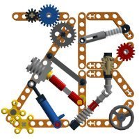
because myself is actually in sickness to make some gears, which one would you like to have or, for purists, only to see? planetary gears, torsen diffs or worms which can fit on 12 and 20 tooth gears? anything else interesting in your mind? -
Ford Mustang Shelby GT500
Sheepo posted a topic in LEGO Technic, Mindstorms, Model Team and Scale Modeling
This is the car I showed in the Lego Fan Weekend two weeks ago. This creation is made in scale 1:8. The total size is: 75 studs of length, 29 wide and 21 of high (60x23x17 cm) The weight is 3.1 kgs, with around 3500 parts and 5 motors. It includes some remote controlled functions: - Steering (M motor) - Drive (2 L motors) - Sequential gearbox (PF Servo motor) - Disc brakes (M motor) The sequential gearbox is an improved version of my previous Caterham ones (3rd Gen V2), with 5+R and auto-clutch. The speeds ratio: R - 2.08:1 1 - 1.67:1 2 - 1.25:1 3 - 1:1 4 - 1:1.33 5 - 1:1.67 The max speed in 5th speed is 3 kph (~2 mph) It has a gear indicator in the interior, between the front seats. For make more easy the gearbox tests the car in has a rear support to keep the rear axle lifted The suspension is based in the real one: front McPherson axle and a rear 4-links live axle. The front axle also has advenced geometry: Camber angle(2º), caster angle(3.5º) and kingpin angle(7º) The steering has ackerman geometry and working steering wheel. The car also has working disc brakes in all wheels, they are very powerfull and includes functional brake pedal. The complete video COMPLETE INSTRUCTIONS WILL BE AVAILABLE COMING SOON!! As always for more info visit my website: sheepo.es -
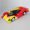
This is my smallest "supercar". It features a 5 speed diagonal gearbox which is very low and perfect for such a small model. The model also has independent suspension on all wheels steering in the cab and the rear, working V8 engine and suicidal doors and foldable roof. I got the wheels from my friend Mahjqa when I was travelling arround Europe and they fit very nicely to the 68Z tyres. The wheels are much deeper than usual Lego wheels and allowed me to make very small independent suspension system. Using brick built hubs allows the front wheels to steer some 45 degrees, making this car really maneuverable. The styling is 2000's erm...style with chromed wheels, metallic colors, transparent engine blocks and flexible tubing. The two gears in the back are for steering and raising the roof. The gearbox works suprisingly good, its very low, compact, smooth but unsychronized, which I think in this small non-motorized model is not a big problem. I also made and LDD model, but due to the new update bug is missing the springs, there are also not correct wheels and there were some problems putting the seats all the way inside the model. DOWNLOAD LXF HERE: http://www.brickshel...bug/junebug.lxf And a small video:
-
Mitsubishi Pajero Pinin
piterx posted a topic in LEGO Technic, Mindstorms, Model Team and Scale Modeling
Hey guys! Some of you have already seen the WIP thread, so here's the video and proper pictures of my latest moc! Mitsubishi Pajero Pinin This is the car I own in real life so i always thought about building it out of legos :D It's been quite a long way to get it complete but I finally made it! Features: - 4x4 - 4+N+R sequential gearbox - Auto clutch - Braking system - Mac pherson strut - Rear live axle - Brake lights - Front lights - Openable doors, hood and bonnet - Working steering wheel Here's a video of it The model works good except for the 4th gear wich is hard to engage as the gearbox is un-synchronized...on the other side the braking system works great! I actually didn't expected it to be so powerful, it can stop the model in a small space even if it's travelling fast. I hope you'll like it :) -

[MOC] [WIP] Old Skool Rat Rod
EvilEnderman posted a topic in LEGO Technic, Mindstorms, Model Team and Scale Modeling
Ello all, been a while since I've posted an MOC here. Over this weekend, I've been working on a studfull build (haven't built like this for a long time) My aim was to make a small-mid scale rod, with realistic functions. It contains: 4 speed gearbox v6 fake engine Cowl steering (HOG) Not to mention the 'gothic' shredded interior. However, before I start the main bodywork, it's just that when I look at it so far, it doesn't seem right... http://imgur.com/a/fCTuH Edit: @Jim - Thank you for the tip - I have resized them all to a max width of 1000, which should be fine! What do you guys think? - What's that thing that isn't right, or anything to improve? (Will post progress here too) - I will be finishing the build definitely! Thanks! - Enderman -

Gearboxes and clutch gears and bracing (oh my!)
Captainowie posted a topic in LEGO Technic, Mindstorms, Model Team and Scale Modeling
I just had a "Eureka" moment. I have recently been spending a fair bit of time re-designing the power transmissions for some of my GBC modules. I made sure that everything was properly braced, all the axles were supported in at least two places, etc. I also took the opportunity to include one of the torque-limiting clutch gears, in case something goes wrong and the mechanism binds. My realisation was that if I'm going to put in the clutch gear, I don't need to go overboard re-inforcing the structure - I only need it to be strong enough to withstand the amount of torque that the clutch gear can provide, rather than being able to withstand the torque of the driving motor. The clutch gear will slip before the bricks come apart. I guess my point is that bracing and structural soundness is all well and good, but it is certainly possible to make it far sturdier than you need. Owen.