Search the Community
Showing results for tags 'sequential'.
Found 21 results
-
.thumb.png.116032e930e483fb4ebbfdc62183bd34.png)
Understanding LEGO 4-speed sequential gearboxes
Didumos69 posted a topic in LEGO Technic, Mindstorms, Model Team and Scale Modeling
I finally took the time to write down the things I have come to understand with regard to LEGO 4-speed sequential gearboxes. I am receiving many questions about gearboxes and I hope these understandings can help you reason about a gearbox layout while you're building one or trying to design one. I hope this also answers a question I received from @nerdsforprez more than a year ago, which I did not answer yet. Gearbox layout Let's take a look at this 4-speed sequential gearbox layout. Black is input, red is output and orange is control. The main input is divided over a high input (black) with high input ratio and a low input (white) with low input ratio. The high input ratio is 1:1 (via a 12:12 mash) and the low input ratio is 1:2 (via a 8:16 mash). This makes for a combined ratio of (1:1) : (1:2) = 2:1 between the high and low inputs. I will refer to this ratio as the primary ratio. In fact this ratio is the ratio between the two driving rings. Both driving rings have a high output (green) with high output ratio and a low output (yellow) with low output ratio. For both driving rings, the high output ratio is 1:1 * 2:1 = 2:1 (via a 16:16 mash and a 16:8 mash) and the low output ratio is 5:3 * 1:2 = 5:6 (via a 20:12 mash and a 8:16 mash). This makes for a combined ratio of (2:1) : (5:6) = 12:5 between the high and low outputs of each driving ring. I will refer to these ratios as the secondary ratios. Rotary catch and quadrants Even though I will explain things in terms of the gearbox layout described above, the first understanding I want to address, applies to practically all 4-speed sequential gearboxes with 2 driving rings. Let's take a look at the rotary catch and driving rings from above and divide the layout into four quadrants. Each quadrant represents one of the four gears of the 4-speed gearbox. When we turn the rotary catch clockwise (seen from the left) with 90-degree steps, it will always make the following path through the four quadrants. From the path the rotary catch draws, we can see that it toggles from one driving ring to the other driving ring for every 90-degree step. So if we want to obtain a useful gear sequence (either a 1-2-3-4 sequence or a 4-3-2-1 sequence) along that path, we need to tie gears 1 and 3 to one driving ring and gears 2 and 4 to the other driving ring. Otherwise the rotary catch can never 'toggle' between subsequent gears. Now let's take a look at all distributions of the four gears over the four quadrants that meet this requirement. Starting top-left, this will produce a 1-4-3-2 sequence. Repeating the sequence will give 1-4-3-2-1-4-3-2-etc., which effectively boils down to a 4-3-2-1 sequence. Starting top-left, this will produce a 1-2-3-4 sequence. Starting top-left, this will produce a 3-4-1-2 sequence. Repeating the sequence will give 3-4-1-2-3-4-1-2-etc., which effectively boils down to a 1-2-3-4 sequence. Starting top-left, this will produce a 3-2-1-4 sequence. Repeating the sequence will give 3-2-1-4-3-2-1-4-etc., which effectively boils down to a 4-3-2-1 sequence. Starting top-left, this will produce a 2-3-4-1 sequence. Repeating the sequence will give 2-3-4-1-2-3-4-1-etc., which effectively boils down to a 1-2-3-4 sequence. Starting top-left, this will produce a 2-1-4-3 sequence. Repeating the sequence will give 2-1-4-3-2-1-4-3-etc., which effectively boils down to a 4-3-2-1 sequence. Starting top-left, this will produce a 4-3-2-1 sequence. Starting top-left, this will produce a 4-1-2-3 sequence. Repeating the sequence will give 4-1-2-3-4-1-2-3-etc., which effectively boils down to a 1-2-3-4 sequence. Surprisingly, every distribution that meets the requirement, will produce either a 1-2-3-4 sequence or a 4-3-2-1 sequence. What this tells us, is that it's enough to tie gears 1 and 3 to one driving ring and gears 2 and 4 to the other driving ring, to obtain a useful gear sequence. Nothing else matters! Primary ratio vs. secondary ratios The next understanding I want to address, concerns the relation between the primary ratio (the ratio between the high and low input) and the secondary ratios (the ratios between the high and low outputs of both driving rings). We have already seen that in the gearbox layout at hand, the high and low output ratios are the same for both driving rings. One thing we can say about 4-speed gearboxes in general, is that the ratios between gears 1 and 3 and between gears 2 and 4 need to make a bigger difference than the ratios between gear 1 and 2 and between 3 and 4. Now when we take into account that gears 1 and 3 need to be tied to one driving ring and gears 2 and 4 need to be tied to the other driving ring, and we use the same high and low output ratios for both driving rings, we can say that the secondary ratios, which constitute the ratios between gears 1 and 3 and between gears 2 and 4, need to be bigger than the primary ratio, which constitutes the ratios between gears 1 and 2 and between gears 3 and 4. The gearbox discussed in the beginning of this post has a primary ratio of 2:1 and secondary ratios of 12:5, so it meets the above requirement. Check! Swapping and reversing If we go back to the distributions we listed above, we can see that half of them generate a 1-2-3-4 sequence and half of them generate a 4-3-2-1 sequence. When we study them more thoroughly, we can see that all 1-2-3-4 distributions have a horizontally flipped counterpart with a 4-3-2-1 sequence. In other words, if we flip the distribution horizontally, we reverse the gear sequence. Example: Swapping 1-3 with 2-4 in a 4-3-2-1 sequence produces a 3-4-1-2 sequence. Repeating the sequence will give 3-4-1-2-3-4-1-2-etc., which effectively boils down to 1-2-3-4. Example: Swapping 1-3 with 4-2 in a 1-2-3-4 sequence produces a 4-3-2-1 sequence. What this tells us, is that when we mirror the gearbox layout left-to-right (top-down in the quadrants), which boils down to swapping the high and low inputs, the effect is that we reverse the gear sequence. Practical value: If you find yourself in a situation where you want to swap the upshifting and downshifting directions, simply swap the high and low inputs, like in the image above. Finally, if we take one more look at the gear distributions above, we can see that when we swap gears 1 and 3 or gears 2 and 4 in any distribution, we get a distribution with the reversed order. 1-2-3-4 will produce 4-3-2-1 and 4-3-2-1 will produce 1-2-3-4. When we swap both gears 1 and 3, and gears 2 and 4, we reverse the order twice and get again the same order. Example: Swapping 1 and 3 in a 1-2-3-4 sequence produces a 3-2-1-4 sequence. Repeating the sequence will produce 3-2-1-4-3-2-1-4, which effectively boils down to a 4-3-2-1 sequence. Example: Swapping 2 and 4 in a 1-2-3-4 sequence produces a 1-4-3-2 sequence. Repeating the sequence will produce 1-4-3-2-1-4-3-2, which effectively boils down to a 4-3-2-1 sequence. Example: Swapping 1 and 3, and 2 and 4 in a 1-2-3-4 sequence produces a 3-4-1-2 sequence. Repeating the sequence produces 3-4-1-2-3-4-1-2, which effectively boils down to a 1-2-3-4 sequence. What this tells us, is that when we mirror one side of the gearbox front-to-back (swap the high and low outputs of one driving ring), we will reverse the gear sequence. When we mirror both sides front-to-back (swap the high and low outputs of both driving rings), we won't affect the gear sequence. Practical value: If it's more convenient for the rest of your build to mirror your gearbox layout front-to-back, like in the image above, you can do so without any consequences. If it's more convenient to mirror only the left side or the right side of your gearbox layout, you need to also swap the upshifting and downshifting directions. If you want to inspect the gearbox used in this post in 3D, here it is in Stud.io format and here in LDD format. -
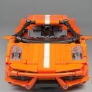
[MOC] Rugged supercar - Hammerhead (1:9 scale) - Revisiting
Didumos69 posted a topic in LEGO Technic, Mindstorms, Model Team and Scale Modeling
Rugged supercar - Hammerhead (1:9 scale) This project was not something I started very consciously. Also for me it evolved into something special. I was especially happy with the interference (in a positive way) of other builders. A big thank you to this community, for pushing me in the right direction on several occasions! The most special part - to me - of this build, is the chassis. It combines a simple 4-speed AWD transmission, a flawless sequential shifting mechanism and advanced suspension setups with Ackermann steering, anti-roll bars, torsion bars, 2 studs ground clearance and 2 studs suspension travel. All wrapped together in a very flat yet rigid and coherent structure with a mid-console width of only 5 studs. I did not want the bodywork to make any compromises to these features. I wanted the body to continue the line of durability set in by the chassis. Flex-axles do not fit that image, hence no wheel arcs. They would also sit 2 studs above the hood - not very elegant. The result is a car that does not only look fool-proof; it is fool-proof. After a rough treatment, you don't need to tighten connections or fine-tune gears to avoid friction. You can carry the car by the sides, by the trunk door (rear wing), by the nose and by the bumpers without displacing any parts. You can even grab the 2Kg build by the roof and turn it upside down to see the bottom side without a problem. So I did not intend to level with great bodywork builders. To me the biggest compliment is that some have referred to this model as the successor of 8865 and 8880. Drive train AWD with 3 differentials Sequential 4-speed gearbox One-finger shifter V8 fake engine Suspension Double wishbone suspension Anti-roll bars (front & rear) 2 studs suspension travel 2 studs ground clearance Steering Ackermann steering Gear-rack sliders Working steering wheel HoG steering Chassis Sturdy and durable Integrated bumpers Adjustable seats Narrow mid-console (5L) Bodywork Sturdy and durable Integrated roll-cage Lockable doors Openable trunk Liftable By the roof By the sides By the nose By the trunk door Instructions are available on Rebrickable. There is a full-featured version called 'Rugged supercar' and a chassis-only version called 'Flat AWD chassis'. The chassis-only version confines itself to part 1 of the instructions of the full-featured version. Special thanks to @Blakbird and @BusterHaus - with Blakbird being the driving force - for taking on the task of making these beautiful instructions! Making instructions for a build like this is a tremendous amount of work. Even more so, given the fact that I have been very demanding in sticking to my original design. - 32005a (Link 1 x 6 without Stoppers) - used for the anti-roll bars and steering tie rods - is preferred over 32005b (Link 1 x 6 with Stoppers), because each link has tow-balls inserted from both sides. 32005b can be used too, but in that case each link will have one tow-ball that needs quite some force to insert. - 32056 (Liftarm 3 x 3 L-Shape Thin) - used for the door locks - is preferred over 32249 (Liftarm 3 x 3 L-Shape with Quarter Ellipse Thin). 32249 can be used too, but makes it more likely to accidentally lock the door while it's open, which is not a big deal of course. - 76138 (Shock Absorber 6.5L with Soft Spring) - used for the door locks - should be soft springs. They are quite rare in red, but you could also use two LBG soft springs. - 85543 (Rubber Belt Small (Round Cross Section) - used for the 90 degree limiter and the return-to-center of the gear shifter - should be relatively new, say max 2 years. Not that they wear out quickly, but the older ones are slightly less tight. Images of the full-featured version can be found here. Images of the chassis-only version can be found here. See the entry on The LEGO Car Blog! P.S. Where real cars start with a sketch, evolve into a professional design and finally have their technical details filled-in, this project started with some technical details, evolved into a complete design and ended up in a sketch ;-). By @HorcikDesigns (http://horcikdesigns.deviantart.com/gallery/). -

Ultra Compact 8+N+R Sequential Gearbox
Anto posted a topic in LEGO Technic, Mindstorms, Model Team and Scale Modeling
This gearbox is an upgrade of my ultra compact 8-speed sequential gearbox. The 8-speed gearbox was nice but it was frustrating to know that the 2-speed gearbox took as much space as the 4-speed gearbox. I thought about transforming the 2-speed gearbox into a 2+N+R one. I had an idea about how to transform this gearbox but I didn't really think about how to activate the reverse and the neutral. Maybe by doing something with the knobs... I spoke with @Charbel and he gave me the idea to use the Bionicle parts I already used on my previous gearbox. Then I ended up with this: I used large frames as in the Lamborghini Sian. They make the whole gearbox stiff and now you have just to build a chassis arount the 'box! The neutral was extremely simple to do. See by yourselves: The reverse was more complex to create. For every foreward speed, the 2+N+R-speed gearbox rotates the 4-speed gearbox by the red 16t at the bottom. The reverse doesn't use the 4-speed gearbox, it uses the blue 20t at the top of the picture below: To engage the neutral and the reverse, I fixed two Bionible parts on the left knob. So they act as a smaller knob, with two teeth, and at a point 1/4 turn of the right knob makes the left knob rotate by 1/4 turn, whereas for all the foreward speeds, the left knob does 1/4 turn every turn of the right knob. Reverse engaged: Neutral: First: There is a stop not to shift from the 8th to the reverse. The engine and the gearbox wouldn't appreciate. The wheels have to be connected the the red axle and the engine to the grey one. It's possible to use this gearbox for a 4WD vehicle easily since the red axle goes through the gearbox. With this gearbox you don't have to use a 8-speed gearbox and a DNR one anymore, as in the Chiron or the Sian. It saves space, and you can't engage the 4th speed whereas you are in neutral - all the speeds shift into a logic order. I will make instructions when I have time! -
7+R sequential gearbox (DCT)
Leviathan posted a topic in LEGO Technic, Mindstorms, Model Team and Scale Modeling
Hi everyone, Lately, I read topic on Audi R8 from Jeroen Ottens (https://www.eurobricks.com/forum/index.php?/forums/topic/178368-wip-audi-r8/) and it remembers me that I had such a prototype of a sequential gearbox. It's an improved version of my sequential gearbox used on my Bugatti Chiron 1/8, lighter and more compact. I use 4 orange rotary changeover selectors. I just want to say that is only a prototype version unfinished that I wanted to share with you. Please do not judge assembly design, but system core. How does it works ? - The main shat is the center one and it's made the dual clutch shaft - On each side, there is 1 half-gearbox. One with odds speeds (1, 3, 5, 7) and the other one with even speeds (R, 2, 4, 6). - On main main shaft, there is an offset of 90° between the 2 orange changeover. Its engage only at time one of the half gearbox. The real secret of the gearbox is the offset between each half gearbox. I used a factory wheel with 2 pins with tow ball to create this offset. See the picture below : Of course, the gearbox has a end stop to prevents 7 to Reverse shifting. Ratios ; R : 1,2 1 : 0,6 2 : 0,75 3 : 1 4 : 1,67 5 : 1,8 6 : 2,1 7 : 3 The reverse speed is too fast. I worked to an improved version too, smaller that prototype. The arrow shows the right way to shift up. Finally the video to understand the mecanism : I hope you will like it ! See you soon ! -
Hello everybody! This is the first MOC I present on Eurobricks. My most popular MOC yet is the 3 speed auto gearbox (https://rebrickable.com/mocs/MOC-33711/lbrix/3-speed-auto-gearbox-overworked-version/?inventory=1#comments). But now to this gearbox: At first ask yourself this question: Which sense has a normal D-N-R gearbox in a manual technic car? It has no sense. It makes no difference if you are in the forward gear or in te reserve. But with this D-N-R gearbox it makes a difference, because if you are in the forward gear, you can not push the car backward and if you switch in the reserve gear, you can not push the car forward. If you want to build this gearbox into a technic car, you have to connect the grey connectors to the wheels and one of the black ones to the fake engine. For more information check out this MOC on rebrickable (maybe it is not approved yet): https://rebrickable.com/mocs/MOC-47985/lbrix/alternative-d-n-r-gearbox/?inventory=1#comments No I wanted to ask you, what you think about this D-N-R gearbox? Here is an video of my gearbox:
-
Hi all, Here is my next project. First i would like to say that this is shot as a really early design stage. This is the first rush on that project. I do command from TLG the new orange selector for gearboxes. I do not received them actually. My first impression when seeing them for first time was that they were designed and intended to fit into a bike gearbox. That it was their reason of existing. And, as you always have better following your very first inspiration I do began the work on this project. Pictures! First, the main frame. As it do exist multiple sorts of frame I choose one who is the less conventional in a sense for a Lego model: This frame offer many advantages on a scale model, the main one is to free a maximum of space for the mechanics. Other view: The challenges are quiet hard on this project. As for many small MOCs the smaller they are, the most compact mechanics has to be and hardest is the designer's job. I am not a designer and even not engineer so i'll try do do my best to reach my goals with the best result I can. Here are my (hopefully) goals: - Superbike inspired - 4 speeds gearbox, with, if possible but I do not figure out on how, a neutral point correctly positioned between first and second speed. - Shifter commands like the real machines ... On design point of view, those bike are often fully careened . I do not think this will be the best choice for a technic model, as it would be great to have a full look at mecha inside. Here are the very first rushes on design: As you can see on the pictures below, there are still so much work to do.... For those who follow my workflow, you will understand my working method. I will now rebuild a second model independently of this one. I think I must begin by the engine part included gearbox setting and stepper commands. If you have any opinion idea or experience on this subject, feel free to post your stuffs and inspiration. Good sunny day all !
-
Ultra Compact 8 Speed Sequential Gearbox
Anto posted a topic in LEGO Technic, Mindstorms, Model Team and Scale Modeling
I made it almost a year ago, but I didn't have the time to make its presentation. It's a gearbox I made at the release of the rotary changeover catches. My purpose was to make a gearbox as compact as possible. So I decided to couple a 2 speed gearbox to a 4 speed gearbox. There are 2 advantages: firstly the gearing is more compact, and then the shift system is also pretty compact. When the changeover catch of the 4 speed gearbox makes one turn, it activates the one of the 2 speed gearbox. So to change the speeds from the lowest ratio to the highest, the 4 speed gearbox does 1; 2; 3; 4 while the 2 speed gearbox is in first gear; then the 4 speed gearbox activates the second speed of the 2 speed gearbox, and it does 1; 2; 3; 4 again. Little trick: when you make a double gearbox like this, it's important to be sure that the gears are in the right order. This means the 6th gear (2-2) must not to be lower than the 4th gear -1-4) or you cannot control the gearbox properly. So in Excel, I recreated the structure of the gearbox using cases in the calculations (for example F3*G3/F4*G4). Then I put the number of teeth of the gears I may use in the cases, and I got the final ratios of the gearbox. After some tries, I got a good result, and a perfectly controllable gearbox. To control this gearbox, I used the stepper of the Bugatti Chiron that I compacted a little bit (the piece in red). To finish, a modelization of the mechanic to have a clearer view of the gears: Finally, this is an extremly compact gearbox, easily controllable. -
[POC][WIP] Compact 90° stepper w/ instructions
Didumos69 posted a topic in LEGO Technic, Mindstorms, Model Team and Scale Modeling
After shortening the travel required to shift gears in my improved paddle shifter unit for the Porsche (42056), I put some effort in trying to use the same concept - a lever knob gear driving a central knob gear - as a base for a 90 degree stepper. I was able to make a compact setup with the shift lever directly operating the shift axle that could in turn drive the clutches of a gearbox (the gearbox is not part of this unit). By using the knob gear inside the shift lever, the rotation speed of the central knob gear is twice the rotation speed of the shift lever itself. As a result each shift requires only a relatively short travel. The stoppers that catch the upper knob gear when shifting are the crucial part of this mechanism. They had to be reliable when it comes to catching the knob gear and needed to allow for a smooth return at the sane time. The whole setup relies on its interaction with the simple 90° limiter., which has been integrated in this unit. I'm very happy with the result. EDIT: I've been working on this a little more. I'wasn't completely satisfied about the return of the shift lever. It requires a lot of silicon power and I couldn't get it working with a new set of red silicon bands. Apparently the old ones (+/- 8 years old) are stronger. So I decided to skip the auto-return completely. The return is not needed for a full shift and a completely manual operation of the shift lever gives a nice feel. Returning the lever can actually be postponed until the next shift. This also allowed me to make an even more simple version of the stepper. In that simple version a different 90° limiter now operates directly on the lower knob gear. The limiter allows for some free movement of the orange paddles, but my guess is that this won't give any trouble when they operate the clutches of the gearbox. So all together I now have two versions: The compact stepper with separate 90° limiter and the simple stepper with limiter directly applied to the lower knob gear. Compact 90° stepper with separate limiter (LXF-file) Simple 90° stepper (LXF-file) Comments and (suggestions for) improvements are welcome! -
[MOC] Old Styled Race Car
Alex Ilea posted a topic in LEGO Technic, Mindstorms, Model Team and Scale Modeling
Hello all ! I want to present you my curent wip MOC, an old styled race car: Features will be : -suspention(checked) -HoG(checked) -steering wheel(checked) -working engine(checked) -4speed sequetial gearbox(checked) -doors(checked) -engine cover(checked) Hornestley I am building this car just to use the tumbler tires They are quite big for a chassi like this (only half a stud between chassi and them when full steering is aplied). Adding an 8 speed gearbox to this kind of a car size is quite challenging but defenatley not impossible :) Side view: Interior as of now (steering wheel by Didumos69): I hope in the end it will be strong and very playable . Any suggestions and comments are welcome :) -
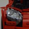
[MOC] Sequential AWD 4-speed gearbox w/ V8
Didumos69 posted a topic in LEGO Technic, Mindstorms, Model Team and Scale Modeling
Sequential AWD 4-speed gearbox with V8 fake engine Features - AWD with center differential - Sequential 4-speed gearbox - One-finger shifter - V8 fake engine This gearbox is an excerpt from my rugged supercar project. The mid-console has an important role in the overall stiffness of that model. It had to be narrow as well. If you build (have built) it, you will also notice it has very little torsional flex. I wanted a 4-speed sequential gearbox covering a wide range of ratios. So not something like 1:2.5 upto 1:1, but rather something like 1:3:5 upto 1:0.8. Another requirement I had, was that I didn't want red clutch gears to transfer drive on axles rotating at different RPM. This is a common practice, but from modding the Porsche I know it induces a lot of friction on the axles involved. When not engaged, red clutch gears better only make dummy rotations and not transfer drive. And finally, all had to fit underneath the engine; I didn't want the gearbox to be routed through the entire chassis. Instructions available on Rebrickable.com. Have fun! -

Is there any 5+R (maybe with +N) sequential remote controllable gearbox?
bekesizoltan posted a topic in LEGO Technic, Mindstorms, Model Team and Scale Modeling
Hi, I'm looking for a reliable remote controllable 5+R sequential gearbox or ideas how to build one. If it would have a neutral as well it would be perfect. Please share your ideas and if you are aware of any kind of existing solution please share the link. Thanks, Zoltan -
[POC] Paddle Shifter Unit
Didumos69 posted a topic in LEGO Technic, Mindstorms, Model Team and Scale Modeling
Scattered over the last few months I've been working on a proof of concept of an improved paddle shifter unit for the Porsche 911 GT3 RS (42056) that uses the stepping principle from Attika's stepper. After several redesigns I finally came up with something that I'm so content with - because of its reliability and sturdyness - that I thought it would not only be valuable as a 42056 MOD but could be of interest to other car builders too. Just like Attika's stepper this setup relies on the interaction with a 90 degree indexer. And just like the orginal 42056 unit it makes use of silicon bands to return the paddles. I tried to hide the silicon bands inside the unit, but that would give too much unbalanced stress to the whole shifting system. The operation is optimal when the bands are close to the paddles. About the operation of the shifters: Each paddle pulls a pusher against a central knob gear independently. When the central knob gear gets pushed over the 45 degree point the 90 degree indexer takes over and completes the 90 degree step. This completion makes the knob gear push the pusher outwards, which allows the pusher to be pulled back into it's starting postion by the silicon band. While being pulled back, the 5x7 frames to the sides of the unit (with their smooth sides facing outwards!!!) make sure the pusher is pulled back inwards too. The video shows a setup that mimics the situation in the Porsche, with the 90 degree indexer integrated in the gearbox. When combined with the indexer, the unit itself can be used in the original Porsche as is. Feel free to add comments or post (suggestions for) improvements. LXF-file here. -
[POC] Compact 90° stepper w/o silicon or rubber
Didumos69 posted a topic in LEGO Technic, Mindstorms, Model Team and Scale Modeling
If you don't like things that use axles as torsion bars, then please skip this topic. In the march of steppers, shifters and limiters, here's my throw at a 90 degree stepper without silicon or rubber. I started off with my compact 90 degree stepper which uses silicon bands for returning the shift lever as well as for limiting the shift axle to 90 degree orientations. Because the rotation movements that had to be limited are quite small (max 10 degrees), using axles as torsion bars seemed to be a valid option that wouldn't put too much stress on the axles involved. After some trial and error I found a setup that actually works. It uses 3L axles with knob and half pins (also with knob) with a flat round 1x1 tile attached to them as stoppers and pole reverser handles as torsion levers. In idle state, there's practically no torsion stress on any of the involved axles. Only when you pull the shift lever, the axles get twisted, but not more than about 10 degrees for the shift lever and even less for the 90 degree limiter. The casing had to be made quite strong to prevent any other bending then the intended axle torsion. LXF-file here. -

Compact Sequential Stepper
Attika posted a topic in LEGO Technic, Mindstorms, Model Team and Scale Modeling
Hello fellows, Let me present my idea for a stepper mechanism for sequential gearboxes (4 speeder). Please forgive me giving such a a short description, but I wanted to share this idea before I take of to my hollyday. I didn't even packed yet and I depart tomorrow So I'll insert the video and copy its description here. I'm going to try to get online every day and react on questons and comments. Finally let me say a big thank you for Didumos69 and his 90 degree limiter for the inspiration. This video meant to demonstrate the stepper, not the gearbox. The nature of this design allows it to be used with almost any kind of gearboxes. I'll make instructions for the gearbox later however I've been trying to show it from every angle in the video so you can attempt to reverse engineer it. It isn't that complicated. Stepper: I've got the inspiration from an other idea what Diederik van Leeuwen came up with. He goes by the name of Didumos69 on the Eurobricks forum. Click on the link below to see his post: http://www.eurobrick.../forum/index... The reliability of this stepper depends on the right rubber rings. For the limiter I was using the small lego silicone ring and for the stepper (the green ring) a non lego one that is much weaker than the white. If it is too strong it pulls the knobwheel back instead of sliding trough on it when it returns to the basic position. So find the right combination by experimenting. It requires the frictionless driving rings in the gearbox. The motorisation can be solved by using PF medium motor combined with return to center mechanism too. Sorry for the lack of quality, it was a hasty work. I hope the point I was gonna make gone trough. If there is any question, please use the comment section. I'll try to answer it as quick as I can. Thanks for watching an reading. Hope you find it usefull. There is a few failed changes in the video, those wre caused by applying shorter route on the handle. This design requires to be turned to the end point (about 65 degrees). UPDATE Gearbox instruction video is uploaded: -
[MOC] Remote Control "RHM Wutzwerg" Supercar
Rage_Hobbit posted a topic in LEGO Technic, Mindstorms, Model Team and Scale Modeling
Link to MOCPages: http://www.moc-pages.../moc.php/426649 VIDEO FOUND HERE: Hello, this is my first post on Eurobricks. Anyway, here I present my custom supercar RHM (Rage Hobbit Motors) Wutzwerg. Note: this model is on Lego Ideas, the link for which is here: https://ideas.lego.com/projects/136011. I'm not really expecting the model to get either the necessary votes or to get turned into a set, but hey, I like to be surprised. Propulsion: 1 x L motor Steering: Front wheel with 1 x Servo motor and working steering wheel Drive Type: RWD Transmission: 4-speed sequential synchronized V2 Weight: 1.3 kg (2.87 lbs) Length: 41.5 cm (16.3 in, 52 studs) Width: 18 cm (7 in, 22.5 studs) Height: 10 cm (3.9 in, 12.5 studs) Power source: 7.4v 8878 Li-Po rechargeable battery box Estimated part count: 1800 pieces Suspension: All-wheel dual-wishbone independent Opening hood, doors, and engine V10 piston engine connected to drivetrain through transmission Build time: ~60 days Short Description This is my first vehicle to be built without a real subject vehicle in mind. It has less of a focus on performance than my other vehicles, with only a single L motor for propulsion. It also has front-wheel steering with a working steering wheel, a new version of my 4-speed sequential synchronized transmission (link here: http://www.moc-pages.../moc.php/422999), and a motorized rear wing. Introduction For this car I was trying something a little bit different. I had just designed a new version of my 4-speed sequential synchronized transmission (link here: http://www.moc-pages.../moc.php/422999) and I wanted to use it in a car, but I also wanted to build something a little less performance-oriented than usual and thus fit in more functions. This time, there is no original vehicle; make what comparisons you will, this car is entirely a product of my imagination. I think. Drive Train Part of my plan for this vehicle was to eliminate one of my customary 2 drive motors, leaving only a single L motor for propulsion. This freed up space for another M motor, as well as allowing room for the V10 piston engine. The V10 piston engine located behind the front seats, and was connected to the drive system through the transmission; as such, it varied with whatever gear the transmission was engaged into. Because of space restrictions, I had to replace the usual cylinder brackets with a custom rig, after spending a solid hour determining the exact geometry of the original brackets. The transmission used in this vehicle works off of the same principle as my previous 4-speed sequential synchronized transmission; this transmission is also a dual-sequential transmission. What this means is that the transmission actually contains TWO separate transmissions which are shifted in such a way as to produce 4 distinct speeds. What differentiated this transmission from the previous versions is that the switches were not hinged: instead, they moved back and forth in a straight line. This can be seen and understood better from the video above, and you can expect instructions sometime sort of soon-ish. The transmission itself was shifted by an M motor geared 10:1. Because of the lessened power from using a lone L motor, the motor had a gear reduction of 1.25:1 before being fed into the transmission, and then another reduction of 2:1 before the differential at the rear wheels. The car wasn’t fast, but it did pretty well for a single motor. Steering and Other Motorized Functions Steering was simple as usual - with a Servo motor and rack-and-pinion system - but this time I added a working steering wheel. That’s just about all there is to say for the steering system. The final M motor was for the rear wing. This was no fancy job, just a linear clutch and lever mechanism to raise the rear wing, but again space restrictions made the implementation of this system difficult. The rear aesthetics were somewhat compromised to make room for the rear wing & mechanism. Aesthetics With this being the first time I’ve ever come up with my own large-scale car, I didn’t really know where to start, and all the online comments saying “Making your own car is SO hard!” were not particularly encouraging. The front was actually the first area to be built (because of the awkward and inconvenient position of the battery box) and the rest of the car was built using the front as a reference point. Obviously, I can’t give my own unbiased opinion on the car’s aesthetics - many hours spent designing it have probably compromised my opinion as well - but I think the aesthetics turned out pretty well. Please, give me your honest opinions in the comments section! Reflections Not bad, I think, for a first attempt at making my own vehicle. Space was a little bit cramped because of the scale I chose to build it in, but everything mostly fit together in the end. It functioned really quite well: the transmission, rear wing, steering, and propulsion systems all worked without malfunctioning even once in the final vehicle, despite considerable use. That may be a first for me. Despite having fun crafting my own vehicle, I can’t see this as being something I’ll repeat frequently. That’s not to say I’ll never do it again, but I do enjoy recreating existing cars, and of course brand familiarity with my viewers gives people something to compare to. Enjoy the pictures! -
Welcome everybody :) Today I’d like to present my new MOC, which was built especially for a contest on LugPol. Fiat 126p Specifications Scale 1:8 Length 51s / width 23s / height 19s (41/18/15 cm) Weight: 2040 g Independent suspension Rear wheel drive RWD 4-speed sequential gearbox AAA Battery Box 88880 Functions Driving (RC) Steering (Servo) Changing gears (L) Front LED lights (switch) R2 dummy Working steering wheel Opened bonnet and trunk Opened doors with lock History I started the building of the model at the beginning of the December, to the Christmas I built chassis, later I created the body. Because of creating the Fiat, I canceled my previous project – Mercedes SLS, becuse it wouldn't fit in the rules of the competition. If you don't know, how the original car looks like, here are the pictures. Drivetrain Fiat is driven by single RC motor. The gearbox is based on Sheepo's one from Veyron. Gearbox ratio: I 5:1 II 3:1 III 1,67:1 IV 1:1 To change gears I used 1 L motor. The ratio is 8:1 (worm gear). Fiat is a bit slow, because at the beginning I didn't want to exceed 1,5 kg of weight, and I hadn't got enough time to improve gear ratio or use 2 Xls. Steering For steering I used servo motor, which propel the gear rack 1x7 with ratio 1,67:1. Suspension The front and rear suspension is independent. I tried to make the rear like the real one, what you can see in the picture. Some photos Gallery
-

Ford Mustang Shelby GT500
Sheepo posted a topic in LEGO Technic, Mindstorms, Model Team and Scale Modeling
This is the car I showed in the Lego Fan Weekend two weeks ago. This creation is made in scale 1:8. The total size is: 75 studs of length, 29 wide and 21 of high (60x23x17 cm) The weight is 3.1 kgs, with around 3500 parts and 5 motors. It includes some remote controlled functions: - Steering (M motor) - Drive (2 L motors) - Sequential gearbox (PF Servo motor) - Disc brakes (M motor) The sequential gearbox is an improved version of my previous Caterham ones (3rd Gen V2), with 5+R and auto-clutch. The speeds ratio: R - 2.08:1 1 - 1.67:1 2 - 1.25:1 3 - 1:1 4 - 1:1.33 5 - 1:1.67 The max speed in 5th speed is 3 kph (~2 mph) It has a gear indicator in the interior, between the front seats. For make more easy the gearbox tests the car in has a rear support to keep the rear axle lifted The suspension is based in the real one: front McPherson axle and a rear 4-links live axle. The front axle also has advenced geometry: Camber angle(2º), caster angle(3.5º) and kingpin angle(7º) The steering has ackerman geometry and working steering wheel. The car also has working disc brakes in all wheels, they are very powerfull and includes functional brake pedal. The complete video COMPLETE INSTRUCTIONS WILL BE AVAILABLE COMING SOON!! As always for more info visit my website: sheepo.es -
Sheepo's Sequential Gearboxes Family
Sheepo posted a topic in LEGO Technic, Mindstorms, Model Team and Scale Modeling
Today is the third anniversary of my website!! And for celebrate it I will show you many information about all my sequential gearboxes until today. With my latest cars I introduced a new sequential gearbox type, and to avoid problems with how to call this new one, I decide add a new way to call all of them. Since now the new versions of the sequential gearboxes will be called with ordinal numbers. In this ordinal numbers don't enter other gearboxes types like: dual clutch, planetary or CVT, just normal sequential gearboxes. 1st Generation This was my first sequential gearbox(I think this was the fisrt Lego sequential gearbox with more than 3 speeds, but I am not sure), I designed it in 2009 to be used in my Bugatti Veyron. The version used in my Veyron is a 7+R speeds. with a little modifitacions you can get a 4 speeds or a 5+R speeds versions. The main feature that distinguishes this generation is that it has a speed selector in linear motion, and the distance between speeds are 2 studs. Correct speeds change ratio: ~70% In Octuber 2010 I designed a second version with auto-clutch. It worked fine, but I decide not publish it beceause it was too big to be used in any car. 2nd Generation Before to finish the Veyron, I started to develope a new car(the Porsche), and even before I know what car I will build, I wanted to use again a sequential gearbox, but the Veyron's gearbox wasn't an option because it was too big. In the search of a new smaller gearbox I developed many differents prototypes. And this was one of them. Finally I decided to use a dual-clutch gearbox to be more accurate to the real Porsche. The main feature that distinguishes this generation is that it has a speed selector in linear motion, and the distance between speeds is only 1 stud. I have used this gearbox in 3 of my big MOCs until today, all of them with differents speeds configurations and add-ons. Type 1 - 2 switches(4 speeeds), without auto-stop, without clutch (Mini Cooper) Correct speeds change ratio: ~90% Here the Mini's gearbox. It was the first You can download the step by step instructions in my website. Type 2 - 3 switches(5+R speeds), with auto-stop, with auto-clutch (Land-Rover Defender 110) Correct speeds change ratio: ~80-85% Here the Lad-Rover drivetrain. This drivetrain also includes a range gearbox and a 2WD/4WD selector, but the sequential gearbox is a normal 2nd Gen gearbox. Type 3 - 5 switches(9+R speeds), with auto-stop, with auto-clutch (Peterbilt 379) Correct speeds change ratio: ~80-85% Here you can see the whole Peterbilt drivetrain. You can se the main gearbox, the drive motors, the range gearbox and the pneumatic module(compresor, compresor control and brakes control). In total 5 PF XL motors and 3 M. 3rd Generation The history of this gearbox is very strange. Like the 2nd Gen, this gearbox was initialy developed as a alternative gearbox for the Porsche, but in this case I couldn't make a good system to generetare the auto-stop mechanism, so I leave it in a box of a while... The main feature that distinguishes this generation is that it has a speed selector in circular motion. To reduce the size of the few speeds versions I created two types: one for 2 swtiches and another for 3 and 4 switches. Type 1 - 2 switches only This type change one speed for each 90º of the selector switch movement. Correct speeds change ratio: >95% I will publish some information about it comming soon. Type 2 - 3 & 4 switches This type change one speed for each 45º of the selector switch movement. This gearbox is specialy recomended for 4 switches, because with only 3 switches the saved space compared to the 2nd Gen is not significant, maybe around 5-10%. But with 4 switches the saved space is more than 20% Version 1 (V1) - Caterham Seven (with auto-stop, with clutch) Correct speeds change ratio: ~85-90% This new gearbox is more reliavable than the 2nd generation, but it still have a little problem, and I need to fix it before publish nothing more about it: it can't support high torque. I could avoid this problem in the Caterham adding an external torque converter, but this is not the ideal way to do it. Here you can see the Caterham Seven drivetrain. Version 2 (V2) - Ford Mustang Shelby GT500 (with auto-stop, with clutch) Correct speeds change ratio: ~90-95% This is a little bit smaller and more reliavable version of the 3rd gen. And with the torque problem fixed. Here the Mustang GT500 drivetrain. Future generations For the future I have some ideas for new gearboxes generations, but they are only ideas... nothing more, and I don't know when I will can have a working prototype. I hope this long explanation can help you to understand my gearboxes family and the high quantity of models developed along the years. -

Sequential Gearbox 3+R with clutch
piterx posted a topic in LEGO Technic, Mindstorms, Model Team and Scale Modeling
Hi guys! I was a bit unsure to post it before putting it in the car I'm building but: here's my sequential gearbox based on sheepo's one...it's smaller, only 15x13 studs and it has the one way clutch to separate it from the engine. At the moment it only has 3 gears + R because i had only 2 red gear selectors :P but you can easily extend it to 5 or more... My aim was to make something small and light (as always lol) Unfortunately i havent enough english skills to describe exactly how it works but it should be pretty clear :D It has'nt the "snap" that the sheepo's version has, so you need to pay attention when you shift gears because you can get into the neutral...but I'll try to adapt it with servo motor to make it more precise... though it's good enough. I hope you like it and you'll be able to improve it for the community's benefit :) -> some pictures to let you re-build it here's a detail of the "sled" used to move the yellow pins.... the white rim is the one way clutch (that i wrongly called "free wheel" lol) anyway, the M motor can easily be placed somewhere else, that was the fastest option i choosed :P hope this is gonna be useful for you all SHARE OR DIE !!! -
4 speed sequential gearbox (servo motor shift gear system)
Jeka Jackson posted a topic in LEGO Technic, Mindstorms, Model Team and Scale Modeling
Hi everyone! I'm glad to represent my 4 speed sequential gearbox using servo motor in its shift gear mechanism. Gear rations: 1 - 1:5 2 - 1:3 3 - 3:5 4 - 1:1 Photo & video you can see here: http://www.doublebrick.ru/blogs/jackson/4-h-stupenchataya -
I have the pleasure to present you my latest moc. The Caterhan Seven (also called Caterham 7) is the present version of the original Lotus Seven (or Lotus 7) designed by Colin Champan in 1957. This car is very famous because it is extremly ligth, and it has outstanding dinamic specs, which make this car perfect for its use in competition and track days. The original: This creation is made in scale 1:7. Thus remains in 29 studs wide, 56 of length and 20 fo high(23x45x16cm). The weigth is 2.2kgs. It has around 2500 parts. As all my MOCs, this includes some remote controlled functions: - Steering (PF M motor) - Drive (PF 2XL motors) - Sequential 5+R speeds gearbox (PF Servo motor) - Disc brakes (PF M motor) This car arrives with a 5+R speeds version of the all-new 3th generation of my sequential gearboxes. The new generation is even more compact and reliable. Of course it has auto.clutch It has a gear indicator in the cabin. Just behind the seats, over the rear axle are the battery and the drive motors (2XL) The Seven design is based in a tubular unibody frame with double wishbone front independent suspension and DeDion rear live axle. The front axle is double wishbone type with caster angle, camber angle and ackerman steering. The original Lotus 7 had a typical rear live axle, and the newest and powerfull version has independent suspension , but the most common rear axle is the DeDion axle. Like the real one, this creation has rear 3-links DeDion axle(you can see it in more detail in the video) The "most wanted" picture. This creationa also has working brakes in all wheels(the same brakes used in my Land-Rover) Like the real Seven, this creation mantains the unibody frame. Also to reduce the weigth, the frame and the bodywork are the same thing. The yellow liftarms in both sides of the car are the bodywork, but at the same time are the frame of the car. This picture shows how the structure is made As always a little video: For more info and pictures you can visit sheepo.es Fernando