Search the Community
Showing results for tags 'Ev3'.
Found 184 results
-

Gear Grinding/Clicking Issue In Gearbox (EV3)
StudRobotics posted a topic in LEGO Technic, Mindstorms, Model Team and Scale Modeling
I'm building a SUV drivetrain for my Lexus GX EV3 project that has independent suspension, four-wheel-drive, and a four-speed gearbox with a medium EV3 motor that shifts the gears. Unfortunately, after testing the drivetrain, I found that when in 3rd or 4th gear, the gears make a clicking noise when moving forward and then straight to backward. However, this clicking somewhat occurs less when going from reverse to forward. This clicking really "grinds my gears" and I don't know what to do to stop the gears from clicking. My gearbox is a custom version of Sariel's four-speed sequential that is fit for the vehicle I am building. The input in the transmission is switched to provide more speed. Two large EV3 motors drive the input. I've noticed that when the vehicle stops, it goes the opposite direction for a little bit. Also, like I already said, this clicking only happens in 3rd or 4th gear, but mostly the 4th gear since it brings the most speed. I tried to solve this clicking with different gears and whatnot, but no matter what they still clicked when the vehicle moved forward to backward. The motors and the gearing also bring a lot of torque as much as it brings speed, and this might be one of the problems. Is there any way I can solve this issue so the gear clicking will stop in this situation (moving foward and then straight to backward) for now on? Here's a photo of the bottom of the drivetrain. Thank you in advance for any assistance that you may be able to provide! -
Hi, i've been working on this platform for a while, now it's basically ready. It's a tank with 6 indepentent suspension (3 per side), remotely controllable with quite a powerful climb :) It has space to put something else on it such as a weapon or a crane or such. Here's some pictures (sorry for the blurrines): The shell without threads and EV3: I've also attached a webcam to it, i was able to stream a 160x120 live video and drive it around the garden remotely, pretty awesome if a bit blurry :P Unfortunately i had to use an USB hub which have a huge plug, i had to put the EV3 brick vertically or it wouln't fit. At least there's just the right space to put the hub :) Here's some render too:
-
 In the Netherlands, in the last class of the secondary school, you have to write a study project (for the Dutch: "een profielwerkstuk"). My son (17) choose to build the soccer robot from the Eindhoven University. More information about the real robot can be found here: http://www.techunited.nl/en. For the study project, my son wanted to know if it would be possible to build a single robot with the same functionality as the real one, meaning: The robot should drive in any direction using omni wheels The robot can see the ball The robot can drive towards the ball The robot can grab the ball The robot can shoot the ball The robot 'knows' its location on the playing field The robot has been build by Lego Mindstorms, with a total of 4 EV3 bricks, 9 large motors for the movement of the robot, a Pixycam camera for the vision, 2 large motors for grabbing the ball and 2 medium motors for the shooting. A gyro sensor is used to make sure that the robot only makes one full turn (360 degrees) when it is searching for the ball. Apart from the Pixycam, everything is regular Lego. The result of his study project is shown on the picture below. The robot is able to drive, locate the ball (it should be in a range of 2,5 meters otherwise the camera won't see it), drive to the ball using a simple PID control algorithm, grabs the ball and shoot the ball (if you click on the picture below you will be teleported to my Flickr page containing more images of the robot): Last Saterday, during the open house of his school, my son was invited to demonstrate the result of his study project to the visitors. A small video of the robot during the demonstration can be viewed on my Youtube channel. Please let me know what you think of his study project. And if there is more interest, I can post some more details. Kind regards, Hans
 -

Fully automated LEGO Mindstorms factory with laser cutting
andreasbaumgart posted a topic in LEGO Technic, Mindstorms, Model Team and Scale Modeling
Papercube is a fully automated Lego "factory" created by students and me Germany's Jade Hochschule. It is a scale model of an actual production line. The machine takes a piece of paper and runs it through a series of processes that manipulate it into a paper cube. The paper is then perforated by a laser to outline the shape the cube will eventually take. The laser is enclosed in a protective, orange casing to protect the eyes of anyone watching this process. Enjoy our video :-) Andreas -
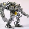
[MOC] EV3 Koenigsegg Regera (1:10)
TheMindGarage posted a topic in LEGO Technic, Mindstorms, Model Team and Scale Modeling
Well, I didn't update the WIP, and I ended up nearly two months behind my prediction, but I've finally finished it! And as far as I know, this is the first large-scale TECHNIC model of this car published online! The real Koenigsegg Regera is a groundbreaking "megacar" featuring a 5-litre V8 and three electric motors for a combined 1,479hp (1500PS). But it has no gearbox. Instead, there is one electric motor for each wheel, plus another electric motor coupled to the V8. The electric motors have instant torque and so the car doesn't need a gearbox to reach 250mph in 20 seconds! So, the full list of features: Remote-controlled drive - top speed is around 8mph Model of the real car's drivetrain Full independent suspension Castor angle on front axle (this is really important - you'll see why later) Triplex anti-squat bar on rear axle Adjustable camber angle and suspension stiffness for all four wheels - each wheel can be adjusted independently Synchro-dihedral doors Raisable rear wing Opening rear hatch to reveal "engine" bay Cabin with two seats, floor and steering wheel The drivetrain starts with a Large motor and a Medium motors (using different gearing). They are hard-coupled, but the gear ratios match very well and the EV3 can control the power it sends to each motor to make sure they aren't forcing each other to speed up/slow down. These motors drive a differential, with one Large motor on each side of the diff, just like in the real car. Then each output is geared up 1:9 to give the required speed - it's kind of a reverse portal-axle. Since the car isn't too heavy (it's about 1.4kg), the bevel gears aren't stressed that much, even with all this gearing up. I made a simulated dyno graph showing wheel torque and power with wheel speed in mph. This uses the official LEGO specifications of the motors and assumes no drivetrain losses: The front suspension is rather complex. All the adjustment controls are shown here: Now, you may have noticed there is NO steering rack. This is deliberate because it allows me to have an extra motor for driving. Instead, the motors on either side of the differential run at different speeds to steer, rather like a tank or castorbot. This is why it's so important that the castor angle is high. The top wishbones are able to slide in and out by 1 stud to change the camber angle. Just in case you wanted to put stance on your £1.9m megacar. The suspension uses both a torsion bar and a conventional shock absorber. The torsion bar's attachment point can be adjusted with a worm gear, allowing the suspension's stiffness to be changed. The rear suspension uses the same shock/torsion bar setup, but with an extra shock absorber between the wheels. This is what Koenigsegg calls Triplex, and it allows softer anti-roll-bars to be used (on this model there are none). The rear opens up to reveal the rear suspension. You can see the 24-tooth clutch gears here - those are to keep the rear wing in position. The doors are one of the most fun parts of this build. The doors slide forwards, outwards and rotate, all at the same time. They reveal the cabin. Unlike my previous models where the cabin is made a little smaller, the cabin in this model is proper-size. The aesthetics were very difficult. Because the front was so low, I decided to incorporate the suspension wishbones into the bodywork. I decided to exaggerate the front bumper, since to me that part of the real car stands out. I don't have any flexible axles, so I used pneumatic hoses for the windscreen. Since the roof's dome shape is very awkward to build, I decided to build it without a roof (all Regeras have removable roofs)! The side air vents don't widen enough towards the rear wheel - they look more like those on the Agera and CCX. Unfortunately, I don't have the right shapes of panels to make the vents properly, so I had to use a little artistic license. The air intakes on top of the car (behind the seats) stood out to me, so I made those prominent. Some have said it looks a bit like a 918 or Carrera GT. I also decided to exaggerate the rear diffuser - it looks almost Lamborghini-like to me (maybe a Veneno). And for some reason, the whole thing conjures up images of a McLaren F1 Longtail - I'm not sure why. But I guess if you combine the F1's speed, the 918's hybrid innovation and the Lambo's flair and doors, you pretty much have a Regera. Wow, that wasn't intended :P. Finally, here's a video I made. You can see a time-lapse of the building process, the suspension in action and the door mechanism exposed! I compose all my own music for videos - I hope you like it! -
[MOC] Tomik's EV3 Lab
Tomik posted a topic in LEGO Technic, Mindstorms, Model Team and Scale Modeling
Hi all, since I recieved Mindstorms EV3 set 31313 few days ago I've decided to start my first project. I call it CLEV3R CAR and as you can guess it's about car. I've just finished building it and I'm about to start programming it. So let's talk about model first. It looks like Mini Cooper, chassis is inspired by RAC3 TRUCK and I've finished it in just two days. It features two large motors for driving, medium motor for steering, IR sensor instead of radiator and rear bumper with touch sensor. I wanted to build it as small as possible but it became pretty big. I've paid attention to many details so you can easily remove EV3 brick (for example to change batteries) and there is enough space under it so you can use it with original rechargable battery as well. It's also pretty sturdy, I plan to program several modes for it: Automatic - independent driving with avoiding obstacles RC - remotely controlled from IR beacon with driving assistance (for example if you drive it against wall it will stop before it) Search for beacon - independent driving to beacon By the way does anyone have experience with programming searching for beacon? I can imagine how to do it for tank (or other tracked vehicle that can turn on the spot) but car with classic steering is something different... -
Sioux.NET on Track presents the Ticket Dispenser Unit (TDU) Two articles about the Lego Dispenser Unit can be found at our blog: https://siouxnetontrack.wordpress.com/2016/09/28/ticket-dispenser-unit-reader/ In this article you can read how tickets are read using a four-color based number system. This article was written before the dispenser part was created, so it is only about the reader part. https://siouxnetontrack.wordpress.com/2016/12/28/ticket-dispenser-unit-complete-version-2017/ In this article you can read about the upgraded version that will be used at Lego World 2017. Click on the following picture to see more pictures: A video of the working TDU 2017 can be found here:
-
Sioux.NET on Track @ Lego World 2016
Hanso posted a topic in LEGO Technic, Mindstorms, Model Team and Scale Modeling
At our Flickr page you can view the photos of our visit at Lego World 2016 in Utrecht: https://flic.kr/s/aHskMd9EAj. A video is also available: Enjoy, Hans -

EV3 GBC starter module?
Huaojozu posted a topic in LEGO Technic, Mindstorms, Model Team and Scale Modeling
I have recently become interested in the art and science of GBC and I am looking for the best way to start building. One problem though, I don't like to mix my sets . I have seen some great GBC c-models (such as https://www.youtube.com/watch?v=lb5kTm9Ykn0 ) but unfortunately haven't been able to find any instructions. In particular I am looking for simple GBC modules made of single sets to study the entire GBC mechanic and learn from it to make my own modules. It doesn't really need to be fancy or cool, just functional and c-model-ish. Has anyone come across something similar? It seems that in all topics I've found, the possibility of making modules as c-models of existing technics sets isn't really discussed. -

[EV3] Advanced Programming
johannp02180 posted a topic in LEGO Technic, Mindstorms, Model Team and Scale Modeling
I am new to this blog and don't know how things work yet. I have a few questions about some programming I am having trouble with and wanted to see if the community can provide me with some programs they've built. 1. I want a program so that you can press the touch sensor ex. 2 times, it would run the 2nd program; press the touch sensor 4 times it would run the forth program etc. Or have a color sensor and I put a red brick in front of it and it runs a specific program. 2. I have a wall follower program and I am wondering if it can follow the wall for about 24in or so and then stop and do some other action. Does anyone have an idea on how to do this, and can you provide a program? I can't figure out how to program these. Any tips, programs, would help! -

Lobst3r, a walking robot
Aswin posted a topic in LEGO Technic, Mindstorms, Model Team and Scale Modeling
This is Lobst3r, the walking robot that can walk in any direction. It goes forward, sideways, it can turn and even rotate on the spot. Robots that can go in any direction are called holonomic or omnidirectional robots. Most holonomic robots are made with special wheels. This robot however is a walking robot. Its legs implement Klan linkage to walk. But the real trick is in the toes of the legs. The wheel on the tip of each leg is the secret to its holonomic capabilities. This small wheel is mounted perpendicular to the direction of the leg. As a result, the leg can roll sideways without any friction whilst still having friction in the walking direction. The base of the robot is triangular, the simplest form to create a holonomic robot. On each side are 4 legs that are linked to a single medium EV3 motor. An additional NXT motor under the tail of Lobst3r powers the claws of the robot. The robot has two ultrasonic sensors that are used to detect objects in front of the robot. If it sees an object it will try to walk around it. If that doesn't work it will snap it claws in self defence, back up, rotate and walk away. The US sensors are switched on and off to prevent one sensor picking up the echo's from the other sensor. As a result the robot seems to blink with its eyes The program is written in leJOS. LeJOS offers standard code to implement holonomic robots. -
[WIP] Koenigsegg Regera EV3
TheMindGarage posted a topic in LEGO Technic, Mindstorms, Model Team and Scale Modeling
At the moment, this is just an idea - since I have two cars currently half-build, I will finish them before doing this. Expect this sometime in October (knowing me, near the end of it ). This will be about 1:10 scale with 68.8x36ZR tyres. As with all my cars, this won't be a strict scale model - I just want the car to be recognisable, functional and fast. These are my plans: Power will come from my entire EV3 arsenal - 3 EV3 Large motors and one EV3 Medium motor. These will be connected in a very strange way. The Large motor and Medium motor (geared down 5:3) are combined with an adder. This output will go into a second differential with one Large motor on each side. Each side will then be geared up (hopefully 1:9) before going to the wheels. I haven't tested this setup - I really hope the diffs are strong enough . I might need to gear up the motors 1:3 before the diff and 1:3 after the diff, but I'd rather avoid this if I can since it would mean more sets of gears. When turning, the Large/Medium combo (representing the ICE) will have to slow down a little bit, as will the Large motor on the inside of the turn. Steering will not be motorised - my plan is for the front wheels to be able to steer freely (maybe with a rubber band to provide a little self-centering) but have a high castor angle. When the motors on each side of the diff turn at different speeds, the front wheels will steer automatically. Essentially the fastest castorbot ever! Suspension is still undecided. Depending on the layout of the drivetrain and my chosen width (the math says 26 studs - I have a choice of 25 or 27), the rear suspension may either be independent or an independent trailing-arm type. Whatever I go for, I would like something that replicates the triplex suspension in the real car. Front will be regular independent, with the wheels free to pivot. Making the ride height adjustable would be a bonus. I'm also hoping to make proper Koenigsegg doors and have some space for a cabin. -
Sioux.NET on Track is a group of enthusiastic colleagues who come together after working hours to get experience with Microsoft.NET. To make learning fun, we develop an application in C# for making a full automated Lego train, using Lego Mindstorms and Lego Power functions. The layout is always shown at Lego World in the Netherlands. Our plans for 2016 have been published at our blog: siouxnetontrack.wordpress.com as well as an article about the new updated crane positioning. You can also view a video at our Youtube channel about the power chain systems: Enjoy, Hans
-

[EV3] Mindstorms High Performance SUV
DamonMM2000 posted a topic in LEGO Technic, Mindstorms, Model Team and Scale Modeling
Last month marked the second anniversary of my YouTube channel, so I decided to recreate the first video I posted: a high-speed Sport Utility Vehicle. In different ways, my production skills have improved, and in other ways, not as much. I think I still have a lot to work on... do you guys have any suggestions? I'd like to know how my videos are perceived. Thanks to all who have been watching my videos and have subscribed! -
[EV3] Rally Racer
DamonMM2000 posted a topic in LEGO Technic, Mindstorms, Model Team and Scale Modeling
Rally Racer is the successor of Rally Rac3r. The difference? This Rear Wheel Drive race car is a tremendous success. As complimented by Karl4123, this vehicle has "sleek and stylish looks." It is geared up 36:12 or 3:1, and it is decently quick with decent torque. Many styling cues have been added. Why is there no InfraRed Sensor, you may ask! Well, thank you for asking! With the help of Builderdude35's tutorials, Rally Racer drives via Bluetooth! Rally Racer's Intelligent Brick acts as a receiver, and a second Ev3 Intelligent Brick is the remote! In this way, I am able to control Rally Racer from 200 feet away. Rally Racer features twin dual exhaust. The taillights feature vents which mimic the outsource of airflow, similar to that of the Ferrari 488 GTB. The spoiler is a low, lean downforce-inducing wing. The headlights are a twin-cluster with a main headlight and an auxiliary tinted light, not including the rally style fog lights. The chassis is extremely compact in and of itself. I borrowed the drivetrain design from Builderdude35's Falcon FAV100, so thanks! Two Large Motors drive a 36z gear which drives a half-bevel 12z gear (these are encased about an H-frame). It then transfers drive both to the front and rear of the robot. There is a differential which transfers power to the rear wheels, while the front axle extends to the front of the car as a neat auxiliary cue. The rack and pinion steering setup is controlled by a Medium Motor, and stabilized with a LEGO rubber band. Check out the metallic exhaust tubes while you're at it! Please comment if you have any questions or... comments. I appreciate any feedback whatsoever. I am quite please with how this turned out, especially when comparing this with my original Rally Rac3r model. -
[EV3] Technic Jim's Mindstorms EV3 Thread
Technic Jim posted a topic in LEGO Technic, Mindstorms, Model Team and Scale Modeling
Hello all! It has been a while since I have posted here but I have got a new toy! It is on loan to me for the summer and I plan to use it well. This thread will be where I post all my creations and hopefully the programs. I have a few programs ready and waiting to be filmed and a lot more ideas. None of them have been filmed yet, but here is a trailer to wet your appetite!: As usual, please leave any constructive feedback and keep popping back because I will (probably should!) be updating this thread fairly often. Technic Jim -
[MOC] Nissan GTR with EV3
TheMindGarage posted a topic in LEGO Technic, Mindstorms, Model Team and Scale Modeling
This is my first MOC on this site! Bear in mind that I have only been building for slightly more than 2 years and don't have a very large collection, so my builds aren't exactly Sheepo standard... The car is a 1:10 model, although I had to deviate from the scale slightly in order to fit the functionality I wanted into the car (width was increased to 25 studs for example). Here are the features (LONG list): Remote control drive with three EV3 Large motors. Top speed around 5mph. Drive goes to all four wheels via two diffs. Remote-control steering with EV3 Medium motor. Turning radius is rather large though. 8-speed automatic hybrid gearbox. Basically a 4-speed automatic and a 2-speed ratchet gearbox (inspired by Sariel) used together. A model piston engine (V6) in the front with engine capacity scaled to the real car (I measured mine at 3.77cc, real car is 3.8l). Lever in cabin with Drive/Neutral/Brake settings. Handbrake system and rear friction brakes. Full independent suspension with negative camber angle. Adjustable ride height for each wheel through tuning dials (front ones are under the hood, rear ones are hidden next to the spoiler). Adjustable castor angle for each of the front wheels (adjusted by rotating the turntables). Opening sprung doors with locks. Opening sprung front hood. Cabin with fake steering wheel (non-rotating), FOUR SEATS and a floor. Pic with doors and hood open, revealing the model engine. The red pads on the hood are rubber friction pads (from EV3 Education Expansion set) - these keep the hood closed. Close ups showing the piston engine and suspension. When the tuning screws are turned, a worm gear system rotates the arm where the shock absorbers are mounted. Adjustment range is about 2 studs. Castor is adjusted by turning the turntables - this effectively rotates the entire suspension system relative to the chassis. Beams from the chassis are placed to interfere with the rotation of the turntables - this keeps the turntables in place when not adjusted. The cabin is fitted with a full set of 4 seats, as in the real car. The occupants of the rear seat are given the rare treat of having gears from the 2-speed ratchet gearbox right next to them. When the drive setting is enabled, a driving ring allows the motors to drive the 4-speed gearbox. In neutral, the driving ring meshes with nothing, letting the car roll freely. In Handbrake, the driving ring locks the input shaft of the 4-speed gearbox to the output using a gear ratio that isn't part of the gearbox, effectively locking the shaft. This is like solving the equation 3x=x (x is the rotation speed of the shaft) - x can only be zero. Part of the drivetrain is shown here. The differential and elastic system measures the resistance on the input. The system on the bottom-left shifts gears when the resistance is too low or high. The 4-speed gearbox is a standard 5/3/1.67/1 design - the 2-speed's gear ratios fit "in between" these. Notice the towball links and lever below (remember this is an upside-down view) the gearbox. Those control the rear brakes. In Handbrake mode, the brakes are engaged. Here is a graph showing the 8 power bands (created with Microsoft Excel). The lines are cut off when the spreadsheet calculates that the motors run out of torque. This graph used data from my test runs, so the performance shown here is similar to that in real life. Top view of the rear with the body removed. The drive motors are visible, and the 16-tooth gears (used as tuning dials for the rear suspension) can be seen. This is the underside of the rear axle. When the towball link is pulled, the red rubber pad swings outwards and grips the inside of the wheel. I made the rather radical decision to leave the EV3 brick exposed at the back. I decided that covering it up would require too many parts, add too much weight and deviate from the scale. The GTR's four red rear lights are modelled with new-type 16-tooth clutch gears. Overall, I think this has been a successful build for me, cramming in far more features than any of my prior builds (in fact, I am yet to see a 1:10 supercar model with more functionality). However, some things could have been improved: It isn't a perfect scale mode. The seats are way too far forward - I had to do this to fit the monstrous powertrain inside. The rear end aesthetic requires, well, some getting used to. Rear wheels sometimes rub against the top of their fenders. Can be solved by setting the tuning to maximum ride-height. Negative camber angle is too pronounced. Steering lock is very small, and gets even smaller if castor angle is set to extremes. Gearbox tends to be rather "reluctant" to shift gear - this was the only way to stop it from constantly alternating between two gears. It isn't exactly GTR like when driven. GTRs are known for their acceleration, but the model takes ages to get up to speed. It drives more like a truck. My next build will be my Porsche competition entry - no EV3 will be involved for that, although plenty more features (did someone mention 4-wheel steering?)... -
[HELP] Lego EV3 Calculator
Technic Jim posted a topic in LEGO Technic, Mindstorms, Model Team and Scale Modeling
Hello all, I have been working on a Lego EV3 calculator recently and have incorporated quite a few functions into it.However, there are two functions I would like to add that I don't currently have. The functions that are already in it are as follows: Add Subtract Multiply Divide Exponential Square root Factorial (this was a pain to make!) Sin ASin Cos ACos Tan ATan The two that I would like to add are an Xth root of Y function and a Log() function. If anyone knows any way I can program these blocks or any ways you have seen yourself, please post a reply! Thanks, Jim -
I'll call LEGO customer service in the morning (actually later today, yes I am up late ). Hoping someone here has a quick fix. I have a new EV3 brick with rechargeable battery. Recharged the battery while attached to the brick, the brick was initially on, then auto-powered off about half way through. Now, the brick will not turn on - the center button does not move nor can it be depressed - no 'click' when pressed, left/right up/down back buttons all 'click' as normal. Any thoughts on how to reset or what's up. I get the same result regardless if rechargeable or AA alkaline batteries are used.
-
 Teaser: Introduction The article describes the experience of using the Lego Mindstorms EV3 set for creating a robot prototype with software and manual control via Robot Control Meta Language (RCML). Next, we will discuss the following key points: Assembly of the robot prototype from the Lego Mindstorms EV3 set. Quick RCML installation and configuration for Windows. Robot software control based on EV3 controller. Manual control of the robot peripherals using a keyboard and a gamepad. Jumping a little ahead, I will add that for implementing control over a Lego robot via a keyboard, one will have to create a program containing only 3 lines of code. More information about it is available under the cut. Step 1 First, the Lego Mindstorms EV3 set was used for creating a prototype robot to be used for programming and manual piloting. The robot's design is similar to that of a truck chassis. Two motors installed on the frame have one common rotation axis connected to the rear wheels via a gearbox. The gearbox converts the torque by increasing the angular speed of the rear axle. The steering system is assembled on the base of a bevel gear speed reducer. Step 2 The next step is RCML preparation for working with the Lego Mindstorms EV3 set. Download the archives with executable files and library files rcml_build_1.0.6.zip and rcml_modules_build_1.0.6.zip. The following describes the quick start procedure for ensuring interaction between RCML and the Lego robot controlled by an EV3 controller. Content directory after extracting the archives Next, one has to create configuration file config.ini to be placed in the same directory. To implement control over the EV3 controller via a keyboard and a gamepad, connect modules lego_ev3, keyboard and gamepad. Listing of configuration file config.ini for RCML [robot_modules] module = lego_ev3 [control_modules] module = keyboard module = gamepad Next, the EV3 controller should be paired to the adapter. The instruction for pairing an EV3 controller to a Bluetooth adapter: The reference guide contains an example of pairing a Lego Ev3 controller to a PC running under Windows 7 operating system. Next, go to the Ev3 controller settings and select menu item "Bluetooth". You should make sure that you have set the configuration settings. “Visibility” and” Bluetooth” should be ticked. Go to "Control Panel", select "Devices and Printers", and "Bluetooth Devices". Click on the "Add device" button. A window with available Bluetooth devices will open. Select "EV3" device and click "Next". Dialog box "Connect?" will be displayed on the EV3's screen. Check as appropriate and confirm by pressing the center key. Next, the "PASSKEY" dialog will be displayed, enter digits "1234", and confirm the key phrase for pairing the devices by pressing the center key at the position with the tick image. In the pairing wizard of the device, a form for devices pairing key will appear. Enter "1234" and press "Next". A window with confirmation of successful device connection will appear. Press the "Close" key. At the PC, return to "Control Panel", select "Devices and Printers", and "Bluetooth Devices". The paired device will be displayed in the list of available devices. By double clicking, go to “EV3” connection properties. Next, go to the "Hardware" tab. By double clicking, go to the connection properties of the "Standard Serial over Bluetooth link". The COM port index specified in the properties should be used in the config.ini configuration file of the lego_ev3 module. The example shows Bluetooth connection properties of a Lego EV3 controller with the use of a standard serial port COM14. Further module configuration is limited to specifying the address of the COM port used for communication with the Lego robot in the configuration file of the lego_ev3 module. Listing of configuration file config.ini for the lego_ev3 module [connections] connection = COM14 [options] dynamic_connection = 0 Now configure the keyboard module. The module is located in the control_modules directory, then keyboard. Create configuration file config.ini next to the keyboard_module.dll file. Before creating a configuration file, specify the actions to be performed by pressing keys. The keyboard module allows using keys with a certain numeric code. The table of virtual key codes is available here. As an example, I will use the following key press events: The up/down buttons are used to rotate the rear wheels motor forward/backward. The left/right arrows turn the wheels left/right The configuration file of the keyboard module describes which axes are available for the programmer to implement interaction with the robot in the manual mode. Thus, in the example we've got two control groups - these are keyboard axes. To add a new axis, stick to the following rules of axes description. Rules for describing axes for the keyboard module. 1. In case of adding a new axis, add axis name property to section [mapped_axis] and set it equal to the value of the keyboard key in HEX format; there may be several keyboard button values for one axis. In general, an entry in the [mapped_axis] section will look as follows: axis_name = keyboard_button_value_in_HEX_format 2. You should set the maximum and the minimum values that the axis may take. To do so, add to the config.ini configuration file a section named as the name of the axis, and set the upper_value and lower_value properties for passing the values of the axis' maximum and minimum. In general, the section looks as follows: [axis_name] upper_value = the_max_axis_value lower_value = the_min_axis_value 3. Next, you should determine what value the axis will have after a previously defined button on the keyboard is pressed. The values are defined by creating a section with the name consisting of the axis name and the value of keyboard button in Hex format, separated by underscores. To set the default (not pressed) and pressed state values, unpressed_value and pressed_value are used, where the values are passed. In general, the section in this case will look as follows: [axis_name_keyboard_button_value_in_HEX_format] pressed_value = axis_value_with_pressed_button unpressed_value = axis_value_with_released_button To implement the control over the robot prototype, a configuration file of the keyboard module has been created, which includes the "go" and "rotate" axes. The "go" axis is used to indicate the direction of robot movement. When the “up arrow” button is pressed, the axis is set to 100, and when the “down arrow” button is pressed, the axis is set to -50. The rotate axis is used for setting the front wheels turn angle. When the "left arrow" button is pressed, the axis is set to -5, and when the "right arrow" button is pressed, the axis is set to 5. Listing of configuration file config.ini for the keyboard module. [mapped_axis] go = 0x26 go = 0x28 rotate = 0x25 rotate = 0x27 [go] upper_value = -100 lower_value = 100 [rotate] upper_value = -100 lower_value = 100 [go_0x26] pressed_value = 100 unpressed_value = 0 [go_0x28] pressed_value = -50 unpressed_value = 0 [rotate_0x25] pressed_value = -5 unpressed_value = 0 [rotate_0x27] pressed_value = 5 unpressed_value = 0 Next, for control implementation using a gamepad, configure the gamepad. Configuring the module includes creating configuration file config.ini next to gamepad_module.dll in the control_modules directory, followed by gamepad. Listing of configuration file config.ini for the gamepad module. [axis] Exit = 9 B1 = 1 B2 = 2 B3 = 3 B4 = 4 L1 = 7 L2 = 5 R1 = 8 R2 = 6 start = 10 T1 = 11 T2 = 12 RTUD = 13 RTLR = 16 LTUD = 15 LTLR = 14 arrowsUD = 17 arrowsLR = 18 [b1] upper_value = 1 lower_value = 0 [b2] upper_value = 1 lower_value = 0 [b3] upper_value = 1 lower_value = 0 [b4] upper_value = 1 lower_value = 0 [L1] upper_value = 1 lower_value = 0 [L2] upper_value = 1 lower_value = 0 [R1] upper_value = 1 lower_value = 0 [R2] upper_value = 1 lower_value = 0 [start] upper_value = 1 lower_value = 0 [T1] upper_value = 1 lower_value = 0 [T2] upper_value = 1 lower_value = 0 [RTUD] upper_value = 0 lower_value = 65535 [RTLR] upper_value = 0 lower_value = 65535 [LTUD] upper_value = 0 lower_value = 65535 [LTLR] upper_value = 0 lower_value = 65535 [arrowsUD] upper_value = 1 lower_value = -1 [arrowsLR] upper_value = 1 lower_value = -1 Step 3 The next step is writing a program in the RCML language. At the root of the created directory, create the program file. The name and extension of the program file may be anything, however, Cyrillic characters are to be avoided. In the example, the filename is hello.rcml. For the lego_ev3 module, the robot redundancy program code looks like: @tr = robot_lego_ev3; The lego_ev3 module connection page contains description of the majority of the features supported by the controller. As a test example, a program for automatic robot drifting has been created. The algorithm of the program is as follows: function main() { @tr = robot_lego_ev3; //Reservation robot @tr->setTrackVehicle("B","C",0,0); //Installing the engine synchronization @tr->motorMoveTo("D",100,0,0); system.sleep(500); @tr->trackVehicleForward(-100); system.sleep(1000); @tr->motorMoveTo("D",50,-50,0); system.sleep(4000); @tr->motorMoveTo("D",50,50,0); system.sleep(4000); @tr->trackVehicleOff(); system.sleep(1000); } After reserving the first available robot, two motors are paired for further operation as one. After that, the robot starts drifting. Program description of robot actions makes it possible to precisely set front wheels turn angles and rear wheels rotation speed. Using this method allows achieving the results that are difficult to replicate by manual piloting from a keyboard or a gamepad. The program is compiled in the windows command line. First, navigate to the new directory with the rcml_compiler.exe and rcml_intepreter.exe executables. Then enter the following commands. The command for compiling the hello.rcml file: rcml_compiler.exe hello.rcml hello.rcml.pc The result of compilation is a new hello.rcml.pc file in the created directory. Now make sure the EV3 controller is enabled, and paired to the Bluetooth adapter. A gamepad should be connected to the PC. After that, run the program file execution command: rcml_intepreter.exe hello.rcml A video showing the robot motion program is located below this article. Step 4 The next step is controlling the robot manually, using a keyboard. The following describes the process of software pairing of robot motors to the keyboard. Keyboard can be used for controlling any motor of the robot. Within the framework of the example, control over the following mechanisms has been implemented: Front wheels turn angle, Direction of rear wheels rotation. The algorithm of the program is as follows: function main() { @tr = robot_lego_ev3; @tr->setTrackVehicle("B","C",0,0); system.hand_control(@tr,"keyboard", "straight","go", "speedMotorD","rotate"); } Then the program should be compiled and executed. The result of manual controlling a Lego robot via a keyboard is shown in the video at the bottom of the page. Step 5 In addition to the keypad module, the gamepad module is available, which makes it possible to manipulate the robot using the gamepad. For implementing control over the robot via a gamepad, one should describe at the program level what axes of the robot will be set to the values of the gamepad axes. The algorithm of the program is as follows: function main() { @tr = robot_lego_ev3; @tr->setTrackVehicle("B","C",0,0); system.hand_control(@tr,"gamepad", "straight"," RTUD", "speedMotorD"," RTLR"); } Then recompile the program and execute it. Below is the result of manual control over a Lego robot via a gamepad, and all previously connected methods: Control Lego Ev3 by using RCML The article briefly shows only certain RCML features. A more detailed description is available in the reference guide.
 -

LEGO - Tank climber test
oracid posted a topic in LEGO Technic, Mindstorms, Model Team and Scale Modeling
By searching solutions for tank can climb stairs, I decided to do video series on the subject. Here is the first video that shows the environment and a solution with elastics and also shows the importance of the length of the tank. Thank you for your comments. -
[EV3] Batman Motorcycle
Hao posted a topic in LEGO Technic, Mindstorms, Model Team and Scale Modeling
Finally! The motorcycle built using EV3! Using 2 motors on the rear wheel for maximum torque and the medium motor for optimum steering, this is the most powerful motorcycle you will ev3r see!By the way anyone spotted the easter egg... BTW...anybody can tell me how to make the video visible to everybody? -

Lego Typing Machine v.3
technical posted a topic in LEGO Technic, Mindstorms, Model Team and Scale Modeling
Ladies and gentlemen, I present LEGO Typing Machine Mk. III. This a follow up to typing machines I built 5-6 years ago. It types my name. 100% LEGO. A dog interrupts. -
Lego – Funny little tank in a Mars field #7
oracid posted a topic in LEGO Technic, Mindstorms, Model Team and Scale Modeling
10 minutes, it is very long, but I promise you that you will not be disappointed by this latest video of my little series. For those who are interested, they can see the "making off" of the full series here: http://www.eurobricks.com/forum/index.php?showtopic=119844 -

EV3 software on PC very slow
IceAxe posted a topic in LEGO Technic, Mindstorms, Model Team and Scale Modeling
Hi, I'm new to these forums, and new to Lego mindstorms. I'm finding the PC software to be *really* slow. It takes a second or two to respond to mouseclicks, and dragging bricks around on screen is a pain because it lags so much. I have a fairly powerful laptop with an intel core i7, 8GB, 64bit Windows 10, Nvdia Geforce graphics. Everything else flies on this PC Is the software just really slow, or is there some configuration I can do?