Search the Community
Showing results for tags 'automatic'.
Found 15 results
-

[MOC] 100% LEGO Automatic Gun
LForces posted a topic in LEGO Technic, Mindstorms, Model Team and Scale Modeling
Hi folks, I'd like to share my latest work Finally I succeeded to build an automatic shooting mechanism only from entirely genuine stock LEGO parts and of cause in a quite real shape (Bren) -
2 Speed Automatic Gearbox using a worm gear for torque detection (prototype)
TechnicBrickPower posted a topic in LEGO Technic, Mindstorms, Model Team and Scale Modeling
This video present a 2 speed automatic gearbox based on using a worm gear for torque detection. The 2 speed gearbox works by using the linear counter-action force on the worm gear to connect a gear to create a second speed. This 2nd speed is added to the main drive path using a differential after being passed through a worm gear to prevent back rotation when the gear is disconnected. -
3 speed automatic gearbox fail. Do you have a solution?
TechnicBrickPower posted a topic in LEGO Technic, Mindstorms, Model Team and Scale Modeling
This video presents a 3 speed automatic gearbox design that failed to work as expected. This design is based on an earlier design of a 2 speed smoothly switching automatic gearbox that worked very well. That gearbox was extended by adding another speed to the rotary catch selector however something happened I didn't expect. -
[MOC] Smooth transmission 2 speed automatic gearbox
TechnicBrickPower posted a topic in LEGO Technic, Mindstorms, Model Team and Scale Modeling
Here I present a smoothly switching 2 speed automatic gearbox. The gearbox uses the "differential jam" phenomena to prevent reverse torque transmission during the gear switch over point, when the driving gearing can be momentarily disengaged. The gearbox automatically switches down by a ratio of 2/3 when the load on the output is sufficiently high by using a differential to detect the loading and to drive an orange rotary catch. This is a smooth transition due to the reverse path being only one directional. https://youtu.be/h7j50GRm6Vc -
[MOC] Compact 2 Speed Automatic Gearbox
TechnicBrickPower posted a topic in LEGO Technic, Mindstorms, Model Team and Scale Modeling
This is a compact 2 speed automatic gearbox design. Instead of using a differential to react to torque on the output it uses the force on the gear teeth to push a liftarm to automatically change the gearing ratio to the 2nd speed once the torque threshold has been exceeded. The automatic gearbox will switch back down to the first speed once the torque on the output is reduced by using two rubber bands to pull back the liftarm. The first speed is simply a 1 to one ratio and the second speed is a 0.6 ratio. The design can be easily modified to change the the second gear speed to other ratios such as 0.36 or 0.2. -

Automatic Torque-Sensing 4-speed Transmission
Sariel posted a topic in LEGO Technic, Mindstorms, Model Team and Scale Modeling
Here's my previous transmission design equipped with a torque-sensing shifter. The result is that the transmission starts at 4th speed and shifts down lower the more resistance the output meets. It's not perfect, the shifting is jerky because of a "gap" when both transmission rings are disengaged, but it works. I'm hoping somebody can improve on it and make it shift more smoothly. And the original transmission with instructions: -

LEGO RC Fiat Panda 4x4
CrisGarage posted a topic in LEGO Technic, Mindstorms, Model Team and Scale Modeling
The Fiat Panda is an Italian utility car created for all needs. It's known for its simplicity but above all for its ability to do almost everything. The 4x4 version, despite the 50 hp, is capable of climbing on various types of terrain, in fact it is also used for trials (just change the wheels). I wanted to create it in a small offroad version. The design is quite similar to the real model even if with some difference like the roof. I added a front bumper with 2 PF Lights, very useful for night rides, and a winch (you can see how it works at the end of the video). 1 PF L Motor for propulsion with a 2 speed gearbox and a 4x4 transmission without differential (I added a second reinforcement gear in the rear axle). The gearbox is compact and strong enough and the winch system is connected to it. The total gear ratio is: First Gear 1:3.33; Second Gear 1:1.67. Pendular suspension for good stability on rough terrain, even if the model is not high enough to work properly :(. The rear opening hatch and the small trailer are good for transporting small loads. The old model was very squarish and very low so I had to revise it more carefully. -

[EV3] Fully Automated Candy Warehouse
Hanso posted a topic in LEGO Technic, Mindstorms, Model Team and Scale Modeling
As part of our fully automated train layout (see more at our blog here: siouxnetontrack.wordpress.com), I have started to build a fully automated container warehouse. The warehouse should be able to store a large number of candy containers. I want to build four rows with shelves to store the containers, served by two robots that can store and retrieve the containers. The first thing I needed is to build the vertical lift for the stacker crane. I looked at other builds and found out that there are three possible mechanisms to create the vertical movement: Gears climbing a toothed bar (element 3743), a nice example can be found here: https://www.youtube.com/watch?v=GToA2tOVyHg Cables pulling the lift up, an example can be found here: https://www.youtube.com/watch?v=rCNwQVjXz60 Chain links, an example that uses the small elements 3711 can be found here: https://www.youtube.com/watch?v=fQIAAb8x8MI And as you may have guessed, I have tried something different. I use the worm gears (element 4716) to get the vertical movement, this is the first test setup: If you stack the elements 4716 on top of each other, they should be aligned correctly to create one, long worm gear. I just finished a first prototype of the stacker crane. The crane has two forks, in order to store or retrieve a container from either the left row or the right row. The lift can move up and down, the (horizontal) movement along the row needs to be build. One EV3 M motor is used to move the forks either to the left or to the right. It uses a color sensor to determine the middle position. One EV3 L motor is used for the vertical movement. A touch sensor is used to detect the bottom position. Watch the video to see a demo: More details will be added later. Enjoy watching and please let me know what you think. Hans -
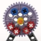
 As part of Splat's To-and-Fro GBC, the mechanism that provides a means to halt the GBC if there is a jam I found to be particularly interesting. RohanBeckett then posed a challenge (half in jest?) to adapt the mechanism to automatically reverse the GBC for a short period of time and then for it to resume normal behaviour. So I decided to take up the challenge and came up with the following. In the video, my hand simulates the case of a GBC mechanism becoming jammed by holding the output axle. Following the "jam" there is a pause, the output axle momentarily reverses, pauses once more before resuming the original rotational direction. This mechanism is in the experimental stage and there is a minor defect. The defect, as shown in this second video, is that the differential continues to turn a very small amount even when there is no jam. The gearing ratios are correct, so I suspect that the rotation is being caused simply by the rotation of the axle. I'm posting this thread for two reasons; 1) to garner possible solutions to address the defect 2) to see whether anyone else has interest to/is able to improve/alter the mechanism. I'd be open to any suggestions as to how the incidental rotation of the differential could be eliminated. I'd also be open to seeing other peoples' interpretations to make a mechanism to achieve a similar result. For convenience, I have made the build instructions (PDF format) and the LDraw file (MPD format) available for download from BrickSafe. There are also a couple of images of the two sides of the build: Regards, David
 -
Sioux.NET on Track presents the Ticket Dispenser Unit (TDU) Two articles about the Lego Dispenser Unit can be found at our blog: https://siouxnetontrack.wordpress.com/2016/09/28/ticket-dispenser-unit-reader/ In this article you can read how tickets are read using a four-color based number system. This article was written before the dispenser part was created, so it is only about the reader part. https://siouxnetontrack.wordpress.com/2016/12/28/ticket-dispenser-unit-complete-version-2017/ In this article you can read about the upgraded version that will be used at Lego World 2017. Click on the following picture to see more pictures: A video of the working TDU 2017 can be found here:
-

[MOC] The Automatic Birthday Crisp Delivery Vehicle (ABCDV)
896gerard posted a topic in LEGO Technic, Mindstorms, Model Team and Scale Modeling
Sometimes, you have annoying things on a birthday party and with this MOC, I tried to solve at least one of them... For higher-quality images, click http://www.brickshel...ry.cgi?f=565441 (The first day, it's never public, which is strange) [edit]: MocPages link: http://www.moc-pages.com/moc.php/431271 for better quality images.. The video explains all trouble and how I solved it: -
Hi folks, It is one of my earlier builds that I want to share with you: an automatic railway crossing. The LDD sketch: The barriers of the crossing are powered by two medium PF motors. I use two PF receivers: one to control the PF motors of the barriers, and one to control the lights. The two PF lights are crosswise connected to the PF receiver. By this means, I am able to get flashing lights and add sound. All of this above is controlled by a Lego Mindstorms NXT and an Hi-Technic HR link (in case you don't know: with the HR link you can translate Mindstorms commands into PF commands). In the video below you can see and hear the result: In the video below you can see the result in a small train layout. A PC application controls the two trains (both having a Mindstorms NXT + HiTechnic sensor to control the train) and also the Mindstorms NXT that controls the railway crossing. Hope you like it. /Hans
-

[MOC] Fully automatic Clock
Gonkius posted a topic in LEGO Technic, Mindstorms, Model Team and Scale Modeling
This is a fully automatic clock that was finished end of 2014. So, why do I call it "fully automatic"? - The clockwork runs as a normal mechanical clock with a pendulum and counterweight. - There is a motor that winds the clock every hour. - The speed of the clock is adjusted once a day using the Mindstorms unit. The speed is adjusted by changing the length of the pendulum. In total, the clock runs for itself without any assistance, and it shows the right time, even if it is build using only LEGO bricks. (Apart from the string to the counterweight) There have been many challenges in this design. My main focus, except the obvious goal to make everything to work, was to make this as compact as possible. The whole clockwork fits inside 14x14x14 studs. I did a short video to show the "action": The two sensors are used for: 1. Stop when the counterweight is fully winded 2. Give feedback from the minute hand rotation back to the Mindstorms unit. The counterweight is made out of 12 train/boat weights and is about 0.68kg. Winding is done through a differential to avoid interruptions during the winding. There are two medium motors inside the clockwork for the winding and adjustment. The Mindstorms unit is hidden in the base behind a hatch: WIP pictures Specially designed differential gear to reduce the friction between the counterweight and clockwork as much as possible. The winding motor rotates the large turntable gear: Clockwork prototype, without any automation: Very first prototype of the escapement: -
Hi all For our project "Fully automated train layout" (more information can be found here: https://siouxnetontrack.wordpress.com/), I have designed an automatic train decoupler. A video of the first test run can be seen here: .For our Lego World 2015 layout, we have adapted the decoupler (expecially more speed) but the basics remain the same: The wagon(s) behind the train are pushed away to overcome the magnetic force of the coupler Loco moves forward (this is needed otherwise the magnetic force pulls back the wagon if it is not too heavy like the one in the picture above) Because our train layout is fully automated, Mindstorms is used for the controls. But the same principle can of course be made using a PF motor and PF receiver. Enjoy. /Hans
-

[WIP] Supercar with automatic transmission
MSc Shobaki posted a topic in LEGO Technic, Mindstorms, Model Team and Scale Modeling
Hello you guys! My name is Ahmed El Shobaki, 25 years old, originally from Palestine, born and raised in Stockholm, Sweden. I've been reading through the topics for a while now in the Technic Mindstorms etc. section which led me to start a project of my own. After being inspired by very famous technic builders, namely Paul Boratko aka Crowkillers, Nathanael aka NK as well as Sheepo, I felt interested in building something extraordinary. Currently, I'm studying to become a MSc. Engineer in Advanced machine design at RIT, Stockholm where I only have some courses left before I get my degree. Enough said about me for now My project is about designing a smooth, great looking car as the fellow builders which previously were mentioned build, but I want it to be multifunctional. So I stated some criterias for the car to feature: Realistic suspension and steering (camber, caster, ackermann, multilink etc.) Front wheel driven by PF PF operated steering of wheels and steering wheel Remote controlled Fully mechanical automatic transmission. Pneumatic controlled doors with onbord compressor and remote controlled valve (open/close) PF Lights Two-seater Last but not least, easy access to batterybox as well as other functions like e.g. openable boot and hood. Three days ago, I learned how to use SR3D and now I'm almost halfway through with my model. I haven't built the model IRL, so the project can be either a real success when I finally build it or a complete failure hahahaha This is due to my regular work in the university where I'm an experienced CAD-designer and design stuff first in CAD before I manufacture something. I will post images of the building process and I hope that you'll like what you'll see. - MSc Shobaki Some WIP images: https://www.dropbox.com/sh/zkvp9a2tj3447os/AACc-ffpXP16P-lY06Y450Hea?m=