Search the Community
Showing results for tags 'power functions'.
Found 368 results
-
Mini RC Tatra 813 - 8x8
Tamas Juhasz posted a topic in LEGO Technic, Mindstorms, Model Team and Scale Modeling
Hello! My newest mini moc is also a Tatra. My goal was to make a 8x8 813 model with realistic Tatra suspension: This was my first moc, which could be build with 1:1 scale from a paper: I always wanted to build a really small Tatra with the wheels from 8842. This wheel has a diameter of 43 mm, so the proportional width is about 11 stud. That's even not enough, too narrow, but I had success with the suspension and drivetrain in 13 stud width. The first and second axle has steering, and all axle is driven and suspended. With U-joint there is no way to build it narrower. I used 3 different shock absorbers. The first axle has harder ones to hold the weight reliable in the front. The steering mechanism only steers directly the left wheels, the right ones are steered by the 9L links: http://www.brickshel...y.cgi?i=5748589 The ground clearance enables 25 mm high obstacles under the truck. Of course it can go through much bigger ones, as can be seen below in the video. The drivetrain is pretty simple Tatra like, with assimmetric left and right side: http://www.brickshel...y.cgi?i=5748587 In the picture it also can be seen that the front 4 wheels are driven with a small 2L thin liftarm to prevent clacking(if it uses pins and pulley). There wasn't problem with that, in every terrain kept the front wheels the correct position. They look like the valve cover of the wheels.( I forgot to take them also in the rear wheels) Maybe from the pictures we can think that the 12 bevel gears can go out in the middle of the axles. They can't. The 2L red axles prevent that (I used strong 12 gears and loose U-joints). The suspension worked well in terrain, this Tatra doesn't carries tons of weight, stronger axles aren't necessary. The wheel travel is about 2 stud or a bit more depending of the axle. Technic inside: http://www.brickshel...y.cgi?i=5748652 The steering M motor is in the front, the driving M motor is in the rear part. The M motor is powerful with 6:1 final ratio. It can be, because the weight is only 761 g. The stability surprised me. In the video can be seen some test. The aesthetics was also important for me, this one isn't a trial truck, more civil version. I had to cut the mudguards to give space for the wheels, and of course it's a bit higher than the real Tatra to have wheel travel. The front grill has a Tatra logo and some covering sticker: The on/off button is in the top of thew vehicle: If you hit the PF connector, the front LED lights will work(video). I didn't want a PF switch, and wanted to try this out. And the video with infos: If somebody needs, I can upload the building instructions. -
UPDATE: see below... _____________________________ I do not know exactly where to put this truck, or in the City or in Technic. Given that, it looks like Lego City vehicle and is in minifig scale, will probably be alright here. As the title says, this is Iveco Eurocargo truck. You can see the original on this link: http://dayerses.com/...urocargo-02.jpg For this MOC I was inspired by M_longer with his Mini PF truck: http://www.eurobrick...showtopic=33204 And what is so interesting on my truck? In particular, that the dimensions are in minifig scale, however it contains a Power Functions components for moving and turning. Here are some photos without PF components: Truck has a cabin 6 studs wide and cargo compartment 7 studs wide. Overall length is 21 studs (6 cabin + 15 cargo compartment). Spacing between front wheels is 5 studs (because each wheel is 1 stud thick), but back wheels have a spacing of only 3 studs (because each wheel is 2 studs thick). On the front wheels there is one tire plugged on each one, on the rear wheels there are two tires on each one. So the rear side of the vehicle looks very realistic. Here is visible the entire length of the truck: Front view: Detail view on the rear wheels: And here are some photos with PF components installed: At the top of the cargo compartment there is visible PF receiver. Maybe a little disturbing, but I had to install it somewhere. The vehicle also has some Technic bricks that are used for more strength. Under the cargo compartment cover there are hiding PF components. You can find there the BB with 6 AAA batteries, receiver and two M motors. Lower motor drives the rear axle to drive the truck forward/backward, upper motor is responsible for turning the front wheels (drive left/right). Above the motors there is the receiver that goes through the cargo compartment cover. On the BB there is a spacer installed, which is also used as an on/off button for BB. Here is a movie: Enjoy. ____________________________ UPDATE The cargo compartment cover is placed on the vehicle and is constructed so that it is consistent with the elevation and longitudinal spacers. Spacers prevent movement of the cargo compartment cover forward/backward and downward. For disclosure of cargo compartment you just lift up the cover. It's that easy. The most disturbing part on a truck are cables. And I do not mean aesthetically, but also spatially. It is difficult to find a suitable place for their implementation. Compared with the vehicle from M_longer: mine has the same basic drive, but turning is resolved differently. I also installed two M motors so that's why there is less space.
-
 On YouTube, CamsPL / Cams posted of his yellow Lego Technic Walking & Turning Biped (W&TB) Mecha model. It uses three Power Functions (PF) Medium motors to walk and turn. More on his Flickr photoset, and on his Brickshelf Gallery (when moderated). He also made the red Walking & Riding Biped (W&RB). which uses four Power Functions M-motors to make it "ride, walk, skate, and turn" : ( ) (Flickr photoset) (Brickshelf Gallery when moderated)
 -

Technic pickup truck + building instructions
Hedgie posted a topic in LEGO Technic, Mindstorms, Model Team and Scale Modeling
Hi all, I have created building instructions for a remotely controlled car and my girlfriend tested them. She says they're really good Although I primarily created the instructions so I could rebuild the model later, I figured it would do no harm to share them here as well. You can download both the LDraw model file and the PDF building instructions. If you have any questions I'll be glad to answer. -
Tall Tower flickr set ~ .lxf file Inspirations: The Westin Bonaventure Hotel Galtier Plaza Nils Hasselmo Hall Until next time!
-
Micro RC truck
Tamas Juhasz posted a topic in LEGO Technic, Mindstorms, Model Team and Scale Modeling
I uploaded my smallest truck few days ago: Folder: http://www.brickshelf.com/cgi-bin/gallery.cgi?f=520763 My purpose was a very small trailer truck with remote control. The PF RC system rquired the trailer, in the tractor truck there is only space for one micromotor and the suspension. Total length is 42 stud, width is 5 stud in the truck, 6 in the trailer. The trailer's height is 10 stud at maximum. One old 71427 motor drives the rear wheel of the truck with universal joint: Then, 6 of the 12 tooth bevel gears make connection with the rear axle: The steering is done with micromotor. There is 4 functions in this moc: 1 driving 2 steering 3 Led lights in the back 4 suspension There is one receiver for the leds, so they(orange and red) can be controlled individually: Except the truck's driven axle, all axle has suspension. Front: http://www.brickshelf.com/cgi-bin/gallery.cgi?i=5733797 Trailer - the red suspension parts are from the city theme, I like these small live axles, they are perfect for here: The most tricky part was the tractor truck of course. Fortunately I have two large red doors from an old set, so I could do the truck with this looking: I know that the wheels are a bit small for this body, but who cares. If we take a look at this( http://www.autospies.com/images/users/cawimmer430/5678_1.jpg ), then it's not so big. The trailer is full with PF parts. From the front part there are: 71427 motor - AAA battery box - two PF receivers - leds. The few metallic silver grill plates cover the receiver's infra parts, so you can't see them, but the communication between them and the remote controller is still good: For the control the 8879 remote control is recommended, as can be seen in this video: Hope you like it. -
How do I use the power functions remote and motor? My emerald night train is built but I cannot get it to work. I can hear the motor running and the lights are on but it is not moving. Please help!
-
Hello, I have just took apart the XL motor to look at some things and see if it was possible to put the XL planetary gear reduction on another motor. The goal is to get more Rpm (@9v) out of the planetary gear reduction by attaching it to another motor. I have setup this tread to document this attempt. I did not want to break the clips off the case so dismantling the XL motor was tough. Currently the motor shaft is a little bigger than the XL motor shaft size. Is there any technical information on the motor that is in the XL.
-

Walking excavator
Zerobricks posted a topic in LEGO Technic, Mindstorms, Model Team and Scale Modeling
After completing the autopump i realized it would be very usefull in a construction equipement. But i wanted to build omething special, unlike the usual classic machines. This is why I chose a walking excavator type of a vehicle. To lift and tilt its legs I used pneumatics, because they are better in routing tubes over the complex joints on which the machine rests. For operation of the arm I chose LA's due to their ability to accurately move loads with little jerking. So here's the excavator nice and tightly folded. The legs are spread and the boom begins to lift: The four legs are than lowered therebye lifting the whole excavator up some 10 cm: As you can see each of the tracks has its own M motor, the total number of motors being 11, all M type: Feeding on some bricks: And spewing them out: The underside of the bottom showing the two autopmups used to lower and spread the legs: And the video of excavator in action: All in all I am quite pleased with the model, especially the pneumatic side of it. Its really fun to play with it, lift it up and dig out the bricks. There are some things bothering me though: The legs bend too much sideways The speed of the superstructure is a bit fast Pneumatics are unstable unless in maximum lowest or highest position Long wheel base makes skid steering hard What'ya all think? -
Well I thought I would post the results of my efforts today, nothing special but my son decided to get the monster fighters ghost train set with some of his Christmas money, and after he finished building it this morning he instantly said to me "can we add power functions daddy?" So here is the result, the other side isn't complete yet as I didn't have enough parts, I also had to raise the front by one flat so that the flangeless driving wheel didn't derail the train on the exit from bends, can't find a better solution for that yet! Let me know what you think! Cheers, Dave
-

Dual PF Battery Box Power Tutorial
Boxerlego posted a topic in LEGO Technic, Mindstorms, Model Team and Scale Modeling
Hello fellow LEGO enthusiasts, I am Boxerlego. I want to Introduce myself along with this technical tutorial on a dual PF battery box setup. This no hack, this is science and knowledge along with real experience with each of the devices and their respective function. I will explain thoroughly why this works and why it is absolutely safe for the IR receivers and motors. First thing is some battery safety. It is very Important that you are using the same type of batteries for both the battery boxes. Never connect up two dissimilar types of batteries together. Connecting two 9 volt battery boxes together is very safe to do, nothing is going to "burn up" on you when connected together as mentioned. Each of the electrical connections are made entirely out of Lego and combines both style of electrical connections to get working. There will be a simple alternative method to hook up the dual battery setup only requiring the PF extension wires. Moving to motors. I suggest on using the PF L or XL motor or a 5292 buggy motor with this battery setup. This is not for powering servo motors or micro motors old the old 9V motors. It is important to know that there is a resettable fuse protecting each of the suggested motors along with the battery boxes and IR receivers. I do not recommend putting the voltage over 16 volts on the Lego motors. Most motors typically can handle 12 volts. There are many things to understand about the electrical function that is at work here. I have created Two simple pictures detailing the two electrical functions and how they both end up at 18 volts. I will start with the #2 picture. The #2 picture represents when the battery boxes are connected together in series providing you with a +18 volt power. Understand that all the electrical wires are connected together to establish a electrical path, directly connecting both the battery boxes together to function as one combined battery box for the motor. The #1 picture represents using the dual IR receiver connection and how you can safely create a voltage gap between a positive(+) and a negative(-). Neither of the IR receivers is ever exposed to the same load the motor is receiving. Instead, each of the IR receivers is carrying the load of their perspective battery box. This voltage gap creates the theoretical 18 volt supply for the motor. You will need 2x 9V PF battery box 2x IR receiver 3x PF extension wire 2x 9V Motor Wire 1x IR switch remote 1x of the suggested motors I will start with the two 9V motor wires... Connect the two 9V motor wires on a 2x6 plate like so... Look carefully at the short wire and how the electrical contacts are Aline... Connect two of the PF extension wires together with a 2x2 plate... Put a red and blue 1x2 plate on to the PF extension wires... Connect the PF extension wire setup to the 9V motor wire setup... This is what is should look like... Hook up your battery boxes with the IR receivers... (Important Note: If you are doing this with NO IR receivers, the switches on the battery boxes should be turned on opposite directions of each other when connected with the motor.) Make sure both IR receivers are set on the same channel... Connect the blue PF cable to the blue terminal on one of the IR receiver And then On the other IR receiver connect the red PF cable to the red terminal... (Note: If your doing this with out the IR receivers. Connect each of the cable to a separate battery box. Remember to switch the battery boxes on in opposite directions) Connect both the switches on the IR remote together as one and set on the same channel as the two IR receivers... It is very Important that the two polarity switches on the IR remote are switched opposite of each other... The 9V motor wire is where you will connect your motor to... When connecting up a PF motor simply connect the PF extension wire on top of the 9V motor wire and the PF motor on top of that and you ready to go. Here is a test to see if this increased voltage will cause any kind of damage to the motor when pulling up this 7.5 lb weight. The first test shows the safety fuse in action. Next I put the M motor to the 16 volt power pull test. The final video is a demonstration that no matter how big or small the battery is, a motor will behave the same as long the volts are the same. Edit: The information in this tutorial will be improved upon periodically. -
 Is it possible to control PF motors using a mobile phone with appropriate application? Is there already some solution? I have found, that there are some audio jack based IR transmitters (like this) that can turn even a mobile without IR port into a IR controller. PF receivers operate at 38kHz. Principle of these audio based IR transmitters is simple - it is enough to play a proper audio file. Application should be able to generate proper audio signals based on the controls touched by the user on the mobile screen. From this point of view also the application is quite simple, once proper signals are known (in extreme case they can be recorded from the original PF transmitter). Does it make sense? Will it work? Or is there a better solution? That audio jack based transmitter contains actually only two IR diodes and some resistor to protect them. From this point of view, they are highly overpriced.
 -

Makorol's creations
Makorol posted a topic in LEGO Technic, Mindstorms, Model Team and Scale Modeling
Hi everyone. I'm new to eurobricks and before the presentation of my new MOC that is going to be finished in weeks, i want to show you some of my previous models. I think that describing all of the creations doesn't make sense, so I will show you only my best (In my opinion) MOCs: My latest creation - CAT 963D crawler loader. Very simple construction, just 4 PF M motors, 2 IR receivers, rechargeable battery box, some gears and stuff. But I really like this model, it works smoothly and it's a big fun playing with it. (Image is a link to the gallery) _________________________________________________________ Another model, Liebherr HS-855 dragline excavator. Big model, difficult to build. But it worked quite good. It was hard to learn how to dig with it :) It had 7 motors inside, 2 battery boxes and 3 IR receivers. Only cabin lifting wasn't remote controlled. (Image is a link to the gallery) _____________________________________________________________ Another yellow machine :) Liebherr LTM 1050 mobile crane. My favourite one. The mechanics of the model were very complicated, but as I remember, everything worked quite good. 7 PF motors, 3 IR receivers, battery box, some pneumatic stuff. (Image is a link to the gallery) ______________________________________________________________ In my gallery there are more models, but describing all of them here doesn't make sense. So, here is my gallery: Brickshelf Flickr And the YouTube channel: Youtube (make sure to subscribe to be up-to-date with my new videos ) If you have any questions - feel free to ask! PS. Is it posible to embed a YT video? -

Odd/weird sound from a PF L Motor
jacobkristensen posted a topic in LEGO Technic, Mindstorms, Model Team and Scale Modeling
Hi Guys A few days I got my self a 9398 set for only 989dkk(133 euros) in Bilka(a major supermarkedet store in DK). Anyway after I got home, I didn't play with the motors as I normaly would mainly because I simply wanted to build the 4x4 offroader. But after I had assembled the 2/3 of the set, I got some batteries in it, and fired it up. Thats when I got a bit annoyed/shocked/scared to notices that the front motor sounds much louder than the other motor. It some kind of of squick sound that, aint healty when compared to the other. Have anybody else notices different noises from the PF L Motor? -

MOD: 4511 & 7740 Power Functions AA Battery Box (Orange Switch)
Luke_likes_Lego posted a topic in LEGO Train Tech
Hi Everyone, Many PF users would be familiar with this battery box: Pro's : Takes AA batteries (6xAA should last longer than 6xAAA) Cheap (about 1/3 to 1/4 of the price of the AAA 8x4x4 version) I seem to have lots of spares Cons: Awkward shape Too large to fit in the 'compartment' section of most trains Not many studs Anyway, as I had some of these battery boxes sitting around, and I wanted to convert my: 7740 12V to PF; and 4511 9V to PF using the 9V motor with PF attachment, I have made the following attempts and shown the approach below with some pictures. Please take note.... I'm not suggesting this is better or even equivalent to using the AAA or rechargeable battery box...... ....just something I have done to make use of my AA battery boxes . Hopefully it might be useful to someone !! 4511: World City High Speed Train New Carriage: Tha AA battery box revealed: Held in place by four pins in each end (and gravity): And the flawless (get it? ) reason this battery fits : 7740: Inter-City Passenger Train I'm not as pleased with the look of this one - which is a bit over utilitarian....but hey...on a practical level it does the job !! Roof is modified in the front for the IR receiver and in the rear for the protrusion of the battery: The switch is integrated into the pantograph, which slides into the three different positions (camera also shows my 1x6 black plate in need of a good clean ): Removal is easy enough: From the rear: All the best. Please feel free to fire any questions at me. I have the lights working in the 4511 and my next project is to do the equivalent in the 7740. Cheers LLL -

Peterbilt 379 & CAT C15
Sheepo posted a topic in LEGO Technic, Mindstorms, Model Team and Scale Modeling
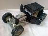
After many delay, now I present my new big MOC, It was in LFW in Skaerbaek. Since I was a child I has been a fan of big trucks, and specially of American style trucks(in Spain is strange to see trucks with long noise). For this MOC I have chosen one of the most charismatic and representative models of these trucks: a Peterbilt 379. Also I have endeavored to put a version of CAT C15 engine (I'm also a fan of the brand CAT). This MOC is made in a 1/10.2 scale, giving a final size of 31 studs width, 99 length and 40 high. Here you can see some pictures taken in Skaerbaek where you can appreciate the size, there are: this Pete, the Crow's Vampire GT(scale 1:10 too...), the Nathaniel's Supercar and my Veyron. The total weight is 5.5kg, and has been one of the main problems I've had. Front axles deforms and look like the wheels has huge camber angle. This is a esthetic defect which I hate, but it has not solution if I want to keep all functions and therefore the weight of the truck. I will try to fix it comming soon. The electric system is huge, and it has: - 2 AA PF battery boxes - 4 PF IR recievers - 5 PF XL motors - 5 PF M motors - 1 PF switch - 3 PF large extension wires (50cm) Probably, the most “wanted” picture for Lego Technic followers: CAT C15 Engine Under the hood you can find a replica of the CAT C15 engine, with its 6-cylinder in line. The engine doesn't have the sides covered to appreciate that the cylinders are located in the same order as the real engine, with 120 ° intervals between them. Getting those 120 º between cylinders was very complicated but I thought it was necessary to be more faithful to the original. The engine also has a motor M to rotate it, which is connected directly to a battery. Between the engine and the M motor there are a differential, which is also connected to the drive motors, so that the engine is always at idling, but when you starts the drive motors the C15 accelerate adding both speeds. The rotation speeds grow up from 250 rpm up to 700 rpm aprox. Pneumatic system After almost 10 years without using pneumatics in any of my MOCs, I decided this was the perfect model to use it. The pneumatic system the truck runs along the complete truck, mainly controlling the suspension and brakes on all axles. The pneumatic system is composed mainly: - 2 Small pumps (6L) - 1 Large pump (for emergencies). - 2 Air tanks - 7 Small cylinders - 8 Large cylinders - 7 Valves - 1 Manometer (LEGO part n.64065) - 22 T connectors - And about 5 meters of pneumatic tube in 3 colors: blue, black and light gray. All pneumatic control is located on the right side of the truck inside the fuel tank. Also in the cab, between the seats, there is a manometer to measure the system pressure, it is very useful to know how much air have you at any moment. Axles As the real truck it has live axles. Both rear axles are driven without differential between them. In each axle between the differential and the wheel the axls has gear ratio 12/20 to reduce necessary torque in the differential and protect bevel gears. The front axles uses the same steering system as the real Pete, of course the steering wheel turns too, also it turns 4 laps, again as the real Pete - Suspension The suspension is fully pneumatic in all axes, and it doesn't use any spring to help. The front axle has 4 big cylinder and each rear axle 2. - Brakes The brakes as the real truck are drum brakes, there are a drum on each side of each axle, all of them controlled by a small pneumatic cylinder. The control of these pistons are made through two valves, one for the front axle and one for the rear axles. For normal braking the brakes operate all at the same time, but only while you are keeping push the brakes botton. But you have also parking brake mode, if you push the brakes botton in the opposite direction only rear brakes works, and they will not disabled if you stop pressing botton. To remove the parking brake you only need use the normal brakes. - Auxiliar output Behind the cabin there is an auxiliar pneumatic output(blue connector), where you can connect anything you want. The valve to activate it is located before the rear-right wheel Transmission The transmission is the biggest mechanism of the truck, and it has an approximate size of 25x7x45 studs. It uses 4 XL motors for drive. The transmission has 18+2R speeds(this is true, is not a joke...). The transmission is divided in two parts: the main gearbox with 9+R speeds with automatic clutch(this gearbox is based on the LR Defender), and a transfer case with 2 speed (H and L) Joint both gearboxes the result is this: RL-1:0.261 RH-1:0.29 1L (1) - 1:0.324 1H (2) - 1:0.36 2L (3) - 1:0.432 2H (4) - 1:0.48 3L (5) - 1:0.54 3H (6) - 1:0.6 4L (7) - 1:0.72 4H (8) - 1:0.8 5L (9) - 1:0.9 5H (10) - 1:1 6L (11) - 1:1.2 6H (12) - 1:1.33 7L (13) - 1: 1.5 7H (14) - 1:1.67 8L (15) - 1:2 8H (16) - 1:2.22 9L (17) - 1:2.5 9H (18) - 1:2.78 Auxiliar electric output As I said before, the truck has an auxiliar pneumatic output, but also it has an auxiliar electric output too. There you can connect anything you want, and control it with the remote controller. To avoid leaving this connetor without any use I have added a fifth wheel(trailer connector). - Fifth wheel Note: right now I don't have intention to do a complete trailer. It is very simple and effective. The kingpin diameter is 1 stud. Finally as always, you can see a complete video with all features showed: For more detalied information visit sheepo.es I hope you like it!! -
8x8 Trial Truck, The Pumpkinator!
Saberwing40k posted a topic in LEGO Technic, Mindstorms, Model Team and Scale Modeling
Well, here we are. This is my latest truck, and I call it, due to the color, the Pumpkinator. All eight wheels are driven, and the front four steer. Drive is via one XL motor, geared down roughly nine to one. The axles are loosley inspired by a design from Zblj, and are very tough, except for the third axle, which has grinding gears. Suspension travel is not a whole lot, but it does the job, and is fairly compact. This truck is actually a project I was making for school, and was originally going to be an Oshkosh PLS truck, although this did not pan out due to time constraints. I built this thing in only 6 hours! Anyway, I got a good grade, which was a good thing . I may or may not make instructions, and a video. Would anybody want either of those? Anyway, on to the pictures, and some additional details. The side views, showing the roll cage (made out of 32l axles), the suboptimal location of the battery boxes, and the spare tires. The underside view, showing the drive axles, the drive motor, and the suspension setup, which is 4 link. A closeup of the rear 2 axles, showing the mechanics. The connection to the third axle is rather weak, and the gearing skips. However, it only does this on extreme slopes. The front axles. This was the hardest part to make. The steering motor. The cabin has no interior, as it was literally an eleventh hour addition. The connection from the front motor to the steering axle. The steering clutch sometimes balks, so that's goin to be redesigned. The top of the suspension, which is mostly identical for all axles. Front view with the lights on. Rear view with the lights on. The very front, but it's not actually based on any Mercedes... Suspension travel. Upper limits. Enjoy, and keep on building! -
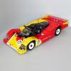
Scuderia Ferrari Transporter (Power Functions)
Ape Fight posted a topic in LEGO Technic, Mindstorms, Model Team and Scale Modeling
Thanks to those on this site who helped answer my queries about Power Functions : ) I've now finished the FIAT 682/RN2 Bartoletti. It's currently running one battery box powering 2 XLs and 1 Medium through 1 IR Receiver, but when it gets some race cars the whole setup will be doubled (except the steering the motor). A couple of pics are below - more on MOCpages at this address: http://www.mocpages.com/moc.php/278673 Comments welcomed : )