Search the Community
Showing results for tags 'nxt'.
Found 70 results
-
 Teaser: Introduction The article describes the experience of using the Lego Mindstorms EV3 set for creating a robot prototype with software and manual control via Robot Control Meta Language (RCML). Next, we will discuss the following key points: Assembly of the robot prototype from the Lego Mindstorms EV3 set. Quick RCML installation and configuration for Windows. Robot software control based on EV3 controller. Manual control of the robot peripherals using a keyboard and a gamepad. Jumping a little ahead, I will add that for implementing control over a Lego robot via a keyboard, one will have to create a program containing only 3 lines of code. More information about it is available under the cut. Step 1 First, the Lego Mindstorms EV3 set was used for creating a prototype robot to be used for programming and manual piloting. The robot's design is similar to that of a truck chassis. Two motors installed on the frame have one common rotation axis connected to the rear wheels via a gearbox. The gearbox converts the torque by increasing the angular speed of the rear axle. The steering system is assembled on the base of a bevel gear speed reducer. Step 2 The next step is RCML preparation for working with the Lego Mindstorms EV3 set. Download the archives with executable files and library files rcml_build_1.0.6.zip and rcml_modules_build_1.0.6.zip. The following describes the quick start procedure for ensuring interaction between RCML and the Lego robot controlled by an EV3 controller. Content directory after extracting the archives Next, one has to create configuration file config.ini to be placed in the same directory. To implement control over the EV3 controller via a keyboard and a gamepad, connect modules lego_ev3, keyboard and gamepad. Listing of configuration file config.ini for RCML [robot_modules] module = lego_ev3 [control_modules] module = keyboard module = gamepad Next, the EV3 controller should be paired to the adapter. The instruction for pairing an EV3 controller to a Bluetooth adapter: The reference guide contains an example of pairing a Lego Ev3 controller to a PC running under Windows 7 operating system. Next, go to the Ev3 controller settings and select menu item "Bluetooth". You should make sure that you have set the configuration settings. “Visibility” and” Bluetooth” should be ticked. Go to "Control Panel", select "Devices and Printers", and "Bluetooth Devices". Click on the "Add device" button. A window with available Bluetooth devices will open. Select "EV3" device and click "Next". Dialog box "Connect?" will be displayed on the EV3's screen. Check as appropriate and confirm by pressing the center key. Next, the "PASSKEY" dialog will be displayed, enter digits "1234", and confirm the key phrase for pairing the devices by pressing the center key at the position with the tick image. In the pairing wizard of the device, a form for devices pairing key will appear. Enter "1234" and press "Next". A window with confirmation of successful device connection will appear. Press the "Close" key. At the PC, return to "Control Panel", select "Devices and Printers", and "Bluetooth Devices". The paired device will be displayed in the list of available devices. By double clicking, go to “EV3” connection properties. Next, go to the "Hardware" tab. By double clicking, go to the connection properties of the "Standard Serial over Bluetooth link". The COM port index specified in the properties should be used in the config.ini configuration file of the lego_ev3 module. The example shows Bluetooth connection properties of a Lego EV3 controller with the use of a standard serial port COM14. Further module configuration is limited to specifying the address of the COM port used for communication with the Lego robot in the configuration file of the lego_ev3 module. Listing of configuration file config.ini for the lego_ev3 module [connections] connection = COM14 [options] dynamic_connection = 0 Now configure the keyboard module. The module is located in the control_modules directory, then keyboard. Create configuration file config.ini next to the keyboard_module.dll file. Before creating a configuration file, specify the actions to be performed by pressing keys. The keyboard module allows using keys with a certain numeric code. The table of virtual key codes is available here. As an example, I will use the following key press events: The up/down buttons are used to rotate the rear wheels motor forward/backward. The left/right arrows turn the wheels left/right The configuration file of the keyboard module describes which axes are available for the programmer to implement interaction with the robot in the manual mode. Thus, in the example we've got two control groups - these are keyboard axes. To add a new axis, stick to the following rules of axes description. Rules for describing axes for the keyboard module. 1. In case of adding a new axis, add axis name property to section [mapped_axis] and set it equal to the value of the keyboard key in HEX format; there may be several keyboard button values for one axis. In general, an entry in the [mapped_axis] section will look as follows: axis_name = keyboard_button_value_in_HEX_format 2. You should set the maximum and the minimum values that the axis may take. To do so, add to the config.ini configuration file a section named as the name of the axis, and set the upper_value and lower_value properties for passing the values of the axis' maximum and minimum. In general, the section looks as follows: [axis_name] upper_value = the_max_axis_value lower_value = the_min_axis_value 3. Next, you should determine what value the axis will have after a previously defined button on the keyboard is pressed. The values are defined by creating a section with the name consisting of the axis name and the value of keyboard button in Hex format, separated by underscores. To set the default (not pressed) and pressed state values, unpressed_value and pressed_value are used, where the values are passed. In general, the section in this case will look as follows: [axis_name_keyboard_button_value_in_HEX_format] pressed_value = axis_value_with_pressed_button unpressed_value = axis_value_with_released_button To implement the control over the robot prototype, a configuration file of the keyboard module has been created, which includes the "go" and "rotate" axes. The "go" axis is used to indicate the direction of robot movement. When the “up arrow” button is pressed, the axis is set to 100, and when the “down arrow” button is pressed, the axis is set to -50. The rotate axis is used for setting the front wheels turn angle. When the "left arrow" button is pressed, the axis is set to -5, and when the "right arrow" button is pressed, the axis is set to 5. Listing of configuration file config.ini for the keyboard module. [mapped_axis] go = 0x26 go = 0x28 rotate = 0x25 rotate = 0x27 [go] upper_value = -100 lower_value = 100 [rotate] upper_value = -100 lower_value = 100 [go_0x26] pressed_value = 100 unpressed_value = 0 [go_0x28] pressed_value = -50 unpressed_value = 0 [rotate_0x25] pressed_value = -5 unpressed_value = 0 [rotate_0x27] pressed_value = 5 unpressed_value = 0 Next, for control implementation using a gamepad, configure the gamepad. Configuring the module includes creating configuration file config.ini next to gamepad_module.dll in the control_modules directory, followed by gamepad. Listing of configuration file config.ini for the gamepad module. [axis] Exit = 9 B1 = 1 B2 = 2 B3 = 3 B4 = 4 L1 = 7 L2 = 5 R1 = 8 R2 = 6 start = 10 T1 = 11 T2 = 12 RTUD = 13 RTLR = 16 LTUD = 15 LTLR = 14 arrowsUD = 17 arrowsLR = 18 [b1] upper_value = 1 lower_value = 0 [b2] upper_value = 1 lower_value = 0 [b3] upper_value = 1 lower_value = 0 [b4] upper_value = 1 lower_value = 0 [L1] upper_value = 1 lower_value = 0 [L2] upper_value = 1 lower_value = 0 [R1] upper_value = 1 lower_value = 0 [R2] upper_value = 1 lower_value = 0 [start] upper_value = 1 lower_value = 0 [T1] upper_value = 1 lower_value = 0 [T2] upper_value = 1 lower_value = 0 [RTUD] upper_value = 0 lower_value = 65535 [RTLR] upper_value = 0 lower_value = 65535 [LTUD] upper_value = 0 lower_value = 65535 [LTLR] upper_value = 0 lower_value = 65535 [arrowsUD] upper_value = 1 lower_value = -1 [arrowsLR] upper_value = 1 lower_value = -1 Step 3 The next step is writing a program in the RCML language. At the root of the created directory, create the program file. The name and extension of the program file may be anything, however, Cyrillic characters are to be avoided. In the example, the filename is hello.rcml. For the lego_ev3 module, the robot redundancy program code looks like: @tr = robot_lego_ev3; The lego_ev3 module connection page contains description of the majority of the features supported by the controller. As a test example, a program for automatic robot drifting has been created. The algorithm of the program is as follows: function main() { @tr = robot_lego_ev3; //Reservation robot @tr->setTrackVehicle("B","C",0,0); //Installing the engine synchronization @tr->motorMoveTo("D",100,0,0); system.sleep(500); @tr->trackVehicleForward(-100); system.sleep(1000); @tr->motorMoveTo("D",50,-50,0); system.sleep(4000); @tr->motorMoveTo("D",50,50,0); system.sleep(4000); @tr->trackVehicleOff(); system.sleep(1000); } After reserving the first available robot, two motors are paired for further operation as one. After that, the robot starts drifting. Program description of robot actions makes it possible to precisely set front wheels turn angles and rear wheels rotation speed. Using this method allows achieving the results that are difficult to replicate by manual piloting from a keyboard or a gamepad. The program is compiled in the windows command line. First, navigate to the new directory with the rcml_compiler.exe and rcml_intepreter.exe executables. Then enter the following commands. The command for compiling the hello.rcml file: rcml_compiler.exe hello.rcml hello.rcml.pc The result of compilation is a new hello.rcml.pc file in the created directory. Now make sure the EV3 controller is enabled, and paired to the Bluetooth adapter. A gamepad should be connected to the PC. After that, run the program file execution command: rcml_intepreter.exe hello.rcml A video showing the robot motion program is located below this article. Step 4 The next step is controlling the robot manually, using a keyboard. The following describes the process of software pairing of robot motors to the keyboard. Keyboard can be used for controlling any motor of the robot. Within the framework of the example, control over the following mechanisms has been implemented: Front wheels turn angle, Direction of rear wheels rotation. The algorithm of the program is as follows: function main() { @tr = robot_lego_ev3; @tr->setTrackVehicle("B","C",0,0); system.hand_control(@tr,"keyboard", "straight","go", "speedMotorD","rotate"); } Then the program should be compiled and executed. The result of manual controlling a Lego robot via a keyboard is shown in the video at the bottom of the page. Step 5 In addition to the keypad module, the gamepad module is available, which makes it possible to manipulate the robot using the gamepad. For implementing control over the robot via a gamepad, one should describe at the program level what axes of the robot will be set to the values of the gamepad axes. The algorithm of the program is as follows: function main() { @tr = robot_lego_ev3; @tr->setTrackVehicle("B","C",0,0); system.hand_control(@tr,"gamepad", "straight"," RTUD", "speedMotorD"," RTLR"); } Then recompile the program and execute it. Below is the result of manual control over a Lego robot via a gamepad, and all previously connected methods: Control Lego Ev3 by using RCML The article briefly shows only certain RCML features. A more detailed description is available in the reference guide.
 -

Floor-roving autonomous robot
technical posted a topic in LEGO Technic, Mindstorms, Model Team and Scale Modeling
Hi all. Here's a brief video of the EV3 floor roving robot I've been working on for the past few days. It's pretty crude but can go a long time without getting stuck. It makes use of one distance scanner in three positions by using a clutched IR sensor, has two bumper sensors that are padded by shock absorbing springs to reduce impact on the touch sensors. Behind the bumper is mounted a color sensor on the front that is used to measure near distance and ambient light. It appears to flash because it's rapidly switching between measuring these two things, With this sensor it can detect objects near to the ground that the main sensor peers over, and also back out of shadows so it doesn't get under furniture. Working on the software has been the long part as there is much debugging to do and each test run can take a long time depending on what I'm trying to improve. It makes decisions based on distances to its surroundings on three sides, so if it senses it's coming up on something in front of it, or a bumper strike is detected, it will choose to turn left or right depending on which direction is more open. -
I made a printer
technical posted a topic in LEGO Technic, Mindstorms, Model Team and Scale Modeling
This is an early proof of concept before rebuilding it completely: Running down the pen: I built this printer LEGO parts. It prints pretty well with markers. It prints in dot-matrix and line modes. I did this with an unmodified EV3. Some of the work was creating huge binary files to print from. Video: -

LEGO Education site has NXT Rechargeable Batterys on sale
djm posted a topic in Buy, Sell, Trade and Finds
Should anyone be interested, the NXT Rechargeable battery is on sale for US$39.97 at the LEGO Education site. Sadly, I understand they will only ship to addresses in the US as they expect non-US customers to source parts from the LEGO designated redistributors in other countries. So in my case as I live in New Zealand, I'm out of luck but at least it is an opportunity for those members who live in the US to consider if this offer is worthwhile. Regards, David -
 At our Youtube channel, you'll find a video of our fully automated train layout. It will be displayed on Lego World Utrecht 2015 from October 25 (Sunday) until October 27 (Tuesday). The video shows the layout in our test room. The train layout contains eight EV3 bricks and one NXT brick to control all the Lego objects. The layout is controlled by a PC application (Microsoft.NET) that has been written by our team. Enjoy the video and maybe we'll meet in Utrecht. /Hans
 -
Background With some colleagues of mine, I am working on a fully automated train layout. You can read more about this at our blog: siouxnetontrack.wordpress.com. The layout is always demonstrated on Lego World in Utrecht. We gave a demo at another event, as can be seen on the following Youtube video. One of the items I have been working on, is the Candy Rotation Stock. I made a working version, as can be seen on the next video: Redesign of the Candy Rotation Stock After building the final version of the Candy Rotation Stock, I transported the object to our office to integrate it with the other parts of the track. I found out that the CRS was not robust enough and it took some time before it worked again. Although the concept works, it was not good enough to run for a couple of minutes without problems. And I needed it to work for four days at Lego World! So I took the difficult decision to redesign it. In this thread you can follow the progress. The redesign will be based on the conveyor belt that I found on Youtube (user ssugawara1955): And this is my proof of concept: I have ordered some extra parts to make a complete square and two switch points: one switch point that will lead to the Crane Pickup location and one switch point where new containers can be inserted to the rotation stock. Some more photos of the progress can be viewed on flickr: https://flic.kr/s/aHsk8h6MAc . Enjoy. /Hans
-

[WIP] Supra Yacht - NXT boat
syclone posted a topic in LEGO Technic, Mindstorms, Model Team and Scale Modeling
Good day everybody and let's continue with the boat mania!!! Today I would like to post my experimental NXT project- The Supra Yacht. It uses two Nxt motors for propulsion , but I disn't tested the propulsion system yet. It is built on top of two 1l plastic water bottles , and all electronics are on top.Because every NXT component is on the rear of the boat I built a long mast on the front for maintain the balance. The mast is connected to one Nxt motor. Here's the video: -
I turned on my NXT the other day. It went pop and smoke appeared under the LCD panel. I opened her up and found the 2200 uF capacitor looked like it blew out some material. There is a hole around one of the leads. I tried testing it with a multimeter and I don't see the resistance changing over time like the other capacitors. When I turned on the NXT again, the LCD displays random moving lines. Has anyone experienced a similar problem with their NXT? Is it repairable? LEGO NXT Repair? by dr_spock_888, on Flickr LEGO NXT Repair? by dr_spock_888, on Flickr
-
Communication between NXT and EV3 brick
Hanso posted a topic in LEGO Technic, Mindstorms, Model Team and Scale Modeling
Lego doesn't support a message protocol that is interchangeable between the NXT and EV3 brick. To overcome that problem, I have written a small program in C# to make the translation between the two different bricks. It works fine, but you always need a PC in between. At our blog (see https://siouxnetontr...pc-application/), I have written an article with a completely different solution, namely a 'motor communication protocol'. Enjoy. /Hans -

LEGO MINDSTORMS : The BEAST
Burf2000 posted a topic in LEGO Technic, Mindstorms, Model Team and Scale Modeling
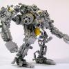
So, this has been in my garage for a couple of years and was supposed to be a mega segway, sadly LEGO MINDSTORMS motors are not powerful enough however 24 of them will move someone. First working demo of it, 24 NXT motors, 8 NXT's pure overkill -

The original idea for the EV3 and NXT
cawlar posted a topic in LEGO Technic, Mindstorms, Model Team and Scale Modeling
Hello, I need advice for individual projects.I have done some work on my channel. Can you review? Waiting for your comments. Good work. https://www.youtube....m3IuBvcPALsXwGQ -
Help with the NXT 2.0 speaker
syclone posted a topic in LEGO Technic, Mindstorms, Model Team and Scale Modeling
Several time ago I had problems with the NXT's speaker. It looks like if the speaker has corrosionrust or something like that.Is there any cheap repairs? I will post photos later. It doesn't produces the standard sounds like turning on or click and the sound files from all the programs are also in silence. (the programs work well) -
 Just learned about this tiny Intel Compute Stick Wondering if it might be practical for use with LEGO Wedo, Minstorms NXT and EV3 BTW how are LEGO Train configured. Does it need a computer?
 -

[MOC] 6 Feet Tall Ball Machine
Purple Geek posted a topic in LEGO Technic, Mindstorms, Model Team and Scale Modeling
Back in 2013, I built and posted about my first NXT ball machine (you can view the original post at http://www.eurobrick...topic=87788&hl= if you are interested). While that machine worked, I learned a lot while building it, so I wanted to create an entirely new machine that incorporated what I learned. I also wanted to make it bigger. Now, in 2015, I have completed my second NXT ball machine. This one is almost 6 feet tall, and over 7 feet wide. The longest span is over 4 feet. It uses simpler lift mechanisms that are more reliable (though they do still jam occasionally -- I have an idea about how to fix that which I am planning to incorporate if I ever build a third one). This machine is also much less sensitive to how level the surface is that it is sitting on. As a result, this machine is a lot nicer to set up and display at a show. It is also much more open, giving people a better view of the balls as they move through the machine. Here's a YouTube video showing the machine in action: There are two possible paths through the machine. The path splits at the top of the left tower with some balls following the gray track that crosses the width of the machine several times. The other half of the balls follow the silver track that spirals down the left tower. Let me know what you think! Ben -

NXT Artificial Intelligence
nerdsforprez posted a topic in LEGO Technic, Mindstorms, Model Team and Scale Modeling
Interesting article on LEGO NXT Mindstorms. CNN News.... good publicity for LEGO!! http://www.cnn.com/2015/01/21/tech/mci-lego-worm/index.html -

Trouble with nxt programming
KDM posted a topic in LEGO Technic, Mindstorms, Model Team and Scale Modeling
I'm a beginner at nxt programming. I built a train drawbridge for my lego city. I thought, I would try and use the nxt technology to make the bridge go up and down as the train crossed over the bridge. I put a pressure switch at each end of the bridge. One to tell the bridge to go up and one to tell the bridge to go down. It seems so simple but has become so frustrating. If train comes from one direction each time no problem. But if the train comes from the other direction the commands get confused. I did two series of commands, each by themselves work just fine. If I put them together, since I'm using the same switches, the program gets confused. I hope someone can help me with my problem. -

Mindstorms NXT Bluetooth
sjim posted a topic in LEGO Technic, Mindstorms, Model Team and Scale Modeling
I am trying to make my Mindstorms NXT communicate with an Arduino board. The final project will be a warehouse robot that checks the colour of the contents on a pallet and stores it on a shelf. You can then order a number of pallets in different colours and the robot will get the order on a first-in-first-out basis. The inventory will be kept on the Arduino board along with the ordering interface and the Mindstorms will do the colour checking. New pallet operation: (NXT) Senses the pallet (NXT) Checks colour (NXT -> Arduino) Notifies the Arduino of a new arrival and its colour (Arduino) Finds a suitable location (Arduino -> NXT) Notifies the NXT of column and row (NXT) Puts the pallet in place (NXT -> Arduino) Sends an ok message (Arduino) Updates inventory Order operation: (Arduino) User creates order (Arduino) Checks which pallets to use (Arduino -> NXT) Requests NXT to get pallet (NXT) Delivers pallet (NXT -> Arduino) Sends ok message Step 3-5 is repeated for every pallet in the order (Arduino) Updates inventory What I can do at the moment: Connect the two manually Send single characters from the NXT to the Arduino What I would need input on: Sending information from the Arduino to the NXT At the moment the two units seems out of sync in some ways. The information sent from the NXT to the Arduino is sometimes picked up and sometimes not. I an guessing this has something to do with the Wait block and the delay() function. I am using the blocks for sending and receiving messages on the NXT and I am using Serial.write() and Serial.read() on the Arduino. The bluetooth module is an HC-06 ( http://www.kjell.com/sortiment/el/elektronik/mikrokontroller/arduino/bluetooth-transceiver-p87942 ) and I am using an Arduino Uno. I have found some information when searching, but many are specific to an alternative NXT language. -

Lego hardware developer kit from 2007 year
Zmei_gorini4 posted a topic in LEGO Technic, Mindstorms, Model Team and Scale Modeling
Hello everyone. Who can help me get a set of hardware developer kit (schemas) for Lego NXT which was released in 2007 (8547) and was produced until release the EV3 I have found only versions before 2007 (9797) thanks -

How would you detect poles with a Lego NXT?
Crackass posted a topic in LEGO Technic, Mindstorms, Model Team and Scale Modeling
So basically I am doing the sumobot challenge where you have to build a robot that has a max length and width of 20 cm each. The arena of the competition is a hexagon with white borders and has 6 poles. The rules and everything is online and is pretty self-explanatory and we are also allowed to have 1 extra sensor than what is in a standard nxt set which is 1 of every sensor in case you were wondering (so we could have 2 light sensors instead of 1). I was wondering how we would detect the poles and and avoid them without interfering with the actual pushing off other people (so not as simple as a touch sensor in the front since other bots would push that too. Someone told me there is multiple ways to do it. I don't really know any efficient ones. Any ideas? Sorry if I posted in the wrong area I am new. -
A large Steampunk creation displayed at BrickFair VA 2014! I used Mindstorms NXT to motorize the doors, the airship, and the winged flying machine. Previous Steampunk creations of mine took inspiration from the orient and the wild west. For the Steam Workshop, I wanted to capture the essence of Victorian England. The above image is linked to a video of the Steam Workshop in motion! A gentleman and his robot await the unveiling of a new airship! He is also having a picnic! Inventors and workers toil away in the workshop, working around the clock! Ladies and gentlemen watch their progress from above. Test pilots are always needed! Next to the steamy industrial workshop is a refreshing garden! A Steamcopter rests on a special landing pad. The Steam Workshop was Nominated for "Best Steampunk"! I hope you enjoyed this tour of the Steam Workshop!
-

Programming with colour
Kriplus posted a topic in LEGO Technic, Mindstorms, Model Team and Scale Modeling
I don't write that often in here, but I simply had to share this model. A friend and I have worked on how to introduce kids to programming from a very early age and this is our first project: As said this is our first project in this direction and we are already tinkering with the next project, as this model have quit a few problems. The steering is not precis enough, red balls are often registered as yellow and you need two NXT models to build it! The idea with the next model is that the students should put QR stickers on a paper. We then use a smartphone to register the QR codes. The smartphone then tell the robot how to drive based on the QR codes. The only problem is that we haven't tried to combine smartphones and mindstorms yet. Does any one here have any idea what program to use, how to start working on it or another place we might be able to find some startup help? Part of the model builds on Robin Newmans ball sorter, found at: http://r.newman.ch/lego/ The program can be downloaded at: https://www.mediafire.com/?9h6bb8pggw6ymhm -
...hello out there... this past weekend, I was able to buy an opened/used Mindstorm EV3... some of the baggy parts were open, while some were not... I did check the big and important pieces by looking at the parts list at the back of the manual... although it wasn't listed, I've been told prior that there was a CD that comes with it... the one I bought did not... My questions are: (1) how important is this CD to the overall functionality of the EV3, (2) where can I get a hold of one without going through TLC and Bricklink and (3) can the content of the CD be copied for personal use? Any help is much appreciated.
-

"Uniknick" - Articulated 4 x 4
KopMaister posted a topic in LEGO Technic, Mindstorms, Model Team and Scale Modeling
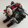
Hi. it's been a long time since last moc. on account of me moving. however i have been working on a articulated truck inspired by the Uniknick. like this one: Here it is: the model features (at the moment): - XL-motor for steering. - 2 x NXT motors for drive. Features i would like to implement: - front and rear hitch. - winch. i also mean to build a unimog u4000 or 402 cab for it. however i am not too good at building those sorts of things. i hope you can help me there. Here is the LDD file: http://www.brickshel...thout_motor.lxf Enjoy! Will upload more pictures to my brickshelf soon. http://www.brickshel...gi?m=KopMaister -
[MOC] Copper Penny Sorter
landoandrews posted a topic in LEGO Technic, Mindstorms, Model Team and Scale Modeling
Lately I've been in the mood to make MOCs that haven't ever been done before, or improve upon unique ones. I haven't seen any descent penny sorters,so if any of you guys know of any please let me know. Copper Pennies are worth 230% of their face value just because of the metal contained in them. Some people hoard the pennies so that if they're ever taken out of circulation they could melt them down and sell the metal. I'm not one of these people, but I this would be a fun and challenging moc. There's two ways to sort copper pennies from the zinc ones without any special equipment: 1)Date: Copper pennies were made from 1909 to 1982. 2)Weight: Copper pennies weigh 3.11 grams, while zinc ones weigh just 2.5 grams. Naturally I used the weight to determine what kind of penny it is. There are two scales in the machine, each one being identical. When the penny is dispensed onto the scale if it is copper it will fall off, if it is zinc it will stay on top of the scale and will be pushed off by a fork into a different direction than the copper pennies. The entire thing is mechanical, all driven by a single NXT motor. -
NXT-assisted Embroidery Machine
Legoism posted a topic in LEGO Technic, Mindstorms, Model Team and Scale Modeling
Not at all pure LEGO, but after a while I gave up trying to emulate a real sewing machine mechanism, and just went "embellishing" a real machine. Therefore, this is more of an "NXT-assisted" embroidery, than a pure solution. It's still a rather rough prototype, but it has proven the concept as worth the R&D. The X-Y fabric movements are simple - I've had much more trouble motorizing the handwheel (absolutely no grip, and occasionally huge torque required). Needle movements are imported from a program EmbroiderModder. Finally, some embroidered Classic Space, Technic and NXT logos for my bags and blank baseball caps :). A bit of extra text is here, and a YouTube video . Result that came out of the prototype after about 30 minutes of work... (the rusty old look is intentional - it can be avoided by using top and bottom threads of identical colours, rather than white & brown).