Search the Community
Showing results for tags 'Gearbox'.
Found 167 results
-
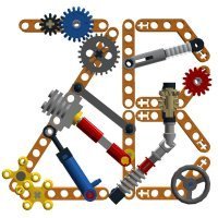
Sheepo's Sequential Gearboxes Family
Sheepo posted a topic in LEGO Technic, Mindstorms, Model Team and Scale Modeling
Today is the third anniversary of my website!! And for celebrate it I will show you many information about all my sequential gearboxes until today. With my latest cars I introduced a new sequential gearbox type, and to avoid problems with how to call this new one, I decide add a new way to call all of them. Since now the new versions of the sequential gearboxes will be called with ordinal numbers. In this ordinal numbers don't enter other gearboxes types like: dual clutch, planetary or CVT, just normal sequential gearboxes. 1st Generation This was my first sequential gearbox(I think this was the fisrt Lego sequential gearbox with more than 3 speeds, but I am not sure), I designed it in 2009 to be used in my Bugatti Veyron. The version used in my Veyron is a 7+R speeds. with a little modifitacions you can get a 4 speeds or a 5+R speeds versions. The main feature that distinguishes this generation is that it has a speed selector in linear motion, and the distance between speeds are 2 studs. Correct speeds change ratio: ~70% In Octuber 2010 I designed a second version with auto-clutch. It worked fine, but I decide not publish it beceause it was too big to be used in any car. 2nd Generation Before to finish the Veyron, I started to develope a new car(the Porsche), and even before I know what car I will build, I wanted to use again a sequential gearbox, but the Veyron's gearbox wasn't an option because it was too big. In the search of a new smaller gearbox I developed many differents prototypes. And this was one of them. Finally I decided to use a dual-clutch gearbox to be more accurate to the real Porsche. The main feature that distinguishes this generation is that it has a speed selector in linear motion, and the distance between speeds is only 1 stud. I have used this gearbox in 3 of my big MOCs until today, all of them with differents speeds configurations and add-ons. Type 1 - 2 switches(4 speeeds), without auto-stop, without clutch (Mini Cooper) Correct speeds change ratio: ~90% Here the Mini's gearbox. It was the first You can download the step by step instructions in my website. Type 2 - 3 switches(5+R speeds), with auto-stop, with auto-clutch (Land-Rover Defender 110) Correct speeds change ratio: ~80-85% Here the Lad-Rover drivetrain. This drivetrain also includes a range gearbox and a 2WD/4WD selector, but the sequential gearbox is a normal 2nd Gen gearbox. Type 3 - 5 switches(9+R speeds), with auto-stop, with auto-clutch (Peterbilt 379) Correct speeds change ratio: ~80-85% Here you can see the whole Peterbilt drivetrain. You can se the main gearbox, the drive motors, the range gearbox and the pneumatic module(compresor, compresor control and brakes control). In total 5 PF XL motors and 3 M. 3rd Generation The history of this gearbox is very strange. Like the 2nd Gen, this gearbox was initialy developed as a alternative gearbox for the Porsche, but in this case I couldn't make a good system to generetare the auto-stop mechanism, so I leave it in a box of a while... The main feature that distinguishes this generation is that it has a speed selector in circular motion. To reduce the size of the few speeds versions I created two types: one for 2 swtiches and another for 3 and 4 switches. Type 1 - 2 switches only This type change one speed for each 90º of the selector switch movement. Correct speeds change ratio: >95% I will publish some information about it comming soon. Type 2 - 3 & 4 switches This type change one speed for each 45º of the selector switch movement. This gearbox is specialy recomended for 4 switches, because with only 3 switches the saved space compared to the 2nd Gen is not significant, maybe around 5-10%. But with 4 switches the saved space is more than 20% Version 1 (V1) - Caterham Seven (with auto-stop, with clutch) Correct speeds change ratio: ~85-90% This new gearbox is more reliavable than the 2nd generation, but it still have a little problem, and I need to fix it before publish nothing more about it: it can't support high torque. I could avoid this problem in the Caterham adding an external torque converter, but this is not the ideal way to do it. Here you can see the Caterham Seven drivetrain. Version 2 (V2) - Ford Mustang Shelby GT500 (with auto-stop, with clutch) Correct speeds change ratio: ~90-95% This is a little bit smaller and more reliavable version of the 3rd gen. And with the torque problem fixed. Here the Mustang GT500 drivetrain. Future generations For the future I have some ideas for new gearboxes generations, but they are only ideas... nothing more, and I don't know when I will can have a working prototype. I hope this long explanation can help you to understand my gearboxes family and the high quantity of models developed along the years. -
Peterbilt 379 & CAT C15
Sheepo posted a topic in LEGO Technic, Mindstorms, Model Team and Scale Modeling
After many delay, now I present my new big MOC, It was in LFW in Skaerbaek. Since I was a child I has been a fan of big trucks, and specially of American style trucks(in Spain is strange to see trucks with long noise). For this MOC I have chosen one of the most charismatic and representative models of these trucks: a Peterbilt 379. Also I have endeavored to put a version of CAT C15 engine (I'm also a fan of the brand CAT). This MOC is made in a 1/10.2 scale, giving a final size of 31 studs width, 99 length and 40 high. Here you can see some pictures taken in Skaerbaek where you can appreciate the size, there are: this Pete, the Crow's Vampire GT(scale 1:10 too...), the Nathaniel's Supercar and my Veyron. The total weight is 5.5kg, and has been one of the main problems I've had. Front axles deforms and look like the wheels has huge camber angle. This is a esthetic defect which I hate, but it has not solution if I want to keep all functions and therefore the weight of the truck. I will try to fix it comming soon. The electric system is huge, and it has: - 2 AA PF battery boxes - 4 PF IR recievers - 5 PF XL motors - 5 PF M motors - 1 PF switch - 3 PF large extension wires (50cm) Probably, the most “wanted” picture for Lego Technic followers: CAT C15 Engine Under the hood you can find a replica of the CAT C15 engine, with its 6-cylinder in line. The engine doesn't have the sides covered to appreciate that the cylinders are located in the same order as the real engine, with 120 ° intervals between them. Getting those 120 º between cylinders was very complicated but I thought it was necessary to be more faithful to the original. The engine also has a motor M to rotate it, which is connected directly to a battery. Between the engine and the M motor there are a differential, which is also connected to the drive motors, so that the engine is always at idling, but when you starts the drive motors the C15 accelerate adding both speeds. The rotation speeds grow up from 250 rpm up to 700 rpm aprox. Pneumatic system After almost 10 years without using pneumatics in any of my MOCs, I decided this was the perfect model to use it. The pneumatic system the truck runs along the complete truck, mainly controlling the suspension and brakes on all axles. The pneumatic system is composed mainly: - 2 Small pumps (6L) - 1 Large pump (for emergencies). - 2 Air tanks - 7 Small cylinders - 8 Large cylinders - 7 Valves - 1 Manometer (LEGO part n.64065) - 22 T connectors - And about 5 meters of pneumatic tube in 3 colors: blue, black and light gray. All pneumatic control is located on the right side of the truck inside the fuel tank. Also in the cab, between the seats, there is a manometer to measure the system pressure, it is very useful to know how much air have you at any moment. Axles As the real truck it has live axles. Both rear axles are driven without differential between them. In each axle between the differential and the wheel the axls has gear ratio 12/20 to reduce necessary torque in the differential and protect bevel gears. The front axles uses the same steering system as the real Pete, of course the steering wheel turns too, also it turns 4 laps, again as the real Pete - Suspension The suspension is fully pneumatic in all axes, and it doesn't use any spring to help. The front axle has 4 big cylinder and each rear axle 2. - Brakes The brakes as the real truck are drum brakes, there are a drum on each side of each axle, all of them controlled by a small pneumatic cylinder. The control of these pistons are made through two valves, one for the front axle and one for the rear axles. For normal braking the brakes operate all at the same time, but only while you are keeping push the brakes botton. But you have also parking brake mode, if you push the brakes botton in the opposite direction only rear brakes works, and they will not disabled if you stop pressing botton. To remove the parking brake you only need use the normal brakes. - Auxiliar output Behind the cabin there is an auxiliar pneumatic output(blue connector), where you can connect anything you want. The valve to activate it is located before the rear-right wheel Transmission The transmission is the biggest mechanism of the truck, and it has an approximate size of 25x7x45 studs. It uses 4 XL motors for drive. The transmission has 18+2R speeds(this is true, is not a joke...). The transmission is divided in two parts: the main gearbox with 9+R speeds with automatic clutch(this gearbox is based on the LR Defender), and a transfer case with 2 speed (H and L) Joint both gearboxes the result is this: RL-1:0.261 RH-1:0.29 1L (1) - 1:0.324 1H (2) - 1:0.36 2L (3) - 1:0.432 2H (4) - 1:0.48 3L (5) - 1:0.54 3H (6) - 1:0.6 4L (7) - 1:0.72 4H (8) - 1:0.8 5L (9) - 1:0.9 5H (10) - 1:1 6L (11) - 1:1.2 6H (12) - 1:1.33 7L (13) - 1: 1.5 7H (14) - 1:1.67 8L (15) - 1:2 8H (16) - 1:2.22 9L (17) - 1:2.5 9H (18) - 1:2.78 Auxiliar electric output As I said before, the truck has an auxiliar pneumatic output, but also it has an auxiliar electric output too. There you can connect anything you want, and control it with the remote controller. To avoid leaving this connetor without any use I have added a fifth wheel(trailer connector). - Fifth wheel Note: right now I don't have intention to do a complete trailer. It is very simple and effective. The kingpin diameter is 1 stud. Finally as always, you can see a complete video with all features showed: For more detalied information visit sheepo.es I hope you like it!! -
Sequential Gearbox 3+R with clutch
piterx posted a topic in LEGO Technic, Mindstorms, Model Team and Scale Modeling
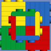
Hi guys! I was a bit unsure to post it before putting it in the car I'm building but: here's my sequential gearbox based on sheepo's one...it's smaller, only 15x13 studs and it has the one way clutch to separate it from the engine. At the moment it only has 3 gears + R because i had only 2 red gear selectors :P but you can easily extend it to 5 or more... My aim was to make something small and light (as always lol) Unfortunately i havent enough english skills to describe exactly how it works but it should be pretty clear :D It has'nt the "snap" that the sheepo's version has, so you need to pay attention when you shift gears because you can get into the neutral...but I'll try to adapt it with servo motor to make it more precise... though it's good enough. I hope you like it and you'll be able to improve it for the community's benefit :) -> some pictures to let you re-build it here's a detail of the "sled" used to move the yellow pins.... the white rim is the one way clutch (that i wrongly called "free wheel" lol) anyway, the M motor can easily be placed somewhere else, that was the fastest option i choosed :P hope this is gonna be useful for you all SHARE OR DIE !!! -
Hi, I've started my new H3t model, it has 4 speed gearbox - servo motor, double reduction after differentials (12:24, 8:24), 2 buggy motors, m-motor for steering & it also has pneumo diff-lock system controlled by RC block servo. I like how it rides))) Here's the first test-drive video:
-
4 speed sequential gearbox (servo motor shift gear system)
Jeka Jackson posted a topic in LEGO Technic, Mindstorms, Model Team and Scale Modeling
Hi everyone! I'm glad to represent my 4 speed sequential gearbox using servo motor in its shift gear mechanism. Gear rations: 1 - 1:5 2 - 1:3 3 - 3:5 4 - 1:1 Photo & video you can see here: http://www.doublebrick.ru/blogs/jackson/4-h-stupenchataya -
Hi, I have two idler/clutch gears on an axle with a clutch between them, how do I have both gears spinning when the gear lever is in 'neutral/middle' but when the clutch is put into gear 1 or gear 2 only that one spins.? Obviously more axles and gears will be underneath the above setup since its a gearbox. Note that I cant put any more gears on the same axle as the clutch as: 1 it slides with the clutch, through the idler gears 2: the axle isn't long enough Maybe a differential can sort this I'm not sure, its really hard to picture it out mentally but I'm sure its possible, I know that a differential can have just the pinion gears or everything rotating. I don't want to use any more clutches as the gear lever already is using 4/5 of them and its very wide as it is. Here is the split/assembled model, grey and black parts are technic nuts and threaded axle.
-

Don't Know if it has been done?
weavil posted a topic in LEGO Technic, Mindstorms, Model Team and Scale Modeling
Came up with this the other day. After looking and looking could not find anything of the sort. So I tinkered for a day or so and came up with this: My Linier 4 Speed Gearbox. Orange is the output. Red and Yellow(yellow) are the input. you can use either one. Blue and Green are for the shift lever. The shift lever you need and for the off set of the axle. The green and blue are just for referance. The axle for the shift lever is a 12L and 6L axle with a connecter and can be in , , or , and using or in any combonation for your install. I got a some more pictures you can see. will post when the folder is public. P.S. the shift lever can be on either end. -
Finally !!! After two weeks of work and some months of planning here it is! my most complex creation till now. It's been such a pain adding all the features in a small space that i almost gave up a week ago....then i started from scratches and now it works really nice. It employes 2 L motors 2 M motors and a servo motor powered by a single lithium battery. I didn't expect the brakes system to be so strong but its very effective even if i think the rubber parts will get damaged soon... The auto clutch lets the car stay always in a neutral gear so it can also be used like a gravity car edit: VIDEO :D! btw, here's a list of the features: - Auto clutch system - Front wheel drive - RC Gearbox 3+R - RC Rear brakes system - Power functions - Return to center steering - Front independent suspension - Openable doors and front hood dimensions: 43cm x 18cm x 14cm 1235g weight
-
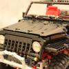
Land Rover Series I RC model
Tamas Juhasz posted a topic in LEGO Technic, Mindstorms, Model Team and Scale Modeling
Hello! After some weeks there is my newest publication, a Land Rover Series I model. I'm planned to make a real off-roader long ago, with this I wanted to build a realistic one with realistic looking chassis. It could be another famous off-roader, but this is the first Land Rover, and it matters me a lot. So the moc: http://www.brickshel...ry.cgi?f=531411 Wheels, motor, gearbox: This wheels are made from the 81,6 mm tyre and from the 56 mm wheel. This is enough narrow yet to make this model with it. The model has the standard four speed gearbox with my definite control (see my other topic for more). This model was built a few month ago, that time I didn't have my improved gearbox with the same function, but this also did it's job, at last it didn't came so much load, there is a gearing after the gearbox. One RC buggy motor is there for propulsion (the noise is it's noise - don't ask me about that, this is the standard noise of this high rpm motor). I used that because of it's high rpm, there is a lot of gearing after that including the low gear/high gear gearbox. In this model, my goal was to make a realistic looking car with a realistic looking chassis and technic, performance was secondary. With the secondary gearbox there is in all 6 speed (two is the same). Sometimes in low gear, but it goes everywhere. Chassis, suspension: The chassis is a single ladder type one, with strenghtening beams an plates. The chassis itself contains every working mechanism: The suspension is made from technic axles, to be like leaf springs, and it works like that. There are positioning links to hold in the right place the axles. A small 6 L link holds transversely the front axle. I made the housing of the differential in the rear axle: http://www.brickshel...y.cgi?i=5898328 The steering, as in the real one isn't made with gear rack, but with a linkage-like machanism. The suspension performed surprisingly good on terrain. Has handbrake, it prevents roll down in forward direction. All function is remote controlled, the on/off switching of the low gear and winch also, by two micromotors. Under the hood I placed a 4L "fake" engine: http://www.brickshel...y.cgi?i=5898334 Body, etc.: Basically the body is a simple plate body with some liftarms and bricks. Of course, the front part was the hardest section. This front look means the Land Rover itself, very easy to recognize. I tried to add many details to the body, like mirros in the left side, turning lights, number plate, door handle to be less monotonous. Inside there is a big cover from a western set, we can find under that cables and technical parts. The steering wheel works, with these old bushes: It has an advantage: the turning is smoother than U-joint drive. Except this it's only an interesting technique, typically for applications which aren't require much torque. Video: (intro is also off roader-like, I didn't find a flat surface) Main specifications: Weight: 1555 g Speed: high gear: 1: 0,50 km/h 2: 0,82 km/h 3: 1,25 km/h 4: 1,67 km/h low gear: 1: 0,19 km/h 2: 0,32 km/h 3: 0,56 km/h 4: 0,92 km/h Length: 387 mm Width: 192 mm Height: 198 mm Scale: 1:9 -
issue - Gearbox Drive Selector
SNIPE posted a topic in LEGO Technic, Mindstorms, Model Team and Scale Modeling
Hi, I am making a six speed gearbox but I am having significant trouble in enabling the gear lever to slide out of the drive selector clutch and into the clutch beside it. This is fine if the drive selector is set to the middle setting as it lines up with the clutch for the gearbox but if it isnt then it wont be able to without moving back down to the middle position and changing clutches. Any ideas? -
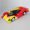
I have the pleasure to present you my latest moc. The Caterhan Seven (also called Caterham 7) is the present version of the original Lotus Seven (or Lotus 7) designed by Colin Champan in 1957. This car is very famous because it is extremly ligth, and it has outstanding dinamic specs, which make this car perfect for its use in competition and track days. The original: This creation is made in scale 1:7. Thus remains in 29 studs wide, 56 of length and 20 fo high(23x45x16cm). The weigth is 2.2kgs. It has around 2500 parts. As all my MOCs, this includes some remote controlled functions: - Steering (PF M motor) - Drive (PF 2XL motors) - Sequential 5+R speeds gearbox (PF Servo motor) - Disc brakes (PF M motor) This car arrives with a 5+R speeds version of the all-new 3th generation of my sequential gearboxes. The new generation is even more compact and reliable. Of course it has auto.clutch It has a gear indicator in the cabin. Just behind the seats, over the rear axle are the battery and the drive motors (2XL) The Seven design is based in a tubular unibody frame with double wishbone front independent suspension and DeDion rear live axle. The front axle is double wishbone type with caster angle, camber angle and ackerman steering. The original Lotus 7 had a typical rear live axle, and the newest and powerfull version has independent suspension , but the most common rear axle is the DeDion axle. Like the real one, this creation has rear 3-links DeDion axle(you can see it in more detail in the video) The "most wanted" picture. This creationa also has working brakes in all wheels(the same brakes used in my Land-Rover) Like the real Seven, this creation mantains the unibody frame. Also to reduce the weigth, the frame and the bodywork are the same thing. The yellow liftarms in both sides of the car are the bodywork, but at the same time are the frame of the car. This picture shows how the structure is made As always a little video: For more info and pictures you can visit sheepo.es Fernando
-
4 Speed Differential gearbox
Doc_Brown posted a topic in LEGO Technic, Mindstorms, Model Team and Scale Modeling
Hi Everyone! I just created this, and thought I would share, as it might give someone an idea for a us in a Moc or something. I'm thinking a car perhaps with seats on top. It could only be 3 studs high. It basically gears around the stationary motors and I'm guessing creates the following ratios. 1 motor equals 4:1 2 motors equals 2:1 3 motors equals 4:3 And 4 motors equal 1:1 output. Now if you could create a level on the remotes that engages 1 channel at a time, you would have silky smooth gear changes! Sorry if this has been done before! -

Stick Shift vs. Changeover Catches
Junpei posted a topic in LEGO Technic, Mindstorms, Model Team and Scale Modeling
So I was looking at the 8880 parts list when I discovered a strange piece. I later learned that it's used to move driving rings. Does anybody have one to compare performance-wise to the changeover catch? -
 Hi, after thinking a little bit about the realism of typical current lego gearboxes, ie. based on any combination of drivingrings and clutchgears (and regardless if sequential or not, becaue this doesn't matter), i came to the result, that "synchronized gearbox" (as often read here in many threads) is false, at least misleading, because: - In a real transmission gearbox the term "synchronized" means that the input and the output shaft are equalized in speed for the short time of the shifting action so the "dog clutch" (in lego this would be the drivingring) can catch the gear without any noise...this is typically achieved with so called "synchronizing-rings" - a typical current lego gearbox doesn't (and can not) equalize speed of input and output shafts for the shifting action cause of the lack of such synchronizing-rings So IMHO the denotion "synchronized gearbox" for a lego gearbox is somehow false, what i'm searching for is a good name for a "gears-are-always-in-mesh"-gearbox - this is also the main difference (and advantage) to the previous "crash"-gearboxes... Any thoughts rsp. ideas? Best regards
 -
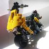
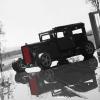
A little somthing i made last weekend. Like the real one it uses independent suspension in front and a live axle at the rear. In order to simplify design the rear axle also houses the 2 drive RC motors and the gearbox, opretaed by the geared 9V motor. Gearbox allows the truck to either climb up smaller hills with 1:3 gear ratio, or to reach some 15 km/h on the straights.
-

A new car is coming... (WIP)
jorgeopesi posted a topic in LEGO Technic, Mindstorms, Model Team and Scale Modeling
A few pics... It will be RC with a 7 speed and reverse manual gearbox like in my Huayra but this is 4WD. For the moment the hardest part was to build a front drive axle with servo motor and only 23 studs between wheels, most commonly they are 25 like in the rear axle but the proportions of the car are so. I don´t know yet what motors use or how many, I have room enough which is the most important thing and also works with a RC motor or a L motor worked fine. -
Contents of this re-post were kindly resurrected from the 5 days of lost topics by Boneparte. ----------------------------------------------------------------------------------------------------------------------------------------------------------------------------------- This is my MOC of the ubiquitous British Class 08 diesel shunter in 8mm:1ft scale. It has been eagerly awaited by those involved in the PF L-Motor discussion. I'm now at the stage where the functionality and basic body are there but I still have the trimmings to do - railings, ladders, fuel gauge, buffer beam and grille improvements, as well as cutting down the rods and their pins. On a Hornby layout these engines melt into the background so I wanted to make this a bit special. My plan was to create the model with 3 essential functions: - Maximum speed around the design speed of 20mph. - Minimum steady speed of 0.5mph for shunting at prototypical speeds. - Decoupling to remove "Hand of God" operation. The model contains a gearbox, actuated by a PF M-motor, which selects between high ratio, low ratio and decoupling. The drive motor is a PF L-motor and the wheels are from an Emerald Night set. Lots of traction with the red belts! I have put functionality before aesthetics as usual. The loco is in Cotswold Rail livery, of which no. 08871 is an example. i understand the company owns 6 of this class of loco. I took the easy route so far, just quantising the livery into brick widths and plate heights. As long as it's recognisable it'll do because I'm not trying to represent them. The grey with bright lettering will make a change from the green or blue of many other British locos. In order to create the functions, the two motors, gearbox and IR receiver have to fit inside. This means the model is slightly long for the scale but at least it fits into the required height and width. The length is grille + 2M of IR receiver + 8M of battery box + 7M of motors + gearbox + cab end. The coupling system can cope with the extra length so there is no compromise on shunting ability. The wheels are a bit small for the scale but this is common to other vehicles at this scale using standard LEGO train wheels. The Emerald Night wheels were selected for red-belt traction in preference to the larger BBB wheels that do not have a belt groove. The loco has two of the distinguishing features, the first is the yellow radiator grilles on the front. I could add more striped tiles to the side battery boxes later: The second is the yellow striped cab end, for which I cut up a few 1x4 tiles, ensuring that I could use both halves of every one I cut: The cab end windows would be nearer the sides on the real loco. This would be difficult to make, requiring a lengthways cut of 1x4 tiles and then a few 0.5x1 parts for the other side. This was a cut too far, but might be a sticker job for someone else. The IR receiver is nicely hidden at the front, behind the radiator grilles that open just like those of the real loco. This allows for changing channel. The grilles will pass IR light easily enough and I used clear plates behind them to also pass the light through to the receiver. It still needs care because the controller has to be able to see the front to operate it! I tested the loco through the fiddle yard of my large looped-eight layout. I think insufficient speed is a greater challenge than lack of IR controllability. I made an IR repeater circuit for use in tunnels. One criterion for exhibition is that the public should always be able to see a train moving at a show. Spending too long hidden in a fiddle yard will not do! Therefore I'm happy with this loco stayng on top in the yard, leaving other locos to do trip workings. I will take and post more internal pics in due course because I'm sure you'd like to see the gearbox! For now here's an underneath pic: You can see the coupling mechanisms using 2x8 plates with holes. These connect to the 9M racks that are supported by 5M black studless beams. From each rack there is an axle with a z16 cog on the rack and a z8 cog driven by a worm. The 2 worms are on an extended shaft driven by the gearbox and each has the same amount of play in its axial location. This allows lateral movement of the coupling over a limited range to cope with changes in the track curvature. The range is moved by the decoupling mechanism. In the picture the decoupling drive would send one coupling up and the other down or vice versa. The direction may be selected because the decoupling operation might take place on a curve in either direction. The z24 cogs keep the wheels in sync and the rods are more for show. I have a prototype where the rods did the work successfully. The drive omes from the gearbox onto the middle cog. This is in preparation for a test to see whether another chassis could be articulated whilst keeping the wheels in synce with the chain of cogs. This would have variable legth rods, a technique I used on by Class 14 loco. The idea of the articulation is that the chassis at the moment is the longest that can get round standard curves. It is also OK on flexitrack but needs to take care on points, especially with the moveable blade and the check rails. It would be nice to improve reliability of operation over points, especially for a shunting loco! The light bley parts with 2 pins each are the main Technic to stud connectors. Studded beams with holes are used in the cab and these hold the cab end body to the Technic parts of the gearbox. At the left hand end you can see some of the cogs in the cab, either side of the coupling 2x8 plate. I used 2x4 tiles and some hinge bases to hide varous cogs because they extend to more than 6-wide inside. One window is a composite for the same reason. The gearbox width is the reason the bodyside grilles by the cab windows currently stick out too far. I plan to revise that bit. On the roof the IR receiver plug is clearly visible on top of the PF LiPo battery box. I was pleased to be able to minimise studs on the roof on this occasion - a number of my trains might benefit from a refresh in this aspect, now that we have a good range of cheeses and curved parts. There is a 2x2 tile that sits proud, covering the on/off switch. Originally it was just the tile and a 1x1 round plate underneath but I added a minifig flipper to help the tile to stay in its slot. I might change this if another part is more suitable but it needs to have a small bit to actuate the button and a stud on top to attach the tile. I am particularly pleased with the crawling ability of this loco. It has been able to push a heavy loco with two depowered 9V train motors, enabling it to shunt locos as well as rolling stock. LEGO trains have had issues with crawling ability, either being unable to get enough torque at low speed or overheating 9V train motors in the process. Therefore this gearbox technique applies particularly to fans across the pond where trains go so slowly! I would put a gearbox in a larger loco so as to have a crawler gear and a high-speed gear. The gear ratio between low and high speed is currently 9:1 for 0.5mph minimum and 20mph maximum and is a squeeze in this loco, not so bad for a large loco. However, some motor torque is robbed by having the geartrain connected because in high ratio the motor has to turn the low ratio shaft 9x as fast! A higher ratio would suffer more in this respect, whatever the loco size, so a high speed of 60-70mph for a large loco (3x as high) would be a challenge. I have some ideas about this though. This is a true Power Functions loco - crammed in with a skin of bricks! I am considering whether adding lights is possible - there is a small space in the cab that might fit their 2x2 bricks! This folder has more whole-model pics and I will post some internal photos soon, but please let me know what you think so far. ------------------------------------------------------------------------------------------------------------------------------------------------------- Since the original post I am investigating whether it is possible to make the lower chassis flexible, allowing the front and rear wheels to steer. This will improve performance on curves and especially points. If it works I'll use flanged centre wheels and replace the rods with flexible ones more like those on my Class 14 loco (colour TBD). I deliberately made the drive from the gearbox go to the centre axle with this in mind so I hope the upper body doesn't have to change too much. The key at the moment is making the chassis pivot points rigid so that there is negligible vertical movement - just enough to work with a change of track slope. Mark