Search the Community
Showing results for tags 'mindstorms'.
Found 225 results
-

EV3 GBC starter module?
Huaojozu posted a topic in LEGO Technic, Mindstorms, Model Team and Scale Modeling
I have recently become interested in the art and science of GBC and I am looking for the best way to start building. One problem though, I don't like to mix my sets . I have seen some great GBC c-models (such as https://www.youtube.com/watch?v=lb5kTm9Ykn0 ) but unfortunately haven't been able to find any instructions. In particular I am looking for simple GBC modules made of single sets to study the entire GBC mechanic and learn from it to make my own modules. It doesn't really need to be fancy or cool, just functional and c-model-ish. Has anyone come across something similar? It seems that in all topics I've found, the possibility of making modules as c-models of existing technics sets isn't really discussed. -
RotoShift Gearbox and Function Switcher
TheMindGarage posted a topic in LEGO Technic, Mindstorms, Model Team and Scale Modeling
I've made a new gearbox for my next car. This gearbox can either be set to a gear ratio (driving the wheels) or to a function, allowing the drive motors to power something else. In total, there are 4 forward gears, 2 reverse gears and 6 function "ports". The reverse gears weren't intentional - they happened to exist when I added the gearing for the forward gears. The gearbox consists of a turntable with an off-center gear positioned on it. This design uses two off-center gears on the same axle - an 8t and a 12t. This allows more meshing combinations. The off-center gears are driven by a 24t gear in the middle of the turntable, which is powered by the drive motors. Around the turnable, there are many axles with gears on them (12 in this design). When the turntable is rotated correctly, one of the off-center gears meshes with one of the gears on the outside, turning that axle. Some of the axles are connected with extra gears to form a transmission with different speeds; the unconnected ones will be used for functions. Here you can see the internal workings of the gearbox. These are the gear ratios (including the 3:5 gearing before the transmission): Gear 1: 1:2.5 Gear 2: 1:3 Gear 3: 1:4.167 Gear 4: 1:5 Reverse 1: 1:3 Reverse 2: 1:5 Functions 1, 3, 4 and 6: 1:7.5 Functions 2 and 5: 1:5 The gear ratios are rather close, and the reverse ratios are too high, but there is little choice in choosing gears since all of them have to mesh properly with the off-center gears on the turntable. I made all the gear ratios quite high since I'm planning to drive the vehicle with 2 EV3 Large motors, which have tons of torque. There are two inputs - this is purely because I plan to use 2 EV3 Large motors - one on each side of the gearbox. The shifting input drives the turntable with a 28:8 gear reduction - this could be increased, possibly with a worm gear. Note that it is ESSENTIAL to use a MINDSTORMS motor for shifting, since the shift positions are in strange places and not in order. This gearbox can handle plenty of torque - the gearing up before it does help. However, when under high load, the turntable can move out of place and make gears grind. This gearbox works best with minimal backlash on the shifting input. Also, some clever programming can make the turntable adjust its position a little bit depending on the amount and direction of the load, countering the forces pushing the gears apart. The gearbox is very compact for its functionality - comparable in size to a 4-speed sequential gearbox. However, it can only be used with a MINDSTORMS motor for shifting, which will make it useless for most of you guys (unless of course someone develops a version that can be controlled by a PF servo...) -

[EV3] Advanced Programming
johannp02180 posted a topic in LEGO Technic, Mindstorms, Model Team and Scale Modeling
I am new to this blog and don't know how things work yet. I have a few questions about some programming I am having trouble with and wanted to see if the community can provide me with some programs they've built. 1. I want a program so that you can press the touch sensor ex. 2 times, it would run the 2nd program; press the touch sensor 4 times it would run the forth program etc. Or have a color sensor and I put a red brick in front of it and it runs a specific program. 2. I have a wall follower program and I am wondering if it can follow the wall for about 24in or so and then stop and do some other action. Does anyone have an idea on how to do this, and can you provide a program? I can't figure out how to program these. Any tips, programs, would help! -

Lobst3r, a walking robot
Aswin posted a topic in LEGO Technic, Mindstorms, Model Team and Scale Modeling
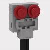
This is Lobst3r, the walking robot that can walk in any direction. It goes forward, sideways, it can turn and even rotate on the spot. Robots that can go in any direction are called holonomic or omnidirectional robots. Most holonomic robots are made with special wheels. This robot however is a walking robot. Its legs implement Klan linkage to walk. But the real trick is in the toes of the legs. The wheel on the tip of each leg is the secret to its holonomic capabilities. This small wheel is mounted perpendicular to the direction of the leg. As a result, the leg can roll sideways without any friction whilst still having friction in the walking direction. The base of the robot is triangular, the simplest form to create a holonomic robot. On each side are 4 legs that are linked to a single medium EV3 motor. An additional NXT motor under the tail of Lobst3r powers the claws of the robot. The robot has two ultrasonic sensors that are used to detect objects in front of the robot. If it sees an object it will try to walk around it. If that doesn't work it will snap it claws in self defence, back up, rotate and walk away. The US sensors are switched on and off to prevent one sensor picking up the echo's from the other sensor. As a result the robot seems to blink with its eyes The program is written in leJOS. LeJOS offers standard code to implement holonomic robots. -
[WIP] Koenigsegg Regera EV3
TheMindGarage posted a topic in LEGO Technic, Mindstorms, Model Team and Scale Modeling
At the moment, this is just an idea - since I have two cars currently half-build, I will finish them before doing this. Expect this sometime in October (knowing me, near the end of it ). This will be about 1:10 scale with 68.8x36ZR tyres. As with all my cars, this won't be a strict scale model - I just want the car to be recognisable, functional and fast. These are my plans: Power will come from my entire EV3 arsenal - 3 EV3 Large motors and one EV3 Medium motor. These will be connected in a very strange way. The Large motor and Medium motor (geared down 5:3) are combined with an adder. This output will go into a second differential with one Large motor on each side. Each side will then be geared up (hopefully 1:9) before going to the wheels. I haven't tested this setup - I really hope the diffs are strong enough . I might need to gear up the motors 1:3 before the diff and 1:3 after the diff, but I'd rather avoid this if I can since it would mean more sets of gears. When turning, the Large/Medium combo (representing the ICE) will have to slow down a little bit, as will the Large motor on the inside of the turn. Steering will not be motorised - my plan is for the front wheels to be able to steer freely (maybe with a rubber band to provide a little self-centering) but have a high castor angle. When the motors on each side of the diff turn at different speeds, the front wheels will steer automatically. Essentially the fastest castorbot ever! Suspension is still undecided. Depending on the layout of the drivetrain and my chosen width (the math says 26 studs - I have a choice of 25 or 27), the rear suspension may either be independent or an independent trailing-arm type. Whatever I go for, I would like something that replicates the triplex suspension in the real car. Front will be regular independent, with the wheels free to pivot. Making the ride height adjustable would be a bonus. I'm also hoping to make proper Koenigsegg doors and have some space for a cabin. -
 Sioux.NET on Track is a group of enthusiastic colleagues who come together after working hours to get experience with Microsoft.NET. To make learning fun, we develop an application in C# for making a full automated Lego train, using Lego Mindstorms and Lego Power functions. The layout is always shown at Lego World in the Netherlands. Our plans for 2016 have been published at our blog: siouxnetontrack.wordpress.com as well as an article about the new updated crane positioning. You can also view a video at our Youtube channel about the power chain systems: Enjoy, Hans
 -

[EV3] Mindstorms High Performance SUV
DamonMM2000 posted a topic in LEGO Technic, Mindstorms, Model Team and Scale Modeling
Last month marked the second anniversary of my YouTube channel, so I decided to recreate the first video I posted: a high-speed Sport Utility Vehicle. In different ways, my production skills have improved, and in other ways, not as much. I think I still have a lot to work on... do you guys have any suggestions? I'd like to know how my videos are perceived. Thanks to all who have been watching my videos and have subscribed! -
[EV3] Rally Racer
DamonMM2000 posted a topic in LEGO Technic, Mindstorms, Model Team and Scale Modeling
Rally Racer is the successor of Rally Rac3r. The difference? This Rear Wheel Drive race car is a tremendous success. As complimented by Karl4123, this vehicle has "sleek and stylish looks." It is geared up 36:12 or 3:1, and it is decently quick with decent torque. Many styling cues have been added. Why is there no InfraRed Sensor, you may ask! Well, thank you for asking! With the help of Builderdude35's tutorials, Rally Racer drives via Bluetooth! Rally Racer's Intelligent Brick acts as a receiver, and a second Ev3 Intelligent Brick is the remote! In this way, I am able to control Rally Racer from 200 feet away. Rally Racer features twin dual exhaust. The taillights feature vents which mimic the outsource of airflow, similar to that of the Ferrari 488 GTB. The spoiler is a low, lean downforce-inducing wing. The headlights are a twin-cluster with a main headlight and an auxiliary tinted light, not including the rally style fog lights. The chassis is extremely compact in and of itself. I borrowed the drivetrain design from Builderdude35's Falcon FAV100, so thanks! Two Large Motors drive a 36z gear which drives a half-bevel 12z gear (these are encased about an H-frame). It then transfers drive both to the front and rear of the robot. There is a differential which transfers power to the rear wheels, while the front axle extends to the front of the car as a neat auxiliary cue. The rack and pinion steering setup is controlled by a Medium Motor, and stabilized with a LEGO rubber band. Check out the metallic exhaust tubes while you're at it! Please comment if you have any questions or... comments. I appreciate any feedback whatsoever. I am quite please with how this turned out, especially when comparing this with my original Rally Rac3r model. -

[MOC][WIP] LEGO EV3 Laser Harp
MajorAlvega posted a topic in LEGO Technic, Mindstorms, Model Team and Scale Modeling
Hi all! About an year ago, while tinkering with lasers and fog, I had this crazy idea of building a laser harp. It finally reached a level where one can actually play it, so I'm showing it here: It's not a great LEGO MOC - just a framework to hold 7 EV3 color sensors and 7 Power Function Lights (to be replaced with 7 red 1 mW lasers in the future). I use 2 Mindsensors multiplexers to connect 6 of the color sensors to 2 of the EV3 inputs. The 7h sensor is connected directly to a third input. The fourth input is reserved for an ultrasonic sensor, I hope to read hands distance to control notes amplitude. The 7 PF Lights are connected to one output port so I can control brightness. A second output port will be used to control a fog machine. I'm running ev3dev (Debian linux for the EV3). It has some support for music but not [yet] for MIDI. I decided to use MIDI because it allows polyphonic sounds and also choosing different instruments so I'm sending the notes to my linux laptop to be played by a software MIDI synthesizer there. Software is very basic, just two python scripts (one at the EV3, the other at my laptop). For those who might be interested, I'm publishing some more details (and the code) at my blog. -
[EV3] Technic Jim's Mindstorms EV3 Thread
Technic Jim posted a topic in LEGO Technic, Mindstorms, Model Team and Scale Modeling
Hello all! It has been a while since I have posted here but I have got a new toy! It is on loan to me for the summer and I plan to use it well. This thread will be where I post all my creations and hopefully the programs. I have a few programs ready and waiting to be filmed and a lot more ideas. None of them have been filmed yet, but here is a trailer to wet your appetite!: As usual, please leave any constructive feedback and keep popping back because I will (probably should!) be updating this thread fairly often. Technic Jim -
9797 NXT Base Set Unboxing (HD)
DamonMM2000 posted a topic in LEGO Technic, Mindstorms, Model Team and Scale Modeling
In this video, I show you what exactly comes in the 9797 Lego Mindstorms NXT Base Set with this stop-motion style unboxing. If you liked this video and would like to see more unboxing videos in this style, please let me know! -
[MOC] Nissan GTR with EV3
TheMindGarage posted a topic in LEGO Technic, Mindstorms, Model Team and Scale Modeling
This is my first MOC on this site! Bear in mind that I have only been building for slightly more than 2 years and don't have a very large collection, so my builds aren't exactly Sheepo standard... The car is a 1:10 model, although I had to deviate from the scale slightly in order to fit the functionality I wanted into the car (width was increased to 25 studs for example). Here are the features (LONG list): Remote control drive with three EV3 Large motors. Top speed around 5mph. Drive goes to all four wheels via two diffs. Remote-control steering with EV3 Medium motor. Turning radius is rather large though. 8-speed automatic hybrid gearbox. Basically a 4-speed automatic and a 2-speed ratchet gearbox (inspired by Sariel) used together. A model piston engine (V6) in the front with engine capacity scaled to the real car (I measured mine at 3.77cc, real car is 3.8l). Lever in cabin with Drive/Neutral/Brake settings. Handbrake system and rear friction brakes. Full independent suspension with negative camber angle. Adjustable ride height for each wheel through tuning dials (front ones are under the hood, rear ones are hidden next to the spoiler). Adjustable castor angle for each of the front wheels (adjusted by rotating the turntables). Opening sprung doors with locks. Opening sprung front hood. Cabin with fake steering wheel (non-rotating), FOUR SEATS and a floor. Pic with doors and hood open, revealing the model engine. The red pads on the hood are rubber friction pads (from EV3 Education Expansion set) - these keep the hood closed. Close ups showing the piston engine and suspension. When the tuning screws are turned, a worm gear system rotates the arm where the shock absorbers are mounted. Adjustment range is about 2 studs. Castor is adjusted by turning the turntables - this effectively rotates the entire suspension system relative to the chassis. Beams from the chassis are placed to interfere with the rotation of the turntables - this keeps the turntables in place when not adjusted. The cabin is fitted with a full set of 4 seats, as in the real car. The occupants of the rear seat are given the rare treat of having gears from the 2-speed ratchet gearbox right next to them. When the drive setting is enabled, a driving ring allows the motors to drive the 4-speed gearbox. In neutral, the driving ring meshes with nothing, letting the car roll freely. In Handbrake, the driving ring locks the input shaft of the 4-speed gearbox to the output using a gear ratio that isn't part of the gearbox, effectively locking the shaft. This is like solving the equation 3x=x (x is the rotation speed of the shaft) - x can only be zero. Part of the drivetrain is shown here. The differential and elastic system measures the resistance on the input. The system on the bottom-left shifts gears when the resistance is too low or high. The 4-speed gearbox is a standard 5/3/1.67/1 design - the 2-speed's gear ratios fit "in between" these. Notice the towball links and lever below (remember this is an upside-down view) the gearbox. Those control the rear brakes. In Handbrake mode, the brakes are engaged. Here is a graph showing the 8 power bands (created with Microsoft Excel). The lines are cut off when the spreadsheet calculates that the motors run out of torque. This graph used data from my test runs, so the performance shown here is similar to that in real life. Top view of the rear with the body removed. The drive motors are visible, and the 16-tooth gears (used as tuning dials for the rear suspension) can be seen. This is the underside of the rear axle. When the towball link is pulled, the red rubber pad swings outwards and grips the inside of the wheel. I made the rather radical decision to leave the EV3 brick exposed at the back. I decided that covering it up would require too many parts, add too much weight and deviate from the scale. The GTR's four red rear lights are modelled with new-type 16-tooth clutch gears. Overall, I think this has been a successful build for me, cramming in far more features than any of my prior builds (in fact, I am yet to see a 1:10 supercar model with more functionality). However, some things could have been improved: It isn't a perfect scale mode. The seats are way too far forward - I had to do this to fit the monstrous powertrain inside. The rear end aesthetic requires, well, some getting used to. Rear wheels sometimes rub against the top of their fenders. Can be solved by setting the tuning to maximum ride-height. Negative camber angle is too pronounced. Steering lock is very small, and gets even smaller if castor angle is set to extremes. Gearbox tends to be rather "reluctant" to shift gear - this was the only way to stop it from constantly alternating between two gears. It isn't exactly GTR like when driven. GTRs are known for their acceleration, but the model takes ages to get up to speed. It drives more like a truck. My next build will be my Porsche competition entry - no EV3 will be involved for that, although plenty more features (did someone mention 4-wheel steering?)... -
[Mindstorms] NXT with leJos spewing garbage on screen
MikroMan posted a topic in LEGO Technic, Mindstorms, Model Team and Scale Modeling
I've been testing leJos with my old NXT brick and something seems to be wrong.When I flash the brick with latest leJos firmware, it works fine. After some time, it starts spewing some garbage onscreen: The only thing I can do is press Off button, but then it doesn't boot up again and I need to try multiple leJos/official firmware reflashes to get it to work. Has anyone encountered anything like that? Any help would be greatly appreciated. -
[HELP] Lego EV3 Calculator
Technic Jim posted a topic in LEGO Technic, Mindstorms, Model Team and Scale Modeling
Hello all, I have been working on a Lego EV3 calculator recently and have incorporated quite a few functions into it.However, there are two functions I would like to add that I don't currently have. The functions that are already in it are as follows: Add Subtract Multiply Divide Exponential Square root Factorial (this was a pain to make!) Sin ASin Cos ACos Tan ATan The two that I would like to add are an Xth root of Y function and a Log() function. If anyone knows any way I can program these blocks or any ways you have seen yourself, please post a reply! Thanks, Jim -
I'll call LEGO customer service in the morning (actually later today, yes I am up late ). Hoping someone here has a quick fix. I have a new EV3 brick with rechargeable battery. Recharged the battery while attached to the brick, the brick was initially on, then auto-powered off about half way through. Now, the brick will not turn on - the center button does not move nor can it be depressed - no 'click' when pressed, left/right up/down back buttons all 'click' as normal. Any thoughts on how to reset or what's up. I get the same result regardless if rechargeable or AA alkaline batteries are used.
-
Hi folks, It is one of my earlier builds that I want to share with you: an automatic railway crossing. The LDD sketch: The barriers of the crossing are powered by two medium PF motors. I use two PF receivers: one to control the PF motors of the barriers, and one to control the lights. The two PF lights are crosswise connected to the PF receiver. By this means, I am able to get flashing lights and add sound. All of this above is controlled by a Lego Mindstorms NXT and an Hi-Technic HR link (in case you don't know: with the HR link you can translate Mindstorms commands into PF commands). In the video below you can see and hear the result: In the video below you can see the result in a small train layout. A PC application controls the two trains (both having a Mindstorms NXT + HiTechnic sensor to control the train) and also the Mindstorms NXT that controls the railway crossing. Hope you like it. /Hans
-
 Teaser: Introduction The article describes the experience of using the Lego Mindstorms EV3 set for creating a robot prototype with software and manual control via Robot Control Meta Language (RCML). Next, we will discuss the following key points: Assembly of the robot prototype from the Lego Mindstorms EV3 set. Quick RCML installation and configuration for Windows. Robot software control based on EV3 controller. Manual control of the robot peripherals using a keyboard and a gamepad. Jumping a little ahead, I will add that for implementing control over a Lego robot via a keyboard, one will have to create a program containing only 3 lines of code. More information about it is available under the cut. Step 1 First, the Lego Mindstorms EV3 set was used for creating a prototype robot to be used for programming and manual piloting. The robot's design is similar to that of a truck chassis. Two motors installed on the frame have one common rotation axis connected to the rear wheels via a gearbox. The gearbox converts the torque by increasing the angular speed of the rear axle. The steering system is assembled on the base of a bevel gear speed reducer. Step 2 The next step is RCML preparation for working with the Lego Mindstorms EV3 set. Download the archives with executable files and library files rcml_build_1.0.6.zip and rcml_modules_build_1.0.6.zip. The following describes the quick start procedure for ensuring interaction between RCML and the Lego robot controlled by an EV3 controller. Content directory after extracting the archives Next, one has to create configuration file config.ini to be placed in the same directory. To implement control over the EV3 controller via a keyboard and a gamepad, connect modules lego_ev3, keyboard and gamepad. Listing of configuration file config.ini for RCML [robot_modules] module = lego_ev3 [control_modules] module = keyboard module = gamepad Next, the EV3 controller should be paired to the adapter. The instruction for pairing an EV3 controller to a Bluetooth adapter: The reference guide contains an example of pairing a Lego Ev3 controller to a PC running under Windows 7 operating system. Next, go to the Ev3 controller settings and select menu item "Bluetooth". You should make sure that you have set the configuration settings. “Visibility” and” Bluetooth” should be ticked. Go to "Control Panel", select "Devices and Printers", and "Bluetooth Devices". Click on the "Add device" button. A window with available Bluetooth devices will open. Select "EV3" device and click "Next". Dialog box "Connect?" will be displayed on the EV3's screen. Check as appropriate and confirm by pressing the center key. Next, the "PASSKEY" dialog will be displayed, enter digits "1234", and confirm the key phrase for pairing the devices by pressing the center key at the position with the tick image. In the pairing wizard of the device, a form for devices pairing key will appear. Enter "1234" and press "Next". A window with confirmation of successful device connection will appear. Press the "Close" key. At the PC, return to "Control Panel", select "Devices and Printers", and "Bluetooth Devices". The paired device will be displayed in the list of available devices. By double clicking, go to “EV3” connection properties. Next, go to the "Hardware" tab. By double clicking, go to the connection properties of the "Standard Serial over Bluetooth link". The COM port index specified in the properties should be used in the config.ini configuration file of the lego_ev3 module. The example shows Bluetooth connection properties of a Lego EV3 controller with the use of a standard serial port COM14. Further module configuration is limited to specifying the address of the COM port used for communication with the Lego robot in the configuration file of the lego_ev3 module. Listing of configuration file config.ini for the lego_ev3 module [connections] connection = COM14 [options] dynamic_connection = 0 Now configure the keyboard module. The module is located in the control_modules directory, then keyboard. Create configuration file config.ini next to the keyboard_module.dll file. Before creating a configuration file, specify the actions to be performed by pressing keys. The keyboard module allows using keys with a certain numeric code. The table of virtual key codes is available here. As an example, I will use the following key press events: The up/down buttons are used to rotate the rear wheels motor forward/backward. The left/right arrows turn the wheels left/right The configuration file of the keyboard module describes which axes are available for the programmer to implement interaction with the robot in the manual mode. Thus, in the example we've got two control groups - these are keyboard axes. To add a new axis, stick to the following rules of axes description. Rules for describing axes for the keyboard module. 1. In case of adding a new axis, add axis name property to section [mapped_axis] and set it equal to the value of the keyboard key in HEX format; there may be several keyboard button values for one axis. In general, an entry in the [mapped_axis] section will look as follows: axis_name = keyboard_button_value_in_HEX_format 2. You should set the maximum and the minimum values that the axis may take. To do so, add to the config.ini configuration file a section named as the name of the axis, and set the upper_value and lower_value properties for passing the values of the axis' maximum and minimum. In general, the section looks as follows: [axis_name] upper_value = the_max_axis_value lower_value = the_min_axis_value 3. Next, you should determine what value the axis will have after a previously defined button on the keyboard is pressed. The values are defined by creating a section with the name consisting of the axis name and the value of keyboard button in Hex format, separated by underscores. To set the default (not pressed) and pressed state values, unpressed_value and pressed_value are used, where the values are passed. In general, the section in this case will look as follows: [axis_name_keyboard_button_value_in_HEX_format] pressed_value = axis_value_with_pressed_button unpressed_value = axis_value_with_released_button To implement the control over the robot prototype, a configuration file of the keyboard module has been created, which includes the "go" and "rotate" axes. The "go" axis is used to indicate the direction of robot movement. When the “up arrow” button is pressed, the axis is set to 100, and when the “down arrow” button is pressed, the axis is set to -50. The rotate axis is used for setting the front wheels turn angle. When the "left arrow" button is pressed, the axis is set to -5, and when the "right arrow" button is pressed, the axis is set to 5. Listing of configuration file config.ini for the keyboard module. [mapped_axis] go = 0x26 go = 0x28 rotate = 0x25 rotate = 0x27 [go] upper_value = -100 lower_value = 100 [rotate] upper_value = -100 lower_value = 100 [go_0x26] pressed_value = 100 unpressed_value = 0 [go_0x28] pressed_value = -50 unpressed_value = 0 [rotate_0x25] pressed_value = -5 unpressed_value = 0 [rotate_0x27] pressed_value = 5 unpressed_value = 0 Next, for control implementation using a gamepad, configure the gamepad. Configuring the module includes creating configuration file config.ini next to gamepad_module.dll in the control_modules directory, followed by gamepad. Listing of configuration file config.ini for the gamepad module. [axis] Exit = 9 B1 = 1 B2 = 2 B3 = 3 B4 = 4 L1 = 7 L2 = 5 R1 = 8 R2 = 6 start = 10 T1 = 11 T2 = 12 RTUD = 13 RTLR = 16 LTUD = 15 LTLR = 14 arrowsUD = 17 arrowsLR = 18 [b1] upper_value = 1 lower_value = 0 [b2] upper_value = 1 lower_value = 0 [b3] upper_value = 1 lower_value = 0 [b4] upper_value = 1 lower_value = 0 [L1] upper_value = 1 lower_value = 0 [L2] upper_value = 1 lower_value = 0 [R1] upper_value = 1 lower_value = 0 [R2] upper_value = 1 lower_value = 0 [start] upper_value = 1 lower_value = 0 [T1] upper_value = 1 lower_value = 0 [T2] upper_value = 1 lower_value = 0 [RTUD] upper_value = 0 lower_value = 65535 [RTLR] upper_value = 0 lower_value = 65535 [LTUD] upper_value = 0 lower_value = 65535 [LTLR] upper_value = 0 lower_value = 65535 [arrowsUD] upper_value = 1 lower_value = -1 [arrowsLR] upper_value = 1 lower_value = -1 Step 3 The next step is writing a program in the RCML language. At the root of the created directory, create the program file. The name and extension of the program file may be anything, however, Cyrillic characters are to be avoided. In the example, the filename is hello.rcml. For the lego_ev3 module, the robot redundancy program code looks like: @tr = robot_lego_ev3; The lego_ev3 module connection page contains description of the majority of the features supported by the controller. As a test example, a program for automatic robot drifting has been created. The algorithm of the program is as follows: function main() { @tr = robot_lego_ev3; //Reservation robot @tr->setTrackVehicle("B","C",0,0); //Installing the engine synchronization @tr->motorMoveTo("D",100,0,0); system.sleep(500); @tr->trackVehicleForward(-100); system.sleep(1000); @tr->motorMoveTo("D",50,-50,0); system.sleep(4000); @tr->motorMoveTo("D",50,50,0); system.sleep(4000); @tr->trackVehicleOff(); system.sleep(1000); } After reserving the first available robot, two motors are paired for further operation as one. After that, the robot starts drifting. Program description of robot actions makes it possible to precisely set front wheels turn angles and rear wheels rotation speed. Using this method allows achieving the results that are difficult to replicate by manual piloting from a keyboard or a gamepad. The program is compiled in the windows command line. First, navigate to the new directory with the rcml_compiler.exe and rcml_intepreter.exe executables. Then enter the following commands. The command for compiling the hello.rcml file: rcml_compiler.exe hello.rcml hello.rcml.pc The result of compilation is a new hello.rcml.pc file in the created directory. Now make sure the EV3 controller is enabled, and paired to the Bluetooth adapter. A gamepad should be connected to the PC. After that, run the program file execution command: rcml_intepreter.exe hello.rcml A video showing the robot motion program is located below this article. Step 4 The next step is controlling the robot manually, using a keyboard. The following describes the process of software pairing of robot motors to the keyboard. Keyboard can be used for controlling any motor of the robot. Within the framework of the example, control over the following mechanisms has been implemented: Front wheels turn angle, Direction of rear wheels rotation. The algorithm of the program is as follows: function main() { @tr = robot_lego_ev3; @tr->setTrackVehicle("B","C",0,0); system.hand_control(@tr,"keyboard", "straight","go", "speedMotorD","rotate"); } Then the program should be compiled and executed. The result of manual controlling a Lego robot via a keyboard is shown in the video at the bottom of the page. Step 5 In addition to the keypad module, the gamepad module is available, which makes it possible to manipulate the robot using the gamepad. For implementing control over the robot via a gamepad, one should describe at the program level what axes of the robot will be set to the values of the gamepad axes. The algorithm of the program is as follows: function main() { @tr = robot_lego_ev3; @tr->setTrackVehicle("B","C",0,0); system.hand_control(@tr,"gamepad", "straight"," RTUD", "speedMotorD"," RTLR"); } Then recompile the program and execute it. Below is the result of manual control over a Lego robot via a gamepad, and all previously connected methods: Control Lego Ev3 by using RCML The article briefly shows only certain RCML features. A more detailed description is available in the reference guide.
 -

Lego Typing Machine v.3
technical posted a topic in LEGO Technic, Mindstorms, Model Team and Scale Modeling
Ladies and gentlemen, I present LEGO Typing Machine Mk. III. This a follow up to typing machines I built 5-6 years ago. It types my name. 100% LEGO. A dog interrupts. -
FLL 2016 Fuzzy Logic Team
Technic Jim posted a topic in LEGO Technic, Mindstorms, Model Team and Scale Modeling
Hello all, Firstly, I would like to apologise about the text wall - I got a bit carried away I am writing here on behalf of a FLL (First Lego League-there website address is http://www.firstlegoleague.org/) team I am part of called Fuzzy Logic. For those of you who do not know what FLL is, it is a Lego Robotics competition for school children. There are four parts to winning the competition and they are as follow 1: Robot performance The robot you build has to be a Lego Mindstorms one (it doesn't matter what generation) and it will perform on a mat with various different challenges on. The more challenges you complete, the more points you get. 2: Robot Design This category is about how well built the robot is and what functions it has as well as how innovative it is 3: Core values How well you wok together as a team and with other teams 4: The project The project will be set around a pre decided topic which is decided by First, the people who run the FLL. This year the theme was trash and I will be talking about that later All of these aspects will be individually judged and you will be given an overall score. If you are the highest in your region (for Fuzzy Logic this is the south West) you will go through to the nationals that are to be held in Loughborough this year. We won our regional area along with a team called Tech HEds (I don't know if they post here but if they do, Hello!). So that means that on 21st of February we will be heading up to Loughborough to compete head-to-head with the 39 other best teams in the UK. Whoever wins that will go through to the internationals that are held in America as a representative for the UK. So what is the meaning of the post, I hear you ask and this is it: We would like some help with our project. Our project is called the Net Bag. It is a small, orange bag designed to replace the plastic grocery bags you get in shops. I'll explain it briefly here but there will (should!) be a PowerPoint explaining it more thoroughly attached to this post. EDIT: It turns out I can't upload a PowerPoit but if you do want to see it, PM me you email address and I will email it to you. The Net Bag uses less plastic than the normal one because it is a net and will be made from recycled plastic from the oceans. It is possible to make these, we have tried by shredding up, extruding and then weaving recycled plastic offcuts from our DT department at school. We came up with the idea because we looked at some plastic bag figures and realised how much we are drowning in plastic; we use 5 trillion plastic bags yearly for instance! We also looked at the 5p plastic bag charge and saw how that had created an 80% decrease in plastic bag usage at Tesco! However, the plastic vegetable bags are still free so people are stealing them (we have video evidence to prove this. The Net bag is a good alternative because safe for young children and very strong and long lasting along with other things. That basically sums up the Net bag but you should read the PowerPoint for more information. If you can't open it just tell me. The bit we would like your help with is an online SurveyMonkey we would like you to fill in to gather customer research about the Net Bag. The address is https://www.surveymo...co.uk/r/netbags and it would be really helpful if you could fill it in and tell others about it so we can get more balanced results and good publicity. The survey is self explanatory but if you have any problems please contact me via PM or the comment. Thank you for helping us and for reading that text wall but hopefully it will be worth it. If you have any ideas or suggestions please comment and leave any other feedback. Thanks again, Jim and the rest of Fuzzy Logic -
Floor-roving autonomous robot
technical posted a topic in LEGO Technic, Mindstorms, Model Team and Scale Modeling
Hi all. Here's a brief video of the EV3 floor roving robot I've been working on for the past few days. It's pretty crude but can go a long time without getting stuck. It makes use of one distance scanner in three positions by using a clutched IR sensor, has two bumper sensors that are padded by shock absorbing springs to reduce impact on the touch sensors. Behind the bumper is mounted a color sensor on the front that is used to measure near distance and ambient light. It appears to flash because it's rapidly switching between measuring these two things, With this sensor it can detect objects near to the ground that the main sensor peers over, and also back out of shadows so it doesn't get under furniture. Working on the software has been the long part as there is much debugging to do and each test run can take a long time depending on what I'm trying to improve. It makes decisions based on distances to its surroundings on three sides, so if it senses it's coming up on something in front of it, or a bumper strike is detected, it will choose to turn left or right depending on which direction is more open. -
I made a printer
technical posted a topic in LEGO Technic, Mindstorms, Model Team and Scale Modeling
This is an early proof of concept before rebuilding it completely: Running down the pen: I built this printer LEGO parts. It prints pretty well with markers. It prints in dot-matrix and line modes. I did this with an unmodified EV3. Some of the work was creating huge binary files to print from. Video: -
I made a scanner
technical posted a topic in LEGO Technic, Mindstorms, Model Team and Scale Modeling
I made a scanner from the printer I made earlier. I drew a test page and also scanned a print I made on the same frame from when it was a printer... re-digitized. It uses the color sensor. The digitized image is saved to the EV3 memory where I can download it on the computer as shown in the last image below. It's pretty crude but it's a good proof-of-concept I could improve on. Anybody else done this? -
My submission for the crane contest: the candy crane. The candy crane has been inspired on a harbor container crane. The name points to its functionality: picking up candy and drop it in a wagon (it is part of a fully automated train layout, see siouxnetontrack.wordpress.com). The crane uses 5x EV3 M motors: 2 motors to move the body (X-movement) 1 motor for the Y-movement 1 motor for the Z-movement 1 motor for opening/closing the grabber Next to that, 6 sensors are used for the positioning: 2 touch sensors at the base 1 color sensor for the Y-movement (5 stopping places) 1 color sensor for the Z-movement (3 stopping places) 2 touch sensors to stop the hoist at the end positions Two EV3's (one to control the base, one to control the hoist). Using the EV3 daisy chain functionality, the crane can be controlled as one construction. It get's its input from a PC application, but it is easy to rewrite the software that it can be controlled by another EV3 brick. Images can be found at https://flic.kr/s/aHsjZ6uZix and a video at ./Hans
-
[MOC] SharkBot - Mindstorms Ev3
DamonMM2000 posted a topic in LEGO Technic, Mindstorms, Model Team and Scale Modeling
The SharkBot robot is built with Lego Mindstorms Ev3. Modified version of Builderdude35's Timmyton 5.5 robotic shark. Features aerodynamic styling, mechanical upgrades, modified programming, and more. Autonomous and Remote Control. Styling change is dramatic. The model is overall much more streamlined. Both the sides and rear are now seamless, filling in gaps of the original model. This is accomplished by incorporating 0% grade panels. Along side of looks, the panels are used for additional structural purposes. Every single panel has been changed for another of different color, size, etc. Many Technic pieces have been swapped out for another of different color. The orientation of the tail is altered. The top of this model incorporates studded Technic, which enables use of slope pieces. Also noteworthy are the fins. Complex connections make up the larger side fins. Tires are of smaller size. These tires are of firmer nature than the original tires, and this model benefits from thus. This results in more torque but slightly reduced speed. Accuracy is also a benefit. Due to problems with the original Timmyton 5.5 touching walls and running into walls at an angle in Autonomous mode, the InfraRed Sensor is moved forward one stud, thereby increasing its proximity away from obstacles when detected. The program is also adjusted accordingly so that there is a reduced chance of this model running into and/or touching obstacles. Technical features: 1 Programmable Intelligent Brick 2 Large Motors 1 Medium Motor 1 Color Sensor 1 InfraRed Beacon / Remote 1 InfraRed Sensor Mechanical Features: Moving jaws Moving tail Tank drive Please again note that this model is not 100% MOC. This model's core is Builderdude35's Timmyton 5.5 robotic shark. -
This is Christmas Town built by me and my son. Regards Johny and Jack