Search the Community
Showing results for tags 'design'.
-
Hello guys ! Here is my Oil refinery, which I have completed recently . It is a mini version of Atmospheric distillation unit, which is a primary process in oil production. Everything is made as close to reality as possible with and opportunity for addition of more units and making even larger plant . There was a local competition celebrating 55 years from oil production in Bulgaria and I sent some photos of my creation. Last week I was contacted from the organizers and they asked if they could buy the set from me and store it at their museum. I have never considered selling a set or creation before and feel a bit confused. Can you advice me what kind of price I could want for it ? https://myalbum.com/album/sTEPkCBPCtBq
-
Hey guys, I know that several people before me created similar threads but here, there are some specific people from whom I would really like to learn how they design modulars or non-modular buildings, from where they get inspiration, how do they start to design and which techniques they use to create their incredible buildings - so I mention them here. Would be extremely appreciated if you can share some of your knowledge and experiences. @snaillad, @cimddwc, @RoxYourBlox, @Pate-keetongu, @alois, @Norton74, @peedeejay, @Pakita, @lookl, @paupadros, @Kristel, @BrickyBoy, @AllanSmith, @fillishave, @Xenomurphy, @Brickenberg, @Jellyeater, @oirad 72, @sander1992, @DigitalDreams, @Skalldyr, @drdesignz, @Wodanis, @Berthil, @tkel86, @Captain Green Hair, @Stelario, @spaceman76, @PaddyBricksplitter, @Kalais, @pj_bosman, @Man with a hat, @Basiliscus, @kris kelvin, @Lasse, @Morty, @Sheriff von Snottingham, @Pepa Quin, @Inyongbricks, @mautara, @flat_four, @jaapxaap, @quy, @sasbury, @chumuhou, @Nannan, @nebraska, @Elostirion, @Imagine, @puddleglum, @genecyst, @Luky1987, @Gabor, @MichalPL, @higdon, @Gabe Umland, @Startbrickingtoday, @dvdliu, @Xtopher, @Toltomeja, @Klikstyle, @Colonel, @andybear@hk, @koffiemoc, @Naptown11, @SavaTheAggie, @tsi, @Regenerate builder, @mccoyed, @Brickextreme, @brickextreme2, @Wedge09, @SERVATOR, @BrickRally217, @macsergey, @Superfunk, @Ayrlego, @Chorduroy, @Dfenz, @denil85, @vecchiasignoraceppo, @SlyOwl, @kreimkoek, @Spacebrick, @frumpy, @teabox, @mouseketeer, @norlego, @Subix, @Bricksky, @TJJohn12, @Nick Barrett, @Legodt, @Danpb, @CorvusA, @Chapachuk, @tkatt, @otterlilly, @ranghaal, @nuno2500, @Hoexbroe, @wingyew29, @de-marco, @theycallmemrdarko, @savetheclocktower, @hugosantos, @Nieks, @TheBear, @TheLET, @Svelte, @modestolus, @exis, @wanseetoon, @Erdbeereis, @dalle, @chiukeung99, @eos512, @stej123, @6kyubi6, @LegoJalex, @Brickthing, @Anne Mette, @Ymarilego, @Clark, @Matija Grguric, @Ron Dayes, @Neverroads, @Kapp, @o0ger, @Asper, @Bennemans, @Matn, @Romanos, @Esben Kolind, @Minifig Lecturer, @Skrytsson, @brickbink, @sweetsha, @Konajra, @frogstudio, @WetWired, @pinioncorp, @Scrat, @crises_crs, @Nightfall, @SzU, @lisqr, @Huaojozu, @Klikstyle, @Bricked1980, @oo7, @brickbink, @Derfel Cadarn, @Priovit70, @CoolerTD, @Swan Dutchman, @Parks and Wrecked Creation, @Know Your Pieces, @adde51, @Lindon, @MaximB, @Zilmrud, @Mestari, @Fenom, @Adeel Zubair, @FiliusRucilo, @Wineyard, @vedosololego, @JanetVanD, @sdrnet, @Vincent Q, @Cecilie, @papercla, @Aliencat, @fonz, @Teddy, @Majkel, @Disco86, @Jasper Joppe Geers, @jaredchan, @Legopard, @Rolli, @Anio, @jalemac34, @Vincent Kessels, @Delbaerov, @Giacinto Consiglio, @ryantaggart, @vitreolum, @Alex, @eurotrash, @gabrielerava, @L@go, @STHLM, @sonicstarlight, @DK_Titan, @wooootles, @Hinckley, @castor-troy, @ER0L, @polarstein, @Elysiumfountain, @Tobysan, @Tijger-San, @Gunman, @alex54, @Palixa And The Bricks, @Redhead1982, @thomassio, @carebear, @RogerSmith, @gotoAndLego, @2013-lego, @niteangel, @MnnMtq, @kevin8, @koalayummies, @sheo, @hermez, @stef2280, @Cunctator, @domino39, @CarsonBrick, @eliza, @brickcitydepot and @Dakar A I know, that list is enormous, there are some who designed billions of buildings and some just one but they all absolutely deserve to be here! The people I mentioned here are personally my favorite MOCers (according to my taste). —But others, please feel free to share your knowledges and experiences, maybe I forgot to mention you or I just didn’t discover your beautiful buildings, and in this way I’ll discover
-
EDIT: Survey is now closed, thank you for your responses! Hello, I am a third year student, currently studying Graphic Communication and Typography at the University of Reading. I was lucky enough to be able to use LEGO in my dissertation topic, and as my research has progressed, I have found it necessary to run a survey. And what better place to open the survey to but LEGO forums?? Below, you will find a link to the dissertation survey, which contains some more information on the type of survey and research, as well as the survey itself. It shouldn't take long for you to complete and I would greatly appreciate your thoughts and responses. [removed] (If you are answering on mobile, you will have to turn your screen landscape to see the questions in full) Many thanks in advance and have a great day, Oli P.S. My ethical clearance for this survey only allows for me to collect 100 responses, so if the survey doesn't seem to be working – it may have hit capacity already!
-
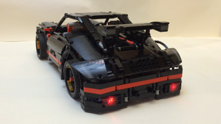
Occasionally, LEGO ends production of a set early or updates one mid-production because it realises it has made a design mistake. And sometimes, especially in Technic sets, an AFOL finds a better way of achieving a technical goal that LEGO has missed. Those situations are not what this post is about. This thread is to discuss LEGO's bizarre design decisions that must have been obviously weird to the designers... but they went ahead with anyway. Here's an example I came across recently when writing an article for Brickset: the mech's hands in set 71640 Iron Man Mech. Pretty much every review of this set including Jang's has questioned why the mech has a protrusion from the little finger side of the palm. You can see it in the mech's left hand in the picture above. It looks out of place and serves no purpose. Why didn't the designers use two 2 x 1 plates, one with a wheel attachment for the thumb and one without? I am aware that LEGO's designers have to operate within constraints, but it would have only added 2 to the parts count (one for each hand) and negligibly more to the cost. It is no less robust than the 2 x 2 plate with two wheel attachments, so why? If you're wondering what the hand would look like without the superfluous attachment, here's my mod: Any ideas why LEGO didn't do this? Also, what build decisions by LEGO seem strange to you?
-
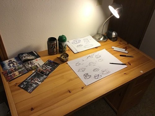
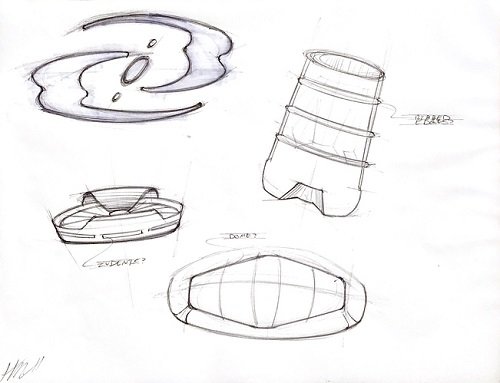
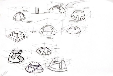
First Helryx Canister Design update! Round 1 Sketches Overview Hi everyone! I’ve created this topic to post progress of the Helryx canisters that I will be working on. This is my first topic ever created here so I really hope I did this correctly and am not violating any rules. I started this project on the TTV message boards, but have recently discovered this great community here & wanted to start interacting with y'all, seeing your work and sharing my own. My overall thoughts on this project & motivations on it can be found on the links below (which will bring you to said TTV message boards): Helryx Kickoff Helryx Canister Project Movitation Basically, the long+short of it is that I will be designing canisters/containers for each of the TTV canonization contest characters. I am really looking for lots of feedback to make this as top-quality as possible, so please let me know your thoughts! I’ve initially started sketching for the Helryx canister: Round 1 Sketch 1 Round 1 Sketch 2 I’m wanting to go with an ‘old-skool’ canister look, something from the likes of 2001-03. Obviously far from flushed out yet, been mostly working on the lid. I personally have my own thoughts about these designs but will keep them to myself for the moment - I want to hear yours! I really want community involvement/opinions to help make this the best it can possibly be. So please, comment, critique, criticize, and ask away! I’m looking to solicit as much feedback as possible while I keep sketching. Hoping to post again after another round of sketching (maybe 5ish days?) HM (edit: I know how annoying it can be to have to use imgur links to view someone's work/moc/etc. I tried to upload images directly to the post, but they appear to be too large - over the .1MB max size. If anyone knows how to help me out with this, that would be much appreciated Further edit: Was able to size down some of the images so that they are all (hopefully) displayed in the post without having to click on any links. Please let me know if this is working well, as I have lots more images to post haha)
-
 Hello :D I have made a few decal design I'd like to print or get printed, but I am not sure about what is the best way to do it. Is it better to do it at home? Or is there services I can use? (I live in the UK, in case you have specific services to recommend) Most services online assume you want to print a large number of the same sticker, but it's not my case. I've seen also many people use the "laser printer" technique to print their own stickers at home. Do they turn out durable? Do they have good quality, is the dithering noticeable? In the past I had stickers printed on a PVC sticker sheet, but they were too think and didn't stick enough, so over a few hours they'd just come off round surfaces like minifigure heads. Also, they were very easily scratched, which is not great... If you don't mind sharing photos of your own custom decals, it'd be greatly appreciated! Thanks :)
 -
 I started this project because I wanted to share my experiences building various offroad models over the last decade. This topic is meant to guide the builders with comparisments, suggestion and best building practices, It is however not a place to find already finished and perfected designs - that's up to you. Various aspects of the design of the vehicles will be split into several subgroups and explained in details. 1. Number of wheels First thing we need to know is how many wheels our design will have. Most common setups are as following: 4x4 Setup Advantages: 1. The simplest and most widely setup 2. Having only 4 wheels means lower weight and higher performance 3. Higher manoeuverability 4. Simple suspension and driveline design Disadvantages: 1. With only 4 wheels the suspension has to be designed to be as flexible as possible to get the most out of the wheels 2. In a case of a mechanical failure of a single wheel, the whole model's performance is greatly affected 6x6 Setup with double rear axles Advantages: 1. Two rear axle provide more traction area, especially when going uphill 2. Usually 6x6 vehicles are longer than 4x4 and therefore less likely to tip over 3. Since the front and second axle are usually closer than in 4x4 setup, there is less ground clearance needed between them 4. Greater redundancy in a case of a mechanical failure Disadvantages: 1. Lower manoeuverability due to a longer wheelbase even with rear wheel steering 2. More complex driveline and suspension design is required 8x8 or more wheels setup Advantages: 1. Having 8 or more allows for much greater traction area 2. Ability to drive over ditches 3. Because wheels are usually much closer there is much less chances of getting stuck on top of an obstacle 4. Excellent redundancy in a case of a mechanical failure 5. Better weight distribution 6. Less suspension travel required per each wheel as with 4x4 or 6x6 and hence better stability Disadvantages: 1. Lower manoeuverability even with rear wheel steering 2. Powering 8 or more requires a very complex driveline 3. Depending on a driveline, combined torque required for powering all 8 wheels can destroy gears if a single wheel gets stuck 2. Type of wheels and tyres Now that we decided on how many wheels we want for our offroad beast, we have to look into what type of tyres and wheels we want to use. I will hereby cover only the bigger types of tyres and wheels. 1. 94.8x44R Advantages: 1. Low weight 2. Good thread design 3. Low rolling resistance Disadvantages: 1. Low traction, these tyres are prone to slip on the rim at high loads 2. Due to its rounded shape the tyres tend to slide off obstacles when crawling over them 2. 94.3x38R Advantages: 1. Low weight 2. Medium traction 3. Low rolling resistance 4. Realistic design and proportions Disadvantages: 1. Shallow thread pattern 2. These tyres are very hard and don't adjust to the terrain 3. 107x44R Advantages: 1. Low weight 2. Medium traction 3. Very deep thread 4. Currently largest tyres by diameter Disadvantages: 1. High rolling restistance and vibrations due to the thread pattern 2. These tyres are a bit hard and don't adjust to the terrain 4. Power Puller tyres Advantages: 1. High traction 2. Good thread 3. Largest Lego tyres ever produced 4. Deep wheel offset Disadvantages: 1. High weight 2. Hard to use, they require complex hub assemblies 3. Very rare and expensive 5. Outdoor challenger wheels Advantages: 1. Very high traction 2. Very good thread pattern 3. Deep wheel offset 4. Over 7 studs of space inside the wheel Disadvantages: 1. High weight 2. Hard to attach to the standard axles 3. They require a lot of torque to use them at their full potential. 6. Tumbler wheels Advantages: 1. Low weight 2. High traction 3. Very flexible Disadvantages: 1. Low thread pattern 2. Small size 3. Expensive For the 94.8x44R. 94.3x38R and 107x44R tyres we have a choice of two wheels: 1. Racing wheel large Advantages: 1. Good mounting option with axlehole and pinhole 2. Available in multiple colours 3. Cheap Disadvantages: 1. No inside wheel offset means steering pivot point can't be placed inside the wheel. 1. Futuristic wheel Advantages: 1. Deep wheel offset allows us to place steering pivot point inside or closer to the wheel than racing wheel large 2. Slightly larger wheel size stops the 94.8x44R tyre from slipping on the rim Disadvantages: 1. Limited mounting options, with only one axlehole 2. Hard to find 3. Hubs Now that we have our wheels and tyres we need a way to mount and power them. Here are the most common currently available options: 1. New standard ungeared CV hubs These hubs are usually driven by the CV joint counterpart which pops inside Advantages: 1. Low steering pivot offset - usually at the edge of the tyre: 2. Firm wheel mounting 3. Readily available, easy to use and to build on. Disadvantages: 1. Low operating angle - the CV joint can operate to a maximum of about 30 degrees, which limits steering angle. 2. Very low torque transfer - the CV joints are prone to deforming and popping out even with low torque applies to them 3. Low ground clearance 2. Old ungeared CV hubs Advantages: 1. Low steering pivot offset - usually at the edge of the tyre 2. Firm wheel mounting 3. Better ground clearance than newer hubs Disadvantages: 1. Very low operating angle - the CV joint can operate to a maximum of about 25 degrees, which limits steering angle. 2. Very low torque transfer - the CV joints are prone to deforming and popping out even with low torque applies to them 3. Hard to find and expensive 4. No other mounting points than 4 ball joints 3. Built cardan ungeared hubs Example of a hub using a cardan joint to directly transfer the power to the wheel Advantages: 1. Low steering pivot offset - usually at the edge of the tyre 2. Easy to build 3. Can transfer higher torque than a CV joint 4. Higher steering angle Disadvantages: 1. Mounting relies only on the axle and is not as firm as standard hubs 2. Not capable of transferring high torque to the wheels 3. Low ground clearance 4. Standard portal hubs Advantages: 1. Easy to use and to build on. 2. Can transfer very high torque to the wheels when using 8z and 24Z gear combination 3. High steering angle 4. High ground clearance 5. Firm wheel mounting Disadvantages: 1. Very high steering pivot offset - requires stronger steering mechanisms and more fender space for wheel to swing 5. Built portal hubs Advantages: 1. Easy to build. 2. Can transfer very high torque to the wheels when using 8z and 24Z gear combination 3. High steering angle 4. Higher ground clearance than standard portal hubs 5. Low steering pivot offset when using futuristic wheels Disadvantages: 1. Wheels are mounted and held only by one axle, not as firm as standard hubs 2. Hub relies on friction of the components to keep it together, which can slide apart after prolonged use 6. Built planetary hub Advantages: 1. Highest gear ratio of all other hubs, 1:4 2. Firm wheel mounting when using futuristic of power puller wheels 3. High steering angle 4. Lower steering offset than standard portal hubs Disadvantages: 1. Requires old turntable, futuristic or power puller wheels for best results - all are hard to find 2. High number of moving gears 3. Least efficient due to the high friction caused by the large surface contact area and number of moving gears 4. Suspension Suspension is the mechanism that will keep our model's wheels in contact to the ground and will be supporting most of its weight. Most of the designs cover 4x4's Following factors determine the type of suspension system we will use: 1. Weight of the model - The heavier the model, the stronger the suspension components have to be 2. Speed - Faster models require more responsive suspension systems with low unsprung weight 3. Flexibility - The higher the obstacles you want to climb over the more flex and/or wheel travel suspension has to provide 1. No suspension I have yet to see and offroad vehicle without any type of suspension (except for maybe 42070, 42081 and 42082), but I will list my opinion regardless: Advantages: 1. Simple design - having no suspension simplifies our design...and that's about it Disadvantages: 1. No flex over terrain means, there are only 3 wheels at once touching the ground 2. Low stability 3. Poor weight distribution 4. No shock absorption at high speeds 2. Pendular suspension This is the simplest suspension you can put on your vehicle. It basically means one or more of your axles are free to swing about. When using this suspension I suggest using the small turntable where drive axle enters the axle. This will keep the drive axle from carrying the weight of the model, which causes unnecessary friction. 42030 is a typical example of this suspension system. Advantages: 1. Simple, robust design 2. Using this suspension on both axles can give the model very high flexibility 3. If there are no springs used, the model can have perfect weight distribution on left and right wheel Disadvantages: 1. Large unsprung weight, poor responsivness at high speeds 2. No shock absorption means this suspension is not suitable for high speeds 2. When using on one axle, the stability of the whole model relies on the unsuspended axle. 3. When using pendular suspension on both axles springs or a transfer mechanism are required to keep the model upright 3. Single torque tube suspension This suspension became available with the release of the 8110 Unimog. Best examples of this suspension are 8110, 9398 and 41999. It is the simplest suspension which also allows for vertical suspension movement. Advantages: 1. Simple, robust design 2. Universal joints can be placed inside the ball joint, allowing power to be transferred to the axle 3. Easy to implement Disadvantages: 1. Large unsprung weight, poor responsivness at high speeds 2. Axle requires a some kind of a linkage system to keep it cenetred (panhard or parallel links as seen above). 3. Using this suspension on the front axle usually results in negative caster angle which causes higher rolling resistance 4. When used on rear drive axle, the suspension has the tendency to cause oscillate, especially with soft suspension and high power 4. Hard to connect springs to the chassis 4. Double torque tube suspension This is an evolution of the single torque tube suspension, which uses two ball joints to drive each wheel side respectively. It is my own original idea. Advantages: 1. Simple, robust design 2. Universal joints can be placed inside the ball joint, allowing power to be transferred to the axle 3. Easy to implement 4. Self-cenetring, since axles are connected in the center there is no need for linkages to center it 5. Can carry power to each wheel side independently 6. Drive torque compensation Disadvantages: 1. Large unsprung weight, poor responsivness at high speeds 2. Using this suspension on the front axle usually results in negative caster angle which causes higher rolling resistance 3. When used on rear drive axle, the suspension has the tendency to cause oscillate, especially with soft suspension and high power 4. Hard to connect springs to the chassis 5. Parallel floating axle This suspension uses linkages which keep the axle parallel to the chassis of the model. For best functionality and reliability the lengths of all links and that of the double cardan joint should be equal. Also all the linkages and drive axles should be parallel. Advantages: 1. Keeping the axle parallel to the chassis reduces the oscillations effect 2. Better responsivness compared to the torque tubes 3. Neutral caster angle when used on front axles. 4. Self cenetring when using A arm as upper link or 4 link setup 5. Can be configured to carry power to each wheel side independently 6. If configured to carry power to each wheel side independently the drive torque can be compensated. 7. Easy to connect spring to the chassis Disadvantages: 1. High unsprung weight, less responsive at high speeds 2. Increased mechanical complexity, double cardan joints required to carry the power to the axle 6. Half axle independent suspension This is the simplest independent suspension you can build. Best example of such suspension are Tatra and Pinzgauer trucks. Advantages: 1. Independent suspension with low unspring weight, suitable for high speed 2. Robust design with low number of moving parts 3. Easy to connect spring to the chassis Disadvantages: 1. Changes of the caster angle as the wheels travel up and down 2. Hard to implement a drive system that does not carry the weight of the vehicle 3. Hard to implement steering system 4. Wheels tend to drag sideways on the ground when suspension travels up and down, reducing efficiency 7. Trailing arm parallel independent suspension Personally I have not used this suspension yet, but I did use a normal trailing arm suspension which does not keep the hubs parallel. Normal trailing arm suspension which does not keep the hubs parallel acts similarly to torque tube suspension. For the prallel version of the trailing suspension I imagine the following: Advantages: 1. Independent suspension with low unspring weight, suitable for high speed 2. Robust design with low number of moving parts 3. Long links allow for high suspension travel 4. Very easy to connect spring to the chassis 5. Can be configured to carry power to each wheel side independently Disadvantages: 1. Hard to keep the wheels from sagging under the weight of the model. 2. Difficult to transfer power to the wheels 8. Double wishbone suspension This suspension uses two A-shaped arms to keep the wheel hubs in place. As of late it's my favourite suspension system due to: Advantages: 1. Independent suspension with low unspring weight, suitable for high speed 2. Very customizable design with lots of adjustable characteristics (suspension arm lengths, caster angle, camber angle, steering geometries) 3. When build correctly it is far more robust than live axle suspension 4. Increased ground clearance compared to live axle suspension, especially when used with portal hubs 5. Can be configured to carry power to each wheel side independently 6. Extremely easy mounting of springs 7. Very stable compared to live axles 8. Frame holding the suspension can be part of the chassis, therebye lowering the center of gravity Disadvantages: 1. More moving parts as live axle suspension, increased mechanical complexity 2. Limited wheel travel - Lego wishbones allow a max. of around 25 degrees of suspension angle 9. Multi-link suspension To be updated when I build my first multi-link offroad suspension. I can assume the following characteristics: 1. Independent suspension with low unspuing weight, suitable for high speed 2. Extremely customizable design with lots of adjustable charactersitics (suspension arm lengths, caster angle, camber angle, steering geometries, virtual pivot point) 3. Large steering pivot point compensation 4. Increased ground clearance compared to live axle suspension, especially when used with portal hubs 5. Can be configured to carry power to each wheel side independently 6. Very stable compared to live axles 7. Frame holding the suspension can be part of the chassis, thereby lowering the center of gravity Disadvantages: 1. Very high amount of moving parts, increased mechanical complexity 2. Limited wheel travel - Lego wishbones allow a max. of around 25 degrees of suspension angle 3. Hard to connect springs to the chassis 10. Spring types Listed below are the most common types of springs available: 6.5L Soft shock absorber Advantages: 1. Small, easy to implement Disadvantages: 1. One stud of suspension travel 2. Low spring rate, can't support heavy models 6.5L Hard shock absorber 1. Small, easy to implement 2. High spring rate, can support heavy models Disadvantages: 1. One stud of suspension travel 9L soft shock absorber When using 9L shock absorbers I suggest you do not use the default offset upper attachment point, but use an in-line attachment point instead. This will reduce the friction and allow for better high speed performance Example: Advantages: 1. Two studs of suspension travel 2. More attachment possibilities than 6.5 L shock absorber Disadvantages: 1. Default attachment points create friction 2. Low spring rate, can't support heavy models 9L hard shock absorber Advantages: 1. Two studs of suspension travel 2. More attachment possibilities than 6.5 L shock absorber 3. High spring rate, can support heavy models Disadvantages: 1. Default attachment points create friction 2. Rare and expensive 11. Attaching springs to live axles If we start with basics, the first things we have to check is how position of springs affects suspension of live axles. The closer you place the springs together, the more flex the suspension will have, but it will also be less stable: I suggest you to keep springs at a distance of around 1/2 of the total model width. When placing springs you should keep them in-line with the wheel bearing in order to reduce friction. First example of bad spring placements: And example of good spring placement: When using multiple springs make sure to place them symmetrically centrred to the wheel hub: When attaching springs to torque tube suspension, you have to allow springs to tilt in two planes: You can also attach the springs to the suspension links to increase suspension travel. This technique is especially common on Trophy Trucks: 12. Attaching springs to independent suspension Independent suspension allows for much more flexible spring placement. Generally the closer you attach the spring to the main suspension arm pivot, the higher spring travel you get, but lower suspension force. Examples going from the hardest suspension with low travel to the softest with high travel: You can also attach springs inside the suspension arms: Or horizontally: As with the live axles make sure springs are in the center of the wishbones. Example of good placements: And an example of bad spring placement, which causes excessive friction and suspension binding: 5. Steering Steering is the system which allows our model to change direction. Generally there are two types of steering system used: 1. Skid steering Advantages: 1. Very simple to implement and control with two separate motors for left and right sided wheels. 2. Does not require a dedicated steering motor Disadvantages: 1. Not efficient, since wheels have to skid to steer 2. Power had to be reduced or even reversed in order to steer. 3. Not very accurate 4. Not very effective offroad 2. Classical steering with steerable wheels Advantages: 1. Efficient, with minimum loss of speed 2. Accurate 3. Does not reduce the power of the drive motors 4. Can be used in front, rear or all axles for tight steering radius or crab steering 5. Effective offroad Disadvantages: 1. Requires more complex hub assemblies 2. For best steering accuracy you need a dedicated servo motor. Examples of a simple classical steering system for live axles 1. Parallel steering system for live axles Here both hubs are always parallel. Position of the steering in the front or rear rack has no affect on the steering. Advantages: 1. Very simple and robust 2. Easy to build Disadvantages: 1. No Ackermann steering geometry 2. Steering rack moves inwards as it steers, requiring more space. 2. Ackermann steering system for live axles This system allows the hubs to steer at different rates. The steering arms are offset inside so they form a virtual steering point where at the point where lines meet. Advantages: 1. Better steering performance Disadvantages: 1. More complex assembly 2. Steering rack moves inwards as it steers, requiring more space. 3. Steering system with diagonal linkages This system acts similar as Ackermann steering system by using diagonal steering links. Advantages: 1. Better steering performance 2. Steering rack only has to move in one direction without sideways movements 3. Can be configured to be used in front or the rear of the axle. Disadvantages: 1. More complex assembly 4. Simple steering system for independent suspension 1. Very simple and robust 2. Easy to build 3. Can be even more robust when using double steering racks and links 4. Steering rack only has to move in one direction without sideways movements Disadvantages: 1. No Ackermann steering geometry 5. Ackermann steering system for independent suspension Advantages: 1. Better steering performance 2. Steering rack only has to move in one direction without sideways movements Disadvantages: 1. More complex assembly, less robust. 3. General steering tips 1. When using independent suspension always make sure your links are paralel to the suspension arms, otherwise you may end up with wheels which are not parallel and are causing excessive friction: 2. When using standard portal hubs make sure your steering system is robust enough to deal with the forces generated by wheel driving into obstacles. 3. If possible use servo motors which allow for high steering precision and return to center. They are especially useful at high speed models. 4. Most efficient way to steer the wheels is using the steering racks. 5. Build axles in such way they have positive caster angle, example for direction of travel from right to left. This will self-center your wheels and reduce rolling resistance. 6. Drivelines Drivelines are the responsible for transferring the power from the motors to the wheels. There are various drivelines you can build, here I listed few with their characteristics: Driveline types 1. Permanent 4x4 Advantages: 1. Simple, centralized, low mechanical complexity 2. Wheels are always powered, great offroad performance 3. Light weight Disadvantages: 1. Poor steering radius 2. Tyres have to skid when steering, lowering efficiency of the model 2. 4x4 with open differentials Typical example of this driveline is 42070 Advantages: 1. Differentials allow the wheels to so spin at different rates when steering 2. Very efficient since wheels don't have to skid when steering Disadvantages: 1. If one wheel loses traction, all the power is transfereed to it, poor offroad performance 3. 4x4 with lockable differentials Advantages: 1. Differentials allow the wheels to so spin at different rates when steering 2. Very efficient since wheels don't have to skid when steering 3. All differentials can be locked, so wheels are powered for great offroad performance Disadvantages: 1. Higher mechanical complexity 2. Dedicated motor is required to actuate differential locks, higher weight 4. Axle mounted motors Typical example of this driveline are 9398 and 41999. Advantages: 1. Differentials allow the wheels to so spin at different rates when steering 2. Very efficient since wheels don't have to skid when steering 3. If one wheel gets off the ground the second axle can still pull/push the model. Disadvantages: 1. Higher mechanical complexity 2. Usually the rear axle motor is more loaded than the front, especially when climbing uphill, the motors can't "help" each other. 3. Worse offroad performance than permanent 4x4 5. H drive: This is my favourite driveline due to the following reasons: Advantages: 1. Motors allow the wheels to so spin at different rates when steering 2. Model can skid steer 3. Very efficient since wheels don't have to skid when steering normally 4. Having 2 drivelines allows you to carry more torque to the wheels 5. Redundancy, even if one drive fails the model can still move 6. Wheels are always powered, great offroad performance Disadvantages: 1. Higher mechanical complexity 2. Slightly higher weight 6. Wheel motor drive Each motor powers a wheel independently. Advantages: 1. Motors allow the wheels to so spin at different rates when steering 2. Model can skid steer 3. Very efficient since wheels don't have to skid when steering normally 4. Redundancy, even if one or more motors fails the model can still move 6. Lower mechanical complexity Disadvantages: 1. Motors can't "help" each other 2. Higher weight due to a higher motor count Transferring power axially When transferring power via axles, you can reduce the flex by using connectors instead of simple "bare" axle: Use axles with stops to prevent them from sliding out of gears: Where possible always brace tooth gears from both sides: Transferring power at an angle Where pairs of U joints are used, make sure to align them to eliminate vibrations: Brick built CV joint which can transfer high torque at over 30 degrees angle Brick built cardan joint which can transfer extremely high torque up to 15 degrees angle Brick built flexible drive which can transfer medium high torque, extract and retract, suitable for low angles Transferring power perpendicularly The following perpendicular gearboxes are the best suitable for transferring high torque Avoid knob and worm gears, because they waste energy Gearboxes In my models I generally use the following gearboxes: 1:3 differential gearbox Advantages: 1. Very high gear ratio between low and high gear, 1:3 2. Capable of transferring high torque 3. Very efficient since only 2 gears are used at any time Disadvantages: 1. Takes a lot of space 2. This gearbox requires a good housing to brace the gears properly Compact two speed gearbox Advantages: 1. High gear ratio between low and high gear, 1:2,77 2. Capable of transferring high torque 3. Very efficient since only 2 gears are used at any time 4. Very compact design Disadvantages: 1. Requires two of the rare 20 tooth clutch gears 2. More complex shifter assembly. Diagonal gearbox Advantages: 1. High number of gears 2. High gear ratio possible, over 4:1 2. Capable of transferring high torque 3. Very efficient since only 2 gears are used at any time Disadvantages: 1. Takes a lot of space 2. Input and output axles are not parallel. 3. A complex shifting assembly is required for sequential operation. Driveline effect on suspension Transferring torque on the wheels can affect the suspension, especially when live axles are used. The following photo shows how the torque causes one side of the axle to push down and the other to lift up: In order to minimize this effect I suggest the following: 1. Make sure to have most if not all the downgearing inside the axles, so you do not need high torque going to the axles. 2. Make sure your models have a low center of gravity 3. You can eliminate this effect by using two counte rotating axles which cancel each other's torque, example below: 7. Motors and control Following are the most common types of motors used for Lego models. You can find more info here: http://www.philohome.com/motors/motorcomp.htm My personal favourites are L and RC motors due to the balanced output speed to torque ration and great mounting options. 1. PF-M Advantages: 1. High speed output 2. Smallest available motor 3. Cheap and available Disadvantages: 1. Low torque 2. Poor mounting options 2. PF-L Advantages: 1. High speed output 2. High torque 3. Cheap and available 4. Great mounting options Disadvantages: 1. Odd shape 3. PF-XL Advantages: 1. Very high torque 3. Cheap and available 4. Good mounting options Disadvantages: 1. Slow speed output 2. Large form factor 4. PF-Servo Advantages: 1. Very high torque 2. Very precise output with 15 positions 3. Good mounting options Disadvantages: 1. Slow speed output 2. Output axle can move a max of 180 degrees 3. Large form factor 4. Hard to find 5. 9V-RC motor Advantages: 1. Most oowerful Lego motor 2. Very high speed output 3. Good mounting options 4. Two output axles with different gearing ratios 5. Drive axles can pass through the motor Disadvantages: 1. Low output torque 2. Low efficiency 3. Power hungry 4. Odd form factor 5. Hard to find and expensive Power options 1. PF - AA battery box Advantages: 1. High capacity 2. Good mounting options 3. Works with rechargeable batteries, but with lower performance 4. Cheap and easy to find Disadvantages: 1. 750mA current limit - not enough to fully power RC motor 2. Heavy 3. Has to be removed and opened to replace batteries 4. Wasteful 5. Odd form factor 2. PF - LiPo battery box Advantages: 1. Small form factor 2. Light weight 3. Easy to recharge Disadvantages: 1. 750mA current limit - not enough to fully power RC motor 2. Low capacity 3. Studded design 4. Expensive and hard to find 3. RC control unit Advantages: 1. No current limit - can power 2RC motors at once 2. 3 Power levels 3. Has integrated steering output with 7 positions 4. Good mounting options 5. Easy battery replacement 6. Radio based control Disadvantages: 1. Poor quality, prone to breaking 2. Limited angle (45 degrees) and torque from the steering output 3. Has to be removed and opened to replace batteries 4. Very large form factor 5. Expensive and hard to find 6. Heavy 7. Required dedicated antennas and remote Control options 1. PF receiver and controller Advantages: 1. Receiver is easy to integrate into the model 2. Controllers have physical feedback 3. Cheap and easy to find Disadvantages: 1. IR based, low range, useless outside 2. Lack of PWM motor control, unless using train controller which is awkward to use 3. Odd form factor for use with steering 2. RC control unit See above 3. Third party options such as BuWizz and Sbrick Advantages: 1. Smaller form factors, easy to integrate into model 2. More outputs than PF system 3. Smooth control of motors 4. High range thanks to Bluetooth control 5. Higher power available with BuWizz 6. Customizable profiles Disadvantages: 1. Smart device is required 2. No physical feedback 3. Sbrick is limited by PF battery box 4. Price 8. Chassis Chasis is the backbone of your model which olds everything together. For chassis I suggest you to use the following components in order to make it strong and robust enough to deal with the stresses involved when crawling or driving at high speed: Some flex in the chassis might be a good thing to improve offroad capability, but only if id does not affect the driveline and cause friction on the drive axles. Remeember to use diagonal support, since triangles are the strongest shapes. You can also use panels and motors as structural support. Interlocking your chassis will keep it from slipping apart. For good examples of chassis designs I suggest you check the instructions for 9398 and 42083.
 -
Hi Everybody!!!! I m really new to designing so I kind of need some help!!!! PLeaaaase :) I basically bought some instructions of a moc and was not happy with it in general. did not like the details as well as the underlying structure so decided to give it a go and downloaded studio! I m really excited and been working on the project at least a month now and must say I m handling it really well! BUT this particular set nets nets strings tubes that need flexing etc. That is where I got a problem!!! For example nets are not even available on the program and tubes are really hard to manipulate and connect... I did a search on you tube and in the forum but did not find an answer... I would really appreciate any help or advice!!!
-
 Dear readers, For a new project that started a while back (about a year ago), I was investigating a certain track configuration for a tracked vehicle. It pointed out that I needed a lot of ground clearance from the track wheel, but the track wheel could not be two studs wide: the tracked vehicle is only 15 studs wide and a lots of gears, motors and linkages need to be in between. As you can see, the standard wheel above is two studs wide due to a ring of 1/2 a stud that supports the track. This ring is not always necessary. In fact, the tracks barely even touch this ring under normal driving. A lot of you will recognize the difficulty with this wheel: it protrudes half a stud to both sides. In many designs, the number of horizontal studs is uneven: an M motor, XL motor, frames, differential, everything has an uneven width when measured in studs. This enables a symmetrical design as Lego Technic has no beams with even lengths (only 3, 5, 7, 9 ..). That's why many Technic designs of this day are an uneven number of studs wide. This is in contrary to the olden days, where all Technic components and widths were even. Check for example the old style liftarms, differential, frames, motors and even battery boxes. With this theory lesson over, it is easy to see why this track sprocket introduces a problem: when the wheel is mounted in the uneven Technic system (to get a nice symmetrical design with uneven Technic beams), the wheel size is even! So the wheel can not be connected to a liftarm at the place where the axle connects to the wheel. There needs to be a distance of 1 stud to any supporting liftarm. This is mostly done with a bush or a 3L thick liftarm. This also means that to mount this sprocket very strongly, the minimum width of the structure (when fit in an uneven system) is 5 studs. Then I started thinking: how nice would it be if there would be NO distance to any supporting liftarm? In that case, the sprocket has to be only 1 stud thick and the supporting structure is only 3 studs wide. Also, the support ring has to go. This is an enormous space saver when the maximum width of your vehicle is 15 studs.. I decided to draw the part in Solidworks and print it with my own 3D printer. Out of curiosity, I checked GrabCad to check whether someone got the same idea too. To my amazement, somebody had already tried this part, with the internals to be the 40 teeth gear. This is done with a reason. A standard 3D printer is generally very bad at printing axle holes. If you draw the outline of a standard Lego Technic part (that has a nice axle hole) into your 3D printed part, the part will be connected firmly inside the model(nice) while the axle is inserted into a Technic part, so no troubles with cracking plastic will occur. In short, I printed that part. It didn't work. (See image below). It turned out that every 3D printer is a little different. A tiny offset can cause a diameter difference, which then will cause friction, because the track doesn't fit around. The wheel needs to be perfect to make the solution work. That's why I decided to design my own custom sprocket wheel from scratch. This was my first 'from scratch' attempt. As you can see, the pin and axle holes do not have great quality. A revised 3D design is in the image below. As you can see, there is a large hole in the middle. This hole fits two 4185 pulley wheels (shown right) very tight. This means the vehicle is connected to a nice and round axle hole, while the 3D printed part is also fit very well to the vehicle. The sprocket diameter is not arbitrary as the number of 'lobes' is fixed: there are no half lobes, otherwise the wheel won't work.. That means that for the same tracks, a limited number of wheel diameters exist. As you can see, there is a slight ring in the 1 stud wide sprocket wheel, not all track support is gone. The 3D printed results: I was really happy with the quality of this wheel, the drawbacks from 3D printing don't show up and the wheel is very strong and straight. In the image below, is is visible that the tracks fit very smoothly around without additional friction. It is also visible that the wheel is just as wide as two pulley wheels, so one stud. I was so amazed when the 42095 set was launched. There was my not-published-about part, exactly the same size, in a real Technic model! And now there will be 4 DBG ones in the 42100 Liebherr, which will drop the price. There is one 'slight' drawback though. My 3D printed wheel is only one stud wide, needing only a frame of 3 studs wide to support it. The new 42100 sprocket wheel has the 1/2 stud ring protruding out of it on both sides, taking the drawback of the old wheel onto the new wheel. That's a pity. It could have been so nice. Then comes the question: why would you 3D print parts? That's cheating. And I agree. It is cheating. I never do this in my models. You are allowed to check my YouTube. I even built of a 3D printed way of getting three axles through a Lego Technic turntable but never used the solution as I do like pure models. Then, why am I doing it now? Because currently, I'm using Lego Technic as a strong platform for a scale model that requires 100% of the quality of Lego Technic, but cannot do without adding custom parts. Even the most skilled builder cannot work his way round sprocket wheels that don't exist. That's why I see it as an engineering project, and from that prospect, creating your own parts (when all else fails or doesn't exist!!) does not show lack of skill but broadness of view.. Surprisingly, some other minds thought alike and brought a Lego Technic wheel of the same size on the market. Too bad.. Let's start building and stay thinking!
 -
 So, I've been pretty miffed about dolls since they came out. I actually was pretty interested in the friends set as a concept as there is a market for it, I just think the dolls were a misstep. Elves, on the otherhand, made dolls even more of a misstep, turning it into a tragedy. For background, I love fantasy, and I love Dungeons & Dragons, and Tolkien, you get the idea. For a while, we've been rather deprived of a proper fantasy setting, and I feel elves could have alleviated to downright fixing this problem. However, I feel that the potential of the theme was diminished when they decided that Dolls and the more 'cutesy' molds would be an integral part of the theme. I don't dislike, in fact I heavily approve of the color decisions, both from a moc perspective, and a theming one to depict a more fantastical and fey fantasy setting. Hell, I'll probably pick up these sets at some point when depicting my D&D groups going through the feywilds! The hair pieces they went with are perfect for stuff like Eldarin, Wood elves, and high elves, even more D&D style gnomes in their younger years (if you haven't picked up on it yet, I'm always hoping Hasbro sells of Wizards of the Coast so that LEGO has an excuse to pick up D&D as a theme!). But going back to the dolls themselves, they lack a great amount of customization (I'm pretty sure the forums have threads on this already), and I feel were a wasted opportunity for more minifigure designs: heads, torsos, legs, accessories, all muddled by introducing the dolls. At least the hair is compatible. I understand that LEGO is trying to vie for a share in the girl's toy market, but I feel that it's not the best way to go about it. For one, they isolate a lot of the LEGO market by using the dolls in the first place, as I know some AFOLs don't like using them as they have very little range of setting or look. Why did LEGO decided to place dolls in one corner of the market when they could have made a really appealing all-rounder simply by using regular minifigures and more interesting molds? Do the dolls have more fans than I give credit for? So, I guess the reason for posting this is, do you think LEGO will come out with a new fantasy set soon? I know Nexo Knights had a really small wave that probably marks its end (didn't keep up with news if it was cancelled or not), and how long is Elves lasting? Are they going to release more Tolkien universe sets with the new Netflix show? Are they ever going to make a new original IP or revive Castle in the near future? I'm not caught up in the current rumor mill or what's been revealed for next year, so I'm wondering if any of this has been addressed recently.
 -
Hi everyone I'm happy to share my second MOC which I have been working on over the last 5 months. I build the MOC with BrickLink Studio 2.0 and used the new Eyesight Render for my images. The MoMA - Museum of Modern Art is a MOC modular building inspired by modern architecture. The MOC has several highlights like a staircase fully made of glass bricks or a full-functional elevator on the backside. The MOC includes many of advanced building techniques and has a high level of details on each floor. It’s built on two standard 32 x 32 base plate and includes 18 minifigures, 28 paintings and 8 sculptures. The dimensions of building are 10.2x20.6x18.2 inches (width x length x height) or 26 x 52.3x46.2 cm. Level 1 - Entrance – Museum Store – Art Gallery The first floor contains the main entrance of the museum with a cash desk and a small design store for gifts and souvenir. The art gallery on the ground floor contains 6 paintings and 3 sculptures. Minifigures Older couple interested in modern art Museum employee operates the cash desk Store seller serves a customer Art-hipster buys a souvenir Security guard enjoying his coffee break Art Student looks at the sculpture Tourist interested in art Level 2 – Restroom – Art Gallery On the second floor there is a toilet for visitors and a gallery with a view into the ground floor. The art gallery on the second floor contains 11 paintings and 1 sculpture. Minifigures Artist looking for new inspiration Art interested friends couple Level 3 – Security Control Room – Art Gallery – Art Terrace On the third floor there is a security control room to monitor the valuable paintings and sculptures. A highlight in the art gallery in this floor is the large flower sculpture. A small outdoor area offers further space for abstract sculptures. The art gallery on the second floor contains 5 paintings and 3 sculptures. Minifigures Security guard what happens in the museum Father inspires his daughter for art Art lecturer during his lunch break Level 4 – Viewing platform – Art Café On the fourth floor there is a small Viewing platform on the top of the building. In the cozy art café, visitors can enjoy a piece of cake and coffee while enjoying the view through the large panorama window. Minifigures Barista conjures a work of art from every coffee. Visitor enjoys her coffee after an exciting museum visit Visitor treats herself to a cool drink and a slice of pizza Thanks very much for reading and I hope you like my second MOC. There are more pictures on Bricksafe and feel free to support my MOC on Rebrickable and let me know what you think about. At the moment I am building my MOC with real Lego bricks. As soon as possible I will post any photos of the real lego building.
-
Hello Eurobricks! First time poster here. Im in the midst of making my own model of a spaceship from an older anime. (3D rendering of the ship by Renan Longatti https://www.artstation.com/artwork/EW1KN ) Now, i've made the main bulk of the engines and moved on to the cockpit part - my problem is i cannot figure out to make a sturdy enough hinge design for the various 'flappy' parts on the engine cover, while keeping the scale uniform with the stationary parts without having too much bulk ie. making the engines too bulky/wide, and I'd hate to remake the model for scaling problems again (Have already done this once so far) I've troubleshooted on my own for a weeks time now and think i'm beginning to go blind for possibilities myself. I have a relatively clean model up on mecabricks that people can play with, and if someone could help i'd really appreciate it. Model on mecabricks: https://www.mecabricks.com/en/models/b82xKJ71a1z A final thing to keep in mind - my plan is to complete the model and buy all parts when done and assemble irl so everything have to be correctly put together(no cheating for 'looks' sake) Thanks in advance - feel free to ask for further info or otherwise, I'll reply asap :-)
-
Finished my last SWAT TEAM Lego Minifigures . Each Minifigure is made with a Custom Design and parts, I hope you like it!
-
I would like the Mixels balljoint cup 1x2 plates, but with the cup rotated 90 degrees for greater movement freedom. I could also use 1x2 plate Mixels balljoint cup with the cup on top like 11458 and one with cup on bottom like 24201 or 18677. Mixel cup one end, jumbo cup other end. Mixel ball one end, jumbo ball other end. I would also like a 1x2 plate (or more) with studs on top and bottom (no clutch side). What would you more experienced Lego builders want?
-
 I spend long periods away from home and my Lego bricks due to my work, so I end up doing a lot of design in computer with the likes of LDD, LDraw/bricksmith, and mecabricks. The problem is that none of these have any "physics" in them, I can't ever see how strong or stable the model is. So I end up spending hours agonising over the way the bricks are stacked, worrying over whether or not they will lock together solidly enough in real life. I also spend ages checking brick link and Lego bricks and pieces to make sure the pieces I use are available in the colours I choose, but that's another story. When I finally do treat myself and buy the bricks for one of my creations, they invariably fall apart. A couple of years back it was a 50 piece micro-scale particle detector that took 2 hours to get together and exploded at the slightest touch (and I do mean that literally, bits went flying all over the room!). My latest fiasco is a model of the Mercury-Redstone rocket, which I designed to go with the Lego Ideas Saturn V. It's just a stack of 2x2 round bricks with three axles inside due to it's height, yet despite my best efforts to put the axle transitions well inside bricks, the rocket easily falls apart into three neat chunks (one for each axle). So, what's the secret? When you design in computer do you care at all about how the model would behave in real life? And if you do care, do you have any tips on making sure that the model holds up well when physically built?
 -
This was built as part of the InnovaLUG collab, Ye Old Merry Battleground, for Brickfair Virginia.Check out the full collab here. Given the colorscheme and landscape, I thought this would fit well in Avalonia. I enjoyed getting to use some of our new sand green parts, and small castles/manors are always fun to build. There is no interior as when building this, Nordheim was still altogether and I was short on parts and time. Sir Ruari Leanin leads some of his soldiers out on a tax collecting tour. Meanwhile, some Forestmen take advantage of his leave-taking... There are a few more pictures on brickbuilt. Your comments and suggestions are always welcome
-
 Hello! This time I'd like to share my latest project: a drawing machine that is inspired by Joe Freedman's Wooden Cycloid. The LEGO version uses freestanding boxes that can be moved around the turntable. A slight change in position creates a different pattern. Further adjustment is possible by placing the drawing arm onto the different pins on either drive box or changing the position and distance of the pen. Placing one end of the arms further from the center can create a pattern up to 20cm in diameter. The variation possible with this setup makes it almost impossible to repeat exactly the same pattern. Now since I'm a huge fan of psychedelic music and digital art, I wanted to make the video resemble some of the artwork we always see at the outdoor parties. Without giving too much away, I'll let you grab a drink, turn the volume up and enjoy the video! Full write up with more images here. Thanks, Mik
 -
This is the 6th module of my large collab with John. You’ll be able to see it in person at Brickfair Virginia 2016. Previous modules: 1st, 2nd, 3rd, 4th, 5th. As with the other modules, the building has a full interior. Legopard inspired the cart. The Jarl of Nordheim resides in the large great-house that serves as the primary governmental building of the city. See more pictures on brickbult. Thanks for looking, I hope you enjoy
-
 Loosely based off a corvette design, I created this black and white supercar out of Lego. Driven by 2 l-motors and a servo placed all in same spot behind the seats. I know the engine should be in the front but whatever, like the look of it in the back Flickr: https://www.flickr.c...0963@N04/4b6LFN
 -
Hi guys today I'm gonna show my custom LEGO SWAT TEAM. You can see ALL the details in this video where I'm reviewing them. Hope you will enjoy it , PLEASE LIKE ANS SUBSCRIBE TO MY CHANNEL, thanks for supporting.
-
[MOC] Porsche 911
Lox Lego posted a topic in LEGO Technic, Mindstorms, Model Team and Scale Modeling
This custom creation was created with a variety of old and new Technic pieces for a different effect to the final build. Designed by an actual Porsche mechanic and myself. Original: Rework: FInal version:
-
Hi all, I've been doing a bit of brainstorming about what to do concerning the current state of affairs for trains on Lego Ideas, and while I am currently working on a couple different solutions of my own, I finally landed on an idea that would include all of you as well. A bit of friendly competition, all towards a common goal: a better/more appealing train set offering for Lego fans. So, I am proposing we start a set design contest here on Eurobricks!! (maybe even get it up on the front page?) The Parameters: -A complete train set, not a standalone car, engine, or track-side structure. Generally an engine, 2-3 rolling stock, and one structure. -A 1000 parts count maximum, which must include necessary PF elements and at least 20 pieces of track (standard oval). -A self-contained engine, meaning no rolling stock can carry necessary PF elements. -At least 2-3 "play features", not including the operation of the train itself. -At least one alternate build. (Alternate models do not have to meet the same requirements as the primary model) -Must use parts currently in production, however new/different colors of said parts can be used. Some Suggestions: -Come up with a few stories about what the minifigs included in the set could and would be doing. -Try to avoid using generic flat cars and wimpy helicopters. -Use 1-2 rare/unique colors that haven't appeared in a train set yet, like azure, purple, dark red, etc. -Try not to make your train too regionally specific by using road names such as GWR, LNER, UP, CN, etc. Color schemes may be mimicked though. -Develop a play feature that hasn't been used in a train set before. -Try to have each element of the set be as interesting on its own as it is with the rest of the set. I'm not sure how much time should be given to a contest like this, but I'd reckon about 30-90 days would be about right? Then, about 2-4 weeks for voting? The top 3-5 projects (depending on the amount of participants) could then be refined a bit before submitting to Lego Ideas. If this contest receives frontpage support, maybe some prizes could be awarded to the top finalists...? Let me know your thoughts on my proposition, and also who I need to contact to make this happen! Thanks for your time, ~M_Slug~
-
 Hi folks. I need some advice from people who have experience building large structures. I'm looking at building a GBC module that takes balls across a gap between two tables, that's high enough to walk under. I need a vertical lift of about 1.3m, and a horizontal travel of about 1m. Now, this would be by far the largest model I've ever undertaken, so my intention is to design the thing in LDraw before I buy anything. This means I can't see how sturdy the structure actually is, so I'm asking you all whether what I've designed so far is sensible. I've got two slightly different truss designs. One that I think would go better for the vertical parts, and one for the horizontal. Each is a single unit 16 studs in length, with the idea that you join as many units together as you need to get the length/height required. First, the vertical segment: And what three of them together look like: I feel that this truss is going to be strong in compression/tension, but all that space in the middle makes me nervous - is the 5x7 frame box going to be solid enough to make it strong in torsion as well? Next, the horizontal segment: And three of them together: This one I think would be quite resistant to bending in the up/down direction (exactly what you want for a horizontal beam supported at its ends), less so in the side/side direction, but also strong in compression/tension. This one would be somewhat heavier than the other - overkill? or is the extra strength warranted? I'd appreciate your thoughts on these two truss designs. If you want to see the .ldr file that these images came from, it's here. Regards Owen. P.S. If anybody wants to take these and make them into a tower crane for [TC8], go right ahead. EDIT: Yes, I know there are no triangles. I am relying on the rigidity provided by the 5x7 frames in place of diagonal bracing.
 -
Service Status: Still looking for somebody to perform this task. Hello, as the title states; I am for looking for somebody who can digitally design me a imperial base with a budget of $300 in total as well as create a list of bricks to purchase from bricklink so I can build it myself. I expect the model to be detailed, high quality, and look good. I never made any builds digitally so I'm not sure how I would be able to rebuild it from a online model but I'm sure you can help with that. Total build budget is $300. You get paid the remaining amount after cost of bricks. So for example, if the build costs $200 from the bricks, then you get $100 as payment. You may use any software as long as it can be easily reproduced physically. I think stud.io would be a good software to use as it links with bricklink to buy parts easily. Here are the specifications and features of the build. Also includes picture examples from similar MOCs and feedback on them. This document has been recently revised with more detail on 7/24, https://pastebin.com/9FDgvCRB Post here or PM me if you are interested in doing this service.
-
Hi everybody, With the new Alien: Convenant movie coming to cinemas this May, I wanted to pay tribute to the original Alien motion picture (1979) by building the space ship in which this sci-fi classic is set – the USCSS Nostromo. Since there are already some beautiful Lego designs of the Nostromo ship (the “towing vehicle”), I wanted to do something different. As Alien fans will know, in the first few minutes of the movie, a massive refinery is moving silently through open space. I would try building this ore refinery! I hope you like the result and thank you for your feedback and comments. A special shout-out goes to the Arvo Brothers, who did some amazing Alien designs. Their work and our mutual passion inspired me to start this first Lego project . The Lego Model: Bricks: 3'144 Scale: 1:42000 (approx.) Length: 55 cm (22 in) Width: 40 cm (16 in) Height: 38 cm (15 in) Weight: 3.4 kg (7.5 lb) The build After doing some research; I started with new and old dark gray bricks. Halfway in the project the model looked like a dark “blob” and I decided to change the color to light gray. After I used up all my old gray bricks, I spend way too much money on buying bricks – especially small parts for the detailing. At first I thought the different coloring of the bricks would not work, but the fact it is not completely build out of new bricks fits the model well. The Challenges One of the main challenges, was the decision to having the top- and bottom section inverted. The reason for doing this, was to allow me to detail the model with round bricks both on the top as well as the bottom. It had to look like a refinery with tanks, pipes and structures. With every brick, it became more evident, the stability would be a challenge. The two biggest towers standing in the rear became quite heavy. This works in space with zero gravity, but on earth this means the model started tipping backward and looked more and more like a banana! After many, many trails and errors it finally worked in the end. I hope you out there like it! You can find all the pictures here on Flickr. Cheers, Remco