Search the Community
Showing results for tags 'suspension'.
-
 Hello everyone! I am a recently new EB forums member (joined in 2020). I am a college student in the US pursuing Mechanical Engineering. I really enjoy building vehicles and mechanisms with Lego Technic to help visualize the ideas in my head and the designs I learn about from other people. I wanted to create this topic so I can record my older mocs and have a place to keep some current ones and W.I.P.'s as well. I will start adding more old pictures to this topic as I have time. I hope you enjoy all of these old (some finished, some not) M.O.C.'s of mine from my passionate hobby in Lego:) To get started, here is one of my oldest mocs to date, the R34 Wasp Jet (I made that name up btw): I have some other mocs from that era that I will share pictures of, but I have to transfer them from my camera SD card to my BrickSafe:) First I will share some other mocs that I have uploaded pictures of to my BrickSafe already. Here is an old Hummer W.I.P. I never finished... lol. I was waiting to buy some of these parts for the front axle wheel hubs. (sorry for weird camera angles) (note the use of a technic bushing as a differential lock selector ) Here is my one and only Battlebot. It is powered by two PF XL motors with a 24:1 gear ratio (worm gear to 24-tooth). I designed it as a big version of the 2x3 slope brick, but I have no idea if I actually created it at an accurate scale ratio, lol. I could have added a caster wheel towards the front, but I never got around to that. I used it against my brother's Mindstorms EV3 bot that he created which was 6x6 and my bot worked excellently. The Mindstorms just kept losing wheels and could not tip over my bot. The downside was that I did not create any attack mechanisms, so was really just playing defense the whole time:)
 -
 Hello, everyone! This is my first attempt to participate in Eurobricks contest. I am glad to see a lot of entries and I must admit that I had a lot of inspiration and ideas from them. As you can notice from the topic's name I am going to build Yet Another Porsche, since I am among the others Porsche-lovers. The features I want to implement: 1. All wheel drive with three differentials. 2. Independent suspension on all wheels. 3. Working steering wheel and detachable HOG. 4. Two rows of seats (something you don't see very often even in the bigger scale). 5. Working Flat-Six engine with Boxer configuration (not Flat V180, cause it is Porsche) 6. Openable bonnet, trunk and doors with locks. 7. Foldable front seats (you need to access back seats somehow, right?) I guess the list of features looks very optimistic, since the scale doesn't help at all. But I do love these challenges, as they make my head burn in thinking how to solve them. Also I did want to integrate a 4-speed gearbox or at least a DNR-gearbox. I did come to some compact solutions, but every one of them would ruin the interior and backseats. I still hope to somehow manage it, but reluctantly I discarded gearboxes for now. So far I have a prototype of the front axle and the fake Boxer engine. Front axle. I am really proud of the front axle solution, but I need to thanks other builders with similar setup which gave me inspiration. It is double wishbone indepent suspension with floating differential: The engine. The idea was to make a model of real Boxer engine where pistons are moving symmetrically, since the Boxer engine are the ones that are used in Porsche. The difference between Boxer and V180 is under the spoiler. The classic engine with camshaft and pushrod would be too big in Boxer configuration, so I used the idea with 2L axles and 1x1 plates. The only problem was to make axle move back after is was pushed by the plate. Luckily, @Thirdwigg referenced to this post (in spoiler) and I had the solution. After several iteration, I came up with this. Maybe it can be made even smaller using halfpins but I am already satisfied with the result. Antenna bars are used to prevent axles from falling out in case engine will be tilted. Also, in my opinion, they do look like camshafts to operate valves:) That is all of the progress for now. I do have some ideas for features I listed and would happily share the progress. Stay tuned!
 -
I decided to UP the things with my take on the 8081 modification contest. Here's what I came up with: Driven and steered front axle with homeage to the original design Tandem live rear axles working on a simillar prnicipal as the front axle Differential lock Two speed gearbox Working steering wheel You can see a sneak peek of the progress made in LDD:
-
 I'm planning on building a cargo trailer for the upcoming Land Rover Defender! Next, I might plan on building the drawbar.
 -
 Finished 01.01.2021 A couple of years ago I started a modular Unimog project with the hopes of having a build that would be flexible enough to support a number of different versions and options. It certainly was. However, the Unimog 437 project was intended to provide a U500 cab option, but for a couple of reasons (namely those tires), it was not a great fit for the project. So in the back of my mind I figured I would do a proper U500 version at some point. The 437 was pretty popular, and it fits within my current design language; mid-sized, manual, truck/car, feature packed. Then when I saw the first reviews of the 76139 Batmobile set, and saw the new 68.7mm tires, and I knew it was time to resurrect the project. I would keep the scale at 1:17.6 as I did with the 437, and those tires would equate roughly to a 445//65/R22.5. Off to the races! I am partial to the 1st generation (2000-2013) U500, plus @I_Igor did a great 423 series already (Eurobricks). Also, I like the 500 more than the 300 or 400. The 300 looks tiny, and the 500 SWB gives me two extra studs on the wheelbase (24st) over the 400 (22st). I guess if I have enough space I'll switch to a 400, but I (generally) never need less space. I pulled a PDF for the scaling, and I started to set my build parameters. I build my MOCs by making a first draft with all the constraints: wheelbase, length, height, width, and general bodywork ideas. I try to keep the colors correct, but if the part is not in front of me, I move on to replace later. Then I start working in features, and rebuild as needed. The first draft came together pretty quickly. While I managed to buy the first tires available on Bricklink, I was not willing to wait for their arrival before I started building. At this point, I determined the features of the truck: Front and Rear Live Axle Suspension (sans portal axles) (With dual leading/trailing links and Panhard rods) Front Steering Fake Motor Tipper Bed Tipping Cab Front PTO Rear PTO Rear Bodywork PTO Front Mounting Plate Modular Rear Bed Attachment Points Realistic Bodywork The tires arrived in time for the second night of building, and they look perfect. By now, all the functions were in place. Loosely. Below you can see the general Front Mounting Plate, and the front PTO. Currently in front of the bed is a Gear that will power features on a mounted body (al la TC9 Entry) Below you can see the rear bed system. I have found this three way tipper option to work great on my 437 and the MAN TGS truck. The control input is currently on the left side, but it will need to move. The orientation of the lift is backwards, which does not allow for good tilting leverage. Turning the mechanism around will need to move the input to the rear. This compounds the issue with the rear PTO. It is currently in place just above the hitch, but will need to move when the tipper input is placed in the rear. Few U500s have a rear PTO, so I'll have to decide if this is a feature I want to retain. More to follow... Until the next post, hope you enjoy the next Thirdwigg Motors project.
 -
Where can I find pictures of suspension bridges built in Lego? Estimated length: approx. 1 meter.
-
This MOC is almost one year old and was made to participate in Moscow BrickFest 2019 Trophy&Trial competition. According to rules of competition, models need to have differential on both axles. I wanted to make a model with independent suspension and decent drive ability and that is the main reason for engineering solutions in this model, including old differentials being shifted towards the middle of the chassis. The drivetrains are organized with swinging gear meshing which are acting like inner CV-joint. - 2 L-motors for propulsion - Servo-motor for steering - Li-Po battery block - SBrick for control Front suspension is independent and based on McPherson strut suspension. Front wheel are supported with strut and lower arms. Rubbers bands on lower arms are used as springing elements. Lower arms are made of thin liftarms to make driven axle possible with good clearance. All three motors are integrated in front suspension, being as low as possible to ensure low center of gravity and enough space in chassis for shifted differentials. Rear suspension is just another classic double wishbone suspension with pretty long travel. On the rear I used planetary hubs from 42099 set to ensure that CV-joint won't break under the load. Wheels rotation speed is synchronized via gear ratios, drivetrains to front and rear axles are separated and each one uses its own motor. Suspension is quite soft and sink a little under it own weight but keeps about middle position during driving. Overall design was inspired by Safari editions of classic Porsche 911. And some WIP-photos: WIP-photos with first prototype of strut, that was broken by rubber bands tension : And some boastful photo of suspension travel I think of this model as of unfinished, but I don't have neither time or will to finish it, especially regarding the exterior. I have plans for another iteration of "Porsche-like" offroader with another unusual drivetrain. Thank you for you attention! I will appreciate any comments.
-
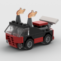
C-Model for Creator set 31085 (Mobile Stunt Show). An oversized hot rod for stunt shows, spewing fire, going fast and loud and getting some nice air time after jumping from ramps. Features: - individual suspension for each wheel (hard front and softer rear for crazy landings) - minifig-scale cockpit with steering wheel, gear shifter and mock gauge - small but openable and functional trunk (set's wrench would fit, or maybe two pizzas?) Pictured is the render of exact .io model of the physical build (aside from the rubber band for the rear suspension) - I don't have enough space and proper lighting to make some good photos.
-
 Designed model is based on the Ford Bronco revealed in 2020. During creation of this model, modular build concept is used to simplify the building process by splitting the overall process on three stages. Follow me on Instagram @anton.kablash Instruction you can download here: Ford Bronco InstructionDimensions: 16 x 38 x 19 studWeight: 738 gFunctions: HoG (detachable) Working steering wheel in the cab Front independent suspension Rear 3 link suspension Working engine Openable doors, hood, trunk Detailed exterior and interior Adjustable seats Modular building More photos in the Ford Bronco Album
 -
 The most special part of this vehicle is the front axle. It has got a tilting mechanism so the car can drive through the turns without falling on a side. The tilting and steering is powered by a single servo motor. The rear wheel is powered by a L motor. The gear ratio can be easily changed. I found the ratio 5:3 as a best option. More photos and building instructions can be found on my website https://tomastechnic.com/.
 -
 Hey everyone, I signed up to Eurobricks because I need some help: I am building a 1:8 scale car right now, and I would really like to make an adjustable suspension for it. Point is: all my prototypes gave up under some weight, or weren't even capable of holding the spring in place... Can someone please help me? I do have an idea: the hole thing could be held by a worm gear.
 -
Dimensions: 29.5 x 49 x 30 studsWeight: 1524 g Instruction: download here To see all my ongoing projects follow me on instagram @anton.kablash Functions: 0. In the model i kept original chassis with improvements and adjustments HoG 4-speed sequential gearbox All wheel drive with 3 differentials Independent suspension on both axles Working detailed in-line 6-cylinder engine Working steering wheel in the cab Openable doors, hood The driver's cab can be tilted for access to a detailed V6 engine Working doors locks Detailed exterior and interior
-
 Just an idea I've had for one of my projects but eventually decided not to use it because it looked wrong for this particular project. It works fine, though, so I'm sharing. It's pretty simple and may be obvious, but perhaps it will help someone.
 -
Check this modern tank. It is not a model of some real tank but I think it don't looks bad. One of the most difficult challenges were to build the suspension strong enough and to make the turret with gun elevating system only three studs height. Propulsion: 2X PF XL motor, turret rotation: PF M motor, gun elevation: PF M motor
-
It was a big challange to build adjustable suspension for this tank/destroyer. My first idea was to use only one PF M motor for suspension tilting but it was not posibble (for me ) to make needed gear reductions in such a small place. So I used two PF M motors (one for first four wheels, one for second four wheels). Only one gear reduction for each motor was needed in this case. This solution brings nice advantages - you can also adjust tank height. For suspension I used torsion bars. It is the easiest way to make it. For more details look at the video. (time: 1:10) If you like this MOC you can look on outdoor video.
-
 I am working on a trophy truck. I am having problems with the rear live-axles articulation. It only turns about 20 degrees. Is this because the links are located far away from the ball joint or is it something else?
-
Tiger 4 x 4 x 4
Zerobricks posted a topic in LEGO Technic, Mindstorms, Model Team and Scale Modeling
After completion and playing with the Leopard for a few months, I noticed the model had a few shortcomings which I wanted to eliminate with this version. These include: Suspension oscilations at high torque High center of gravity Instability on rough terrain at high speeds Most of these issues were due to the usage of the torque tube suspension which is simply too heavy and unresponsive at high speeds. What I needed was to replace the live axle suspension with independent suspension while keeping the articulation needed for offroading. Here's what I came up with: Let's break down the suspension to it's basic components to better understand how it works: Colored green are the main shock absorbers. These caryy most of the wight and provide a high suspension travel Colored orange are the gearbox transfer arms which fix each perpendicular gearbox firmly to the suspension, thereby reducing friction and fixing the U joints to keep them from popping out. Colored black are the side beams which help guide the transfer arms and hold the suspension together Colored in red and gray are the two independent drivelines powering the wheels. Finally in transparent, the suspension arms are made as long as possible for maximum suspension travel. I built the first version with this setup, but soon discovred a flaw. The torque from the drivelines would push the suspension arms down, causing the suspension to stop responding (indicated with red and grey arrows in photo above). In order to solve this problem I added the suspension bridge above, colored in pruple. The suspension bridge performs the following functions: Compensation of the driveline torque Supports 20% of the model's weight Improves articulation when going over rough terrain With the suspension solved, I turned my attention to the chassis. I wanted a model with high torque and high speed. To achieve that I installed a two speed gearbox for each independent driveline powered by a total of 4 RC motors: Finally a very sturdy chassis based on frames was built to support the model. Each axle was given it's own independent steering with servo motor and each driveline has an M motor for switching gears. This redundacy means that even if half of the model breaks down, it can still drive back home. Next step was building the model in real life. Thanks to ForwART's custom stickers the exterrior really came to life: The doors can be opened, revelaing two seats and the steering wheel: Each wheel has over 6 cm of wheel travel, allowing the Tiger extreme articulation rivaling live axle setups: And let's not forget the most important photo of them all: Finally, since there is only so much I can tell in words, enjoy the video experience: As usual the LDD file of the model is available by clicking the photo or link below: https://www.bricksafe.com/files/Zblj/tiger-4x4x4/Tiger 4x4x4.lxf To summarize, compared to the previous Leopard, the Tiger has the following improvements: Improved stability due to the independent suspension and low chassis Higher top speed due to the gearboxes Eliminated suspension oscilation Improved performance at high speed thanks to lighter and more responsive independent suspension Improved maneuverability thanks to all wheel steering Sadly there are also a few drawbacks which I plan to fix in the future version: When pushing the model hard in Ludicrous mode and in low gear the 12 tooth bewel gears can get damaged and need to be replaced Low steering angle (18 degrees) Because only one servo motor is used per axle, steering is more prone to be bumped out of center. -
I started this project because I wanted to share my experiences building various offroad models over the last decade. This topic is meant to guide the builders with comparisments, suggestion and best building practices, It is however not a place to find already finished and perfected designs - that's up to you. Various aspects of the design of the vehicles will be split into several subgroups and explained in details. 1. Number of wheels First thing we need to know is how many wheels our design will have. Most common setups are as following: 4x4 Setup Advantages: 1. The simplest and most widely setup 2. Having only 4 wheels means lower weight and higher performance 3. Higher manoeuverability 4. Simple suspension and driveline design Disadvantages: 1. With only 4 wheels the suspension has to be designed to be as flexible as possible to get the most out of the wheels 2. In a case of a mechanical failure of a single wheel, the whole model's performance is greatly affected 6x6 Setup with double rear axles Advantages: 1. Two rear axle provide more traction area, especially when going uphill 2. Usually 6x6 vehicles are longer than 4x4 and therefore less likely to tip over 3. Since the front and second axle are usually closer than in 4x4 setup, there is less ground clearance needed between them 4. Greater redundancy in a case of a mechanical failure Disadvantages: 1. Lower manoeuverability due to a longer wheelbase even with rear wheel steering 2. More complex driveline and suspension design is required 8x8 or more wheels setup Advantages: 1. Having 8 or more allows for much greater traction area 2. Ability to drive over ditches 3. Because wheels are usually much closer there is much less chances of getting stuck on top of an obstacle 4. Excellent redundancy in a case of a mechanical failure 5. Better weight distribution 6. Less suspension travel required per each wheel as with 4x4 or 6x6 and hence better stability Disadvantages: 1. Lower manoeuverability even with rear wheel steering 2. Powering 8 or more requires a very complex driveline 3. Depending on a driveline, combined torque required for powering all 8 wheels can destroy gears if a single wheel gets stuck 2. Type of wheels and tyres Now that we decided on how many wheels we want for our offroad beast, we have to look into what type of tyres and wheels we want to use. I will hereby cover only the bigger types of tyres and wheels. 1. 94.8x44R Advantages: 1. Low weight 2. Good thread design 3. Low rolling resistance Disadvantages: 1. Low traction, these tyres are prone to slip on the rim at high loads 2. Due to its rounded shape the tyres tend to slide off obstacles when crawling over them 2. 94.3x38R Advantages: 1. Low weight 2. Medium traction 3. Low rolling resistance 4. Realistic design and proportions Disadvantages: 1. Shallow thread pattern 2. These tyres are very hard and don't adjust to the terrain 3. 107x44R Advantages: 1. Low weight 2. Medium traction 3. Very deep thread 4. Currently largest tyres by diameter Disadvantages: 1. High rolling restistance and vibrations due to the thread pattern 2. These tyres are a bit hard and don't adjust to the terrain 4. Power Puller tyres Advantages: 1. High traction 2. Good thread 3. Largest Lego tyres ever produced 4. Deep wheel offset Disadvantages: 1. High weight 2. Hard to use, they require complex hub assemblies 3. Very rare and expensive 5. Outdoor challenger wheels Advantages: 1. Very high traction 2. Very good thread pattern 3. Deep wheel offset 4. Over 7 studs of space inside the wheel Disadvantages: 1. High weight 2. Hard to attach to the standard axles 3. They require a lot of torque to use them at their full potential. 6. Tumbler wheels Advantages: 1. Low weight 2. High traction 3. Very flexible Disadvantages: 1. Low thread pattern 2. Small size 3. Expensive For the 94.8x44R. 94.3x38R and 107x44R tyres we have a choice of two wheels: 1. Racing wheel large Advantages: 1. Good mounting option with axlehole and pinhole 2. Available in multiple colours 3. Cheap Disadvantages: 1. No inside wheel offset means steering pivot point can't be placed inside the wheel. 1. Futuristic wheel Advantages: 1. Deep wheel offset allows us to place steering pivot point inside or closer to the wheel than racing wheel large 2. Slightly larger wheel size stops the 94.8x44R tyre from slipping on the rim Disadvantages: 1. Limited mounting options, with only one axlehole 2. Hard to find 3. Hubs Now that we have our wheels and tyres we need a way to mount and power them. Here are the most common currently available options: 1. New standard ungeared CV hubs These hubs are usually driven by the CV joint counterpart which pops inside Advantages: 1. Low steering pivot offset - usually at the edge of the tyre: 2. Firm wheel mounting 3. Readily available, easy to use and to build on. Disadvantages: 1. Low operating angle - the CV joint can operate to a maximum of about 30 degrees, which limits steering angle. 2. Very low torque transfer - the CV joints are prone to deforming and popping out even with low torque applies to them 3. Low ground clearance 2. Old ungeared CV hubs Advantages: 1. Low steering pivot offset - usually at the edge of the tyre 2. Firm wheel mounting 3. Better ground clearance than newer hubs Disadvantages: 1. Very low operating angle - the CV joint can operate to a maximum of about 25 degrees, which limits steering angle. 2. Very low torque transfer - the CV joints are prone to deforming and popping out even with low torque applies to them 3. Hard to find and expensive 4. No other mounting points than 4 ball joints 3. Built cardan ungeared hubs Example of a hub using a cardan joint to directly transfer the power to the wheel Advantages: 1. Low steering pivot offset - usually at the edge of the tyre 2. Easy to build 3. Can transfer higher torque than a CV joint 4. Higher steering angle Disadvantages: 1. Mounting relies only on the axle and is not as firm as standard hubs 2. Not capable of transferring high torque to the wheels 3. Low ground clearance 4. Standard portal hubs Advantages: 1. Easy to use and to build on. 2. Can transfer very high torque to the wheels when using 8z and 24Z gear combination 3. High steering angle 4. High ground clearance 5. Firm wheel mounting Disadvantages: 1. Very high steering pivot offset - requires stronger steering mechanisms and more fender space for wheel to swing 5. Built portal hubs Advantages: 1. Easy to build. 2. Can transfer very high torque to the wheels when using 8z and 24Z gear combination 3. High steering angle 4. Higher ground clearance than standard portal hubs 5. Low steering pivot offset when using futuristic wheels Disadvantages: 1. Wheels are mounted and held only by one axle, not as firm as standard hubs 2. Hub relies on friction of the components to keep it together, which can slide apart after prolonged use 6. Built planetary hub Advantages: 1. Highest gear ratio of all other hubs, 1:4 2. Firm wheel mounting when using futuristic of power puller wheels 3. High steering angle 4. Lower steering offset than standard portal hubs Disadvantages: 1. Requires old turntable, futuristic or power puller wheels for best results - all are hard to find 2. High number of moving gears 3. Least efficient due to the high friction caused by the large surface contact area and number of moving gears 4. Suspension Suspension is the mechanism that will keep our model's wheels in contact to the ground and will be supporting most of its weight. Most of the designs cover 4x4's Following factors determine the type of suspension system we will use: 1. Weight of the model - The heavier the model, the stronger the suspension components have to be 2. Speed - Faster models require more responsive suspension systems with low unsprung weight 3. Flexibility - The higher the obstacles you want to climb over the more flex and/or wheel travel suspension has to provide 1. No suspension I have yet to see and offroad vehicle without any type of suspension (except for maybe 42070, 42081 and 42082), but I will list my opinion regardless: Advantages: 1. Simple design - having no suspension simplifies our design...and that's about it Disadvantages: 1. No flex over terrain means, there are only 3 wheels at once touching the ground 2. Low stability 3. Poor weight distribution 4. No shock absorption at high speeds 2. Pendular suspension This is the simplest suspension you can put on your vehicle. It basically means one or more of your axles are free to swing about. When using this suspension I suggest using the small turntable where drive axle enters the axle. This will keep the drive axle from carrying the weight of the model, which causes unnecessary friction. 42030 is a typical example of this suspension system. Advantages: 1. Simple, robust design 2. Using this suspension on both axles can give the model very high flexibility 3. If there are no springs used, the model can have perfect weight distribution on left and right wheel Disadvantages: 1. Large unsprung weight, poor responsivness at high speeds 2. No shock absorption means this suspension is not suitable for high speeds 2. When using on one axle, the stability of the whole model relies on the unsuspended axle. 3. When using pendular suspension on both axles springs or a transfer mechanism are required to keep the model upright 3. Single torque tube suspension This suspension became available with the release of the 8110 Unimog. Best examples of this suspension are 8110, 9398 and 41999. It is the simplest suspension which also allows for vertical suspension movement. Advantages: 1. Simple, robust design 2. Universal joints can be placed inside the ball joint, allowing power to be transferred to the axle 3. Easy to implement Disadvantages: 1. Large unsprung weight, poor responsivness at high speeds 2. Axle requires a some kind of a linkage system to keep it cenetred (panhard or parallel links as seen above). 3. Using this suspension on the front axle usually results in negative caster angle which causes higher rolling resistance 4. When used on rear drive axle, the suspension has the tendency to cause oscillate, especially with soft suspension and high power 4. Hard to connect springs to the chassis 4. Double torque tube suspension This is an evolution of the single torque tube suspension, which uses two ball joints to drive each wheel side respectively. It is my own original idea. Advantages: 1. Simple, robust design 2. Universal joints can be placed inside the ball joint, allowing power to be transferred to the axle 3. Easy to implement 4. Self-cenetring, since axles are connected in the center there is no need for linkages to center it 5. Can carry power to each wheel side independently 6. Drive torque compensation Disadvantages: 1. Large unsprung weight, poor responsivness at high speeds 2. Using this suspension on the front axle usually results in negative caster angle which causes higher rolling resistance 3. When used on rear drive axle, the suspension has the tendency to cause oscillate, especially with soft suspension and high power 4. Hard to connect springs to the chassis 5. Parallel floating axle This suspension uses linkages which keep the axle parallel to the chassis of the model. For best functionality and reliability the lengths of all links and that of the double cardan joint should be equal. Also all the linkages and drive axles should be parallel. Advantages: 1. Keeping the axle parallel to the chassis reduces the oscillations effect 2. Better responsivness compared to the torque tubes 3. Neutral caster angle when used on front axles. 4. Self cenetring when using A arm as upper link or 4 link setup 5. Can be configured to carry power to each wheel side independently 6. If configured to carry power to each wheel side independently the drive torque can be compensated. 7. Easy to connect spring to the chassis Disadvantages: 1. High unsprung weight, less responsive at high speeds 2. Increased mechanical complexity, double cardan joints required to carry the power to the axle 6. Half axle independent suspension This is the simplest independent suspension you can build. Best example of such suspension are Tatra and Pinzgauer trucks. Advantages: 1. Independent suspension with low unspring weight, suitable for high speed 2. Robust design with low number of moving parts 3. Easy to connect spring to the chassis Disadvantages: 1. Changes of the caster angle as the wheels travel up and down 2. Hard to implement a drive system that does not carry the weight of the vehicle 3. Hard to implement steering system 4. Wheels tend to drag sideways on the ground when suspension travels up and down, reducing efficiency 7. Trailing arm parallel independent suspension Personally I have not used this suspension yet, but I did use a normal trailing arm suspension which does not keep the hubs parallel. Normal trailing arm suspension which does not keep the hubs parallel acts similarly to torque tube suspension. For the prallel version of the trailing suspension I imagine the following: Advantages: 1. Independent suspension with low unspring weight, suitable for high speed 2. Robust design with low number of moving parts 3. Long links allow for high suspension travel 4. Very easy to connect spring to the chassis 5. Can be configured to carry power to each wheel side independently Disadvantages: 1. Hard to keep the wheels from sagging under the weight of the model. 2. Difficult to transfer power to the wheels 8. Double wishbone suspension This suspension uses two A-shaped arms to keep the wheel hubs in place. As of late it's my favourite suspension system due to: Advantages: 1. Independent suspension with low unspring weight, suitable for high speed 2. Very customizable design with lots of adjustable characteristics (suspension arm lengths, caster angle, camber angle, steering geometries) 3. When build correctly it is far more robust than live axle suspension 4. Increased ground clearance compared to live axle suspension, especially when used with portal hubs 5. Can be configured to carry power to each wheel side independently 6. Extremely easy mounting of springs 7. Very stable compared to live axles 8. Frame holding the suspension can be part of the chassis, therebye lowering the center of gravity Disadvantages: 1. More moving parts as live axle suspension, increased mechanical complexity 2. Limited wheel travel - Lego wishbones allow a max. of around 25 degrees of suspension angle 9. Multi-link suspension To be updated when I build my first multi-link offroad suspension. I can assume the following characteristics: 1. Independent suspension with low unspuing weight, suitable for high speed 2. Extremely customizable design with lots of adjustable charactersitics (suspension arm lengths, caster angle, camber angle, steering geometries, virtual pivot point) 3. Large steering pivot point compensation 4. Increased ground clearance compared to live axle suspension, especially when used with portal hubs 5. Can be configured to carry power to each wheel side independently 6. Very stable compared to live axles 7. Frame holding the suspension can be part of the chassis, thereby lowering the center of gravity Disadvantages: 1. Very high amount of moving parts, increased mechanical complexity 2. Limited wheel travel - Lego wishbones allow a max. of around 25 degrees of suspension angle 3. Hard to connect springs to the chassis 10. Spring types Listed below are the most common types of springs available: 6.5L Soft shock absorber Advantages: 1. Small, easy to implement Disadvantages: 1. One stud of suspension travel 2. Low spring rate, can't support heavy models 6.5L Hard shock absorber 1. Small, easy to implement 2. High spring rate, can support heavy models Disadvantages: 1. One stud of suspension travel 9L soft shock absorber When using 9L shock absorbers I suggest you do not use the default offset upper attachment point, but use an in-line attachment point instead. This will reduce the friction and allow for better high speed performance Example: Advantages: 1. Two studs of suspension travel 2. More attachment possibilities than 6.5 L shock absorber Disadvantages: 1. Default attachment points create friction 2. Low spring rate, can't support heavy models 9L hard shock absorber Advantages: 1. Two studs of suspension travel 2. More attachment possibilities than 6.5 L shock absorber 3. High spring rate, can support heavy models Disadvantages: 1. Default attachment points create friction 2. Rare and expensive 11. Attaching springs to live axles If we start with basics, the first things we have to check is how position of springs affects suspension of live axles. The closer you place the springs together, the more flex the suspension will have, but it will also be less stable: I suggest you to keep springs at a distance of around 1/2 of the total model width. When placing springs you should keep them in-line with the wheel bearing in order to reduce friction. First example of bad spring placements: And example of good spring placement: When using multiple springs make sure to place them symmetrically centrred to the wheel hub: When attaching springs to torque tube suspension, you have to allow springs to tilt in two planes: You can also attach the springs to the suspension links to increase suspension travel. This technique is especially common on Trophy Trucks: 12. Attaching springs to independent suspension Independent suspension allows for much more flexible spring placement. Generally the closer you attach the spring to the main suspension arm pivot, the higher spring travel you get, but lower suspension force. Examples going from the hardest suspension with low travel to the softest with high travel: You can also attach springs inside the suspension arms: Or horizontally: As with the live axles make sure springs are in the center of the wishbones. Example of good placements: And an example of bad spring placement, which causes excessive friction and suspension binding: 5. Steering Steering is the system which allows our model to change direction. Generally there are two types of steering system used: 1. Skid steering Advantages: 1. Very simple to implement and control with two separate motors for left and right sided wheels. 2. Does not require a dedicated steering motor Disadvantages: 1. Not efficient, since wheels have to skid to steer 2. Power had to be reduced or even reversed in order to steer. 3. Not very accurate 4. Not very effective offroad 2. Classical steering with steerable wheels Advantages: 1. Efficient, with minimum loss of speed 2. Accurate 3. Does not reduce the power of the drive motors 4. Can be used in front, rear or all axles for tight steering radius or crab steering 5. Effective offroad Disadvantages: 1. Requires more complex hub assemblies 2. For best steering accuracy you need a dedicated servo motor. Examples of a simple classical steering system for live axles 1. Parallel steering system for live axles Here both hubs are always parallel. Position of the steering in the front or rear rack has no affect on the steering. Advantages: 1. Very simple and robust 2. Easy to build Disadvantages: 1. No Ackermann steering geometry 2. Steering rack moves inwards as it steers, requiring more space. 2. Ackermann steering system for live axles This system allows the hubs to steer at different rates. The steering arms are offset inside so they form a virtual steering point where at the point where lines meet. Advantages: 1. Better steering performance Disadvantages: 1. More complex assembly 2. Steering rack moves inwards as it steers, requiring more space. 3. Steering system with diagonal linkages This system acts similar as Ackermann steering system by using diagonal steering links. Advantages: 1. Better steering performance 2. Steering rack only has to move in one direction without sideways movements 3. Can be configured to be used in front or the rear of the axle. Disadvantages: 1. More complex assembly 4. Simple steering system for independent suspension 1. Very simple and robust 2. Easy to build 3. Can be even more robust when using double steering racks and links 4. Steering rack only has to move in one direction without sideways movements Disadvantages: 1. No Ackermann steering geometry 5. Ackermann steering system for independent suspension Advantages: 1. Better steering performance 2. Steering rack only has to move in one direction without sideways movements Disadvantages: 1. More complex assembly, less robust. 3. General steering tips 1. When using independent suspension always make sure your links are paralel to the suspension arms, otherwise you may end up with wheels which are not parallel and are causing excessive friction: 2. When using standard portal hubs make sure your steering system is robust enough to deal with the forces generated by wheel driving into obstacles. 3. If possible use servo motors which allow for high steering precision and return to center. They are especially useful at high speed models. 4. Most efficient way to steer the wheels is using the steering racks. 5. Build axles in such way they have positive caster angle, example for direction of travel from right to left. This will self-center your wheels and reduce rolling resistance. 6. Drivelines Drivelines are the responsible for transferring the power from the motors to the wheels. There are various drivelines you can build, here I listed few with their characteristics: Driveline types 1. Permanent 4x4 Advantages: 1. Simple, centralized, low mechanical complexity 2. Wheels are always powered, great offroad performance 3. Light weight Disadvantages: 1. Poor steering radius 2. Tyres have to skid when steering, lowering efficiency of the model 2. 4x4 with open differentials Typical example of this driveline is 42070 Advantages: 1. Differentials allow the wheels to so spin at different rates when steering 2. Very efficient since wheels don't have to skid when steering Disadvantages: 1. If one wheel loses traction, all the power is transfereed to it, poor offroad performance 3. 4x4 with lockable differentials Advantages: 1. Differentials allow the wheels to so spin at different rates when steering 2. Very efficient since wheels don't have to skid when steering 3. All differentials can be locked, so wheels are powered for great offroad performance Disadvantages: 1. Higher mechanical complexity 2. Dedicated motor is required to actuate differential locks, higher weight 4. Axle mounted motors Typical example of this driveline are 9398 and 41999. Advantages: 1. Differentials allow the wheels to so spin at different rates when steering 2. Very efficient since wheels don't have to skid when steering 3. If one wheel gets off the ground the second axle can still pull/push the model. Disadvantages: 1. Higher mechanical complexity 2. Usually the rear axle motor is more loaded than the front, especially when climbing uphill, the motors can't "help" each other. 3. Worse offroad performance than permanent 4x4 5. H drive: This is my favourite driveline due to the following reasons: Advantages: 1. Motors allow the wheels to so spin at different rates when steering 2. Model can skid steer 3. Very efficient since wheels don't have to skid when steering normally 4. Having 2 drivelines allows you to carry more torque to the wheels 5. Redundancy, even if one drive fails the model can still move 6. Wheels are always powered, great offroad performance Disadvantages: 1. Higher mechanical complexity 2. Slightly higher weight 6. Wheel motor drive Each motor powers a wheel independently. Advantages: 1. Motors allow the wheels to so spin at different rates when steering 2. Model can skid steer 3. Very efficient since wheels don't have to skid when steering normally 4. Redundancy, even if one or more motors fails the model can still move 6. Lower mechanical complexity Disadvantages: 1. Motors can't "help" each other 2. Higher weight due to a higher motor count Transferring power axially When transferring power via axles, you can reduce the flex by using connectors instead of simple "bare" axle: Use axles with stops to prevent them from sliding out of gears: Where possible always brace tooth gears from both sides: Transferring power at an angle Where pairs of U joints are used, make sure to align them to eliminate vibrations: Brick built CV joint which can transfer high torque at over 30 degrees angle Brick built cardan joint which can transfer extremely high torque up to 15 degrees angle Brick built flexible drive which can transfer medium high torque, extract and retract, suitable for low angles Transferring power perpendicularly The following perpendicular gearboxes are the best suitable for transferring high torque Avoid knob and worm gears, because they waste energy Gearboxes In my models I generally use the following gearboxes: 1:3 differential gearbox Advantages: 1. Very high gear ratio between low and high gear, 1:3 2. Capable of transferring high torque 3. Very efficient since only 2 gears are used at any time Disadvantages: 1. Takes a lot of space 2. This gearbox requires a good housing to brace the gears properly Compact two speed gearbox Advantages: 1. High gear ratio between low and high gear, 1:2,77 2. Capable of transferring high torque 3. Very efficient since only 2 gears are used at any time 4. Very compact design Disadvantages: 1. Requires two of the rare 20 tooth clutch gears 2. More complex shifter assembly. Diagonal gearbox Advantages: 1. High number of gears 2. High gear ratio possible, over 4:1 2. Capable of transferring high torque 3. Very efficient since only 2 gears are used at any time Disadvantages: 1. Takes a lot of space 2. Input and output axles are not parallel. 3. A complex shifting assembly is required for sequential operation. Driveline effect on suspension Transferring torque on the wheels can affect the suspension, especially when live axles are used. The following photo shows how the torque causes one side of the axle to push down and the other to lift up: In order to minimize this effect I suggest the following: 1. Make sure to have most if not all the downgearing inside the axles, so you do not need high torque going to the axles. 2. Make sure your models have a low center of gravity 3. You can eliminate this effect by using two counte rotating axles which cancel each other's torque, example below: 7. Motors and control Following are the most common types of motors used for Lego models. You can find more info here: http://www.philohome.com/motors/motorcomp.htm My personal favourites are L and RC motors due to the balanced output speed to torque ration and great mounting options. 1. PF-M Advantages: 1. High speed output 2. Smallest available motor 3. Cheap and available Disadvantages: 1. Low torque 2. Poor mounting options 2. PF-L Advantages: 1. High speed output 2. High torque 3. Cheap and available 4. Great mounting options Disadvantages: 1. Odd shape 3. PF-XL Advantages: 1. Very high torque 3. Cheap and available 4. Good mounting options Disadvantages: 1. Slow speed output 2. Large form factor 4. PF-Servo Advantages: 1. Very high torque 2. Very precise output with 15 positions 3. Good mounting options Disadvantages: 1. Slow speed output 2. Output axle can move a max of 180 degrees 3. Large form factor 4. Hard to find 5. 9V-RC motor Advantages: 1. Most oowerful Lego motor 2. Very high speed output 3. Good mounting options 4. Two output axles with different gearing ratios 5. Drive axles can pass through the motor Disadvantages: 1. Low output torque 2. Low efficiency 3. Power hungry 4. Odd form factor 5. Hard to find and expensive Power options 1. PF - AA battery box Advantages: 1. High capacity 2. Good mounting options 3. Works with rechargeable batteries, but with lower performance 4. Cheap and easy to find Disadvantages: 1. 750mA current limit - not enough to fully power RC motor 2. Heavy 3. Has to be removed and opened to replace batteries 4. Wasteful 5. Odd form factor 2. PF - LiPo battery box Advantages: 1. Small form factor 2. Light weight 3. Easy to recharge Disadvantages: 1. 750mA current limit - not enough to fully power RC motor 2. Low capacity 3. Studded design 4. Expensive and hard to find 3. RC control unit Advantages: 1. No current limit - can power 2RC motors at once 2. 3 Power levels 3. Has integrated steering output with 7 positions 4. Good mounting options 5. Easy battery replacement 6. Radio based control Disadvantages: 1. Poor quality, prone to breaking 2. Limited angle (45 degrees) and torque from the steering output 3. Has to be removed and opened to replace batteries 4. Very large form factor 5. Expensive and hard to find 6. Heavy 7. Required dedicated antennas and remote Control options 1. PF receiver and controller Advantages: 1. Receiver is easy to integrate into the model 2. Controllers have physical feedback 3. Cheap and easy to find Disadvantages: 1. IR based, low range, useless outside 2. Lack of PWM motor control, unless using train controller which is awkward to use 3. Odd form factor for use with steering 2. RC control unit See above 3. Third party options such as BuWizz and Sbrick Advantages: 1. Smaller form factors, easy to integrate into model 2. More outputs than PF system 3. Smooth control of motors 4. High range thanks to Bluetooth control 5. Higher power available with BuWizz 6. Customizable profiles Disadvantages: 1. Smart device is required 2. No physical feedback 3. Sbrick is limited by PF battery box 4. Price 8. Chassis Chasis is the backbone of your model which olds everything together. For chassis I suggest you to use the following components in order to make it strong and robust enough to deal with the stresses involved when crawling or driving at high speed: Some flex in the chassis might be a good thing to improve offroad capability, but only if id does not affect the driveline and cause friction on the drive axles. Remeember to use diagonal support, since triangles are the strongest shapes. You can also use panels and motors as structural support. Interlocking your chassis will keep it from slipping apart. For good examples of chassis designs I suggest you check the instructions for 9398 and 42083.
-
Yes, there are dozens upon dozens of LEGO models of the Sherp ATV. I’ve only decided to build my own because I had this idea about how a suspension could be added to it (yes, the real Sherp has suspension according to the manufacturer) and I just had to try it out. The result is a dead simple vehicle that can go 7 KPH on flat terrain and literally rips through snow: Photos & reading: http://sariel.pl/2019/01/sherp-atv/
-
This model is a result of the lessons I learned while building a mini racer and failing. You can find more details about that here: To create a better mini racer, I increased the scale from 1:16 to 1:12 which allowed me to implement the following functions and features: Independent left/right side All Wheel drive Independent suspension on all wheels Dual 2-speed gearbox Steeering angle of around 30 degrees Working steering wheel Full interior with 2 seats Opening doors and bonnet Built out of 999 pieces Measures 35 x 16 x 10 cm Weight of 1 kg For color, I had the choice between orange and lime, so I went with lime for that Lamborghini look with gold rims: And here's the LDD version in all of it's 999 parts: Here are more photos of the individual groups, starting with main driveline: Gearbox switching system actuated by a PU L motor: Steering and rear hub support system: And finally the suspension system which also provides support for the bevel gears: The driveline is the most important part of the model and it uses two 2-speed gearboxes, each driven by both outputs of the BuWizz motors. A PU M motor switches the gears using the wave selectors. Suspension is supported by 8 hard shock absorbers. The suspension is at quite a high angle of around 25 degrees in order to keep the drive motors, steering motor and BuWizz as low as possible. High suspension angle also pulls the wheels together, allowing for a narrower bodywork. A PU L motor provides some 30 degrees of steering angle to the front wheels and also steers the steering wheel via a secondary steering rack. Everything is powered and controlled by a BuWizz 3.0 hidden in the front. Here's how everything looks like inside the model: More details and video of the model in action can be found in the video: To finish, I'm really happy both with performance and the looks of the model. It for sure fixed and improved mostm if not all the issues with the previous, smaller version. I also can't wait to compete with when the next opportunity shows up.
-
This is a small AWD Trophy truck that I was able to build thanks to the new components in the Skyline, specifically the 4L links and the 4L CVs: The biggest challenge with this model was in finding a solution for the FWD which would allow for high suspension travel and a good steering angle while being limited to 25 degrees of movement of the CV joints. I decided to bring the front suspension arms closer together, therebye creating the following suspension geometry which forces the front wheels to move in an arc: This in turn has several advantages: Reduces the angle the CV joint has to carry the power on the outboard side Allows for a higher steering angle Increaces the ground clearance on the bottom As such the front suspension is supported by 2 soft shock absorbers. Notice how the L liftarms hold the suspension together, supported by a white bar that goes through the cross hole: The rear suspension uses the normal equal length parallel arm design and it's supported by a combination of a hard and soft shock absorber which are placed at an angle to simulate a progressive setup: The front axle also uses double steering rack simillar to 42160 with 4 steering links to keep the front steering system as accurate, robust and stiff as possible (Please note, there are no 4L link yet available in LDD): Originally the driveline used a 12:20 gearing from the motor to the main shaft and than the 20:28 to the wheels. I used a couple of bevel 20 tooth gears so that a 5x11 panel could fit under them to protect the gears. But during video shoot, the solution proved to be a weak point, so I redesigned the driveline to use a pair of 16 tooth gears and a 12:28 diff combo which gives me the same gear ratio, yet with added strength: The only weakpoint left were the small CV recepticles: But after reducing the current limtiters from 2 to 1.5 A, I have yet to suffer a failure, even when suddenly changing directions. You can see the model in action here: I have to say this is a really compact, fun and almost indestructible model and I'm really happy how it turned out. Now if only LEGO could come up with a 4L version of the large CV joints...
-
While brinstorming ideas, I came up with a really wacky idea. Why not build a classic, but give it a twist? With that in mind, I decided to build a 1:12 scale DeLorean with tracks for wheels and the following functions and features: Motorized drive and steering using PF L and 1 PU L motor Powered and controlled by a BuWizz 3.0 AWD Independent suspension on all.. Tracks? Tiltable track bases Working steering wheel Working V6 fake engine Openable gullwing doors Fully detailed interior with 2 seats Accurate shaping using a 3D reference This is the result and the current WIP status: As with all my replicas of real models, I found a 3D reference model, edited out one of the doors so that interior is better visible and imported it into LDD: As you can see, the model follows the reference quite well given it's scale, I even went into the detail of slightly tapering both bumpers. Of course the wheel arches and before mentioned bumpers had to be slightly cut to fit the tracks, but the model should still be instantly recognizable. So now it's just the matter of building it from real bricks, I will post WIP photos as the project progresses.
-
 Hi everyone. I’d like to introduce to you my latest MOC: Technic RC Pneumatic Dump Truck. It is on 1:17 scale, weighing in at 4.32kg with just over 5,000 parts. It is loosely inspired by the SinoTruk Howo 8 x 4 Tipper Twin Steer. I would love to get your thoughts & feedback! More pictures on Flickr HERE Instructions: BuWizz, 2.4GHz Feature Summary Powered by 2 x BuWizz 2.0 or 2.4GHz Box. RC Drive 8 x 8. RC Twin Steering. Springless Live Axle Suspension Front & Rear with maximum roll stability. RC Compressor. RC Pneumatic Functions. Tip Dump Bed & Driver Cab independently. Dump Bed Automatic Gate Lock with optional Manual Override. Opening Doors with Spring-Loaded Latch. Foot Pedals (Brake & Accelerator), Signal Levers, Gear Shifter, Air Horn Chain, Ignition Key, opening Glove Compartment. Working In-Line 6 Cylinder Engine (Connected to Drive Shaft) Working Steering Wheel full-time, even when Cab is tipped. Opening Hood, revealing Engine Fan. Adjustable Sun Visors, Mirrors, Windshield Wipers. Technic Figure Compatibility. Locking Feature to secure Dump Bed & Driver Cab to Frame to add rigidity & facilitate ease of model transport. Video Comparison Pictures Locomotion All motorized functions are powered by dual BuWizz 2.0 or 2.4GHz Units integrated into the Cab. The model features RC Drive, with a full 8 x 8 train. Propulsion is delivered by 4 x PF XL Motors, geared down at 2 to 1 with the help of Planetary Hubs. There are no Center Differentials, which ensures that all 4 axles are driven full-time. The drive train is also connected to a (cosmetic) inline 6-cylinder Engine, complete with a fan. With an empty Bed, the weight distribution is closer to the front, which limits the traction on the rear wheels. In practice, the 8 x 8 drive configuration results in much better outdoor & overall performance (particularly over uneven terrain). Individual axle-mounted PF Servo Motors steer the Truck through a Rack & Pinion system, & this is independent of Suspension flex. Axle 1 (forward) has a tighter turning radius than Axle 2. There is a mechanical linkage connecting the system to the Steering Wheel in the Driver Cab with a +/- 167 deg range for a more realistic look. This function remains operational even when the Cab is tipped. Suspension All 4 Axles feature Live Suspension. Both the front & rear wheel sets are connected in tandem, similar to a Walking Beam configuration. By combining traverse & longitudinal pendular levers, articulation is achieved without the use of shock absorbers. This also offers maximum roll stability for high center-of-gravity applications. This idea was inspired by the All Terrain Crane by @Jennifer Clark. Pneumatic System The Pneumatic Circuit uses compressed air to control the pistons that operate the Bed & Driver Cab tipping functions. A Compressor generates pressurized air that is then redirected towards the pistons through corresponding switches. At the heart of the Pneumatic system is the Air Compressor. It is driven by a PF L Motor using 2 Pumps aligned out of phase for smooth flow. Compressed Air is fed to the Pneumatic Switches that control the tipping functions. The model features 2 Pneumatic functions: Tip Driver Cab & Tip Dump Bed. The air supply from the Compressor is redirected through Pneumatic Switches, which in turn control the Pneumatic Pistons that operate the functions. The Switches are activated by PF Servo Motors. With the Compressor turned on to supply airflow, the Servo angle (-90, 0, 90) corresponds to the Switch positions (-1, 0, 1), which then moves the Pneumatic Pistons as (retract, neutral, extend). Full credit to @functionalTechnic for the original RC Pneumatic Servo set-up. The Dump Bed tips at up to 45 deg & has a lifting capacity of 2.5 kg, with a total volume of 3,623 cubic cm. Gate Lock The Dump Bed contains a gravity-based Lever that automatically releases the Gate as soon as tipping begins. Conversely, it is timed to lock the Gate once the Bed is horizontal. An optional pin is included that secures the Lever in position so that it doesn’t release the Gate upon tipping. Driver Cab Details The Driver Cab features functional doors with a spring-loaded mechanical linkage to open & lock them. This mechanism fits in a single stud width & once locked, the door is fully constrained to the Cab. The driver side contains Foot Pedals (Brake & Accelerator), Air Horn, Signals, Ignition Key, Gear Shift Lever. The Windshield Wipers, Mirrors & Sun Visors are all independently adjustable. The Hood on the front opens to reveal a working Engine Fan. Finally, Technic Figure compatibility has been maintained using vintage seats. Admittedly the Technician scale isn’t 100% accurate, but it is never a bad idea to include them. Locking Elements Both the Driver Cab & Dump Bed feature locking mechanisms that reinforce the tipping functions. This is ideal for model transport, where it can be easily lifted from above from any of the sections. Typically, it would be carried from beneath or by holding the front & back. Aftermarket Tires While the standard 62.4 x 20 tires work well, but the RC4WD 1.2” variants have always been preferrable. They are a bit larger & have a more rugged look overall. Due to the weight of the model, the supplied foam inserts were not sufficient for the tires to retain their shape. To overcome this, custom inserts were designed & 3D Printed for the Dirt Grabber option. They consist of symmetrical halves that are joined together on the rim & secured with Technic ½ Pins. The ID features inner shoulders that prevent lateral movement relative to the rim. More Pictures
 -
This is a model I've been working on for a few months for the BuWizz gathering and now it's finally time to showcase it. The rules required a 1:10 scale model built after a real vehicle with a working gearbox, steering wheel and fake engine powered by a maximum of 2 BuWizz motors. I also managed to squeeze additional functions and features as following: 2x BuWizz drive motors 1x BuWizz 3.0 for control Working steering wheel actuated by a PU L motor 2 Speed motorized gearbox controlled by a PU m motor All Wheel Drive using planetary hubs Independent double wishbone suspension on all wheels with around 2 cm travel Working fake V12 coupled directly to the drive motors Detailed interiror with tilting rear seats to access the BuWizz Detailed exterior with opning doors, bonnet and tailgate Built out of around 2850 pieces 47 x 21 x 18 cm Weighs around 3 kg As usual with my representations of the real vehicles, I first started with sourcing, editing and importing a 3D reference into LDD. Here's how the digital model looks compared to the LEGO version: And here's the LEGO version without the reference: I hid the doors, bonnet and the tailgate in order to show the detailed interior: The driveline is very compact and efficient. Two BuWizz drive motors are placed right behind the rear seats and power the 2 speed gearbox and an (oversized) V12 engine directly. As with the real vehcile, suspension system is independent at all 4 corners. Steering system is actuated by the steering rack directly and geared up. Gearbox is activated by a PU M motor via a linear clutch and a wave selector: So that was the theory... After a few small fixes and corrections, this is how the finished model looks like in real life (oops, I lost my license plate): Rear view showing the spare tyre, detailed lights, guardrails and exhausts: Doors, bonnet and the tailgate can open up to reveal the massive V12 engine and front shock absorbers: Interior features an adjustable and working steering wheel, 4 fully detailed seats, console and a transmission tunnel. Rear seats can be tilted individually to access the BuWizz 3.0 for charging; Here's a view of the back with the opened tailgate. Thanks to the central motor placement, there's a lot of free space: One of the design goals was to protect all the gears and drive axles from dirt and to keep the bottom as flat as possible. I think I did very well, it's smooter than the real vehicle in that regard: And finally here's a video where among other details you can see how well it performed at the competiton: If you want to have an even more detailed look, you can download the LDD file here: https://bricksafe.com/files/Zblj/lamborgini-lm002/Lamborghini LM002.lxf To summarize I'm really proud of this model. It looks, performs and just feels good and hits all the right spots. One thing's for sure, I'm keeping this one assembled, as I trully believe it's one of the best models I ever designed.
-
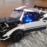 Hi everyone! Today I want to present you an off-road car, that I've been working for quite some time. There were several attempts, some of it ended up as unpolished models, without all features I initially had in my mind, and some were just concepts of gearbox, axles, etc. These were my initial assumptions on the model: Sturdy drivetrain and gearbox with a wide range of gear ratios Remotely lockable both front and rear axles Up to 1:10 scale, nothing bigger Utility vehicle - it must be able to climb step hills and also provide decent speed on plain terrain Removable body (if it would have one) Precise low speed control - to provide maneuverability over a variety of obstacles Planning the wheelbase and car elements, based on an existing vehicle - to ensure the authenticity of the model Using trusted A2212 1000kv BL motor and other RC components to power it Gearbox I always try to start with a gearbox if my model would feature one. The idea was to make it simple, yet robust. In order to achieve it, I needed to make sure each important gear will be supported by another. My other goal was to make a gearbox with a wide range of gear ratios, so at least for example 1:1 - 1st gear and 1:3 - 2nd gear. The Gearbox I use worked well in my previous concept model I didn't present here. Final gear ratios are: 1st gear: 63.787:1 2nd gear: 16.329:1 3.9 times difference between first and second gear! Now you may ask how I achieved this based just on a picture below, but we will get into that later. Axles I went through massive amount of research to have a working concept of both front and rear axle, that is driveable, able to turn (front axle) and also featuring locking mechanism somewhere. None of the concepts on the Internet were actually fitting my model. I do not have small technic pistons (I am looking at you Lego Technic Emirates), and it didn't seem I would have a chance of finding something different that will work in my case (rc car). I also knew I would use geek-servo for locking system, so only 90-degree turn must provide option for locking and unlocking mechanism. Gray 2L driving ring is actually a new one - 2473. It is not yet added to Lego studio, but the existing ring was working for me just fine. With that concept of the axle, I just needed to make sure the upper steering arm is angled, because other way it would collide with the gears. That angle is perfectly calculated, so I could work on finishing the axle, adding steering (for the front) and most importantly - locking differential mechanism. The finished front axle features: 2x 9.5L hard springs, 3x steering arms to cooperate with springs, 4x steering links, lockable differential mechanism. Did I tell you this was my own first solid axle build attempt? I guess it may be called multi-link suspension, but you have to correct me on that one. Locking differential mechanism on axles As you probably already noticed, this whole model is based around locking differentials functionality. When I was organizing my parts, I came upon instruction of my CADA C61006W, which featured locking differentials in similar scale. The idea of having one gear turning around 90 degree and pushing by it two different gear racks at the same time was splendid. That movement could rotate 6641 Changeover patch part, and thus lock and unlock 2L differential, that was the key of my goal. I went to the drawing board and after some time I created this. As you can see, If I would rotate 12T black gear to the left around 90-degree, it would push by using 6641 and 64781 parts the 2L 2473 driving ring. I just needed to make sure pivot points are correct, so the mechanism wouldn't move unnecessarily during suspension work. Chassis It needed to be as symmetrical as possible, due to previously mention features. I simply wanted it to be robust. I do not focus much on exterior or accessories - it just adds unnecessary weight to the model. The chassis also needs to have all points to attach both axles to. Body Let me just start with one sentence, I am not proud of the body. I am also not a great body sculptor. The overall design was based on Ford Bronco Badlands from 2021, but I only planned wheelbase and door placement around it. The rest was improvised, simply because I don't like rebuilding 1:1 real cars in Lego. The body is detachable and features opening doors and hood. Power system and drivetrain Ah yes, we are approaching icing on a cake. The model is, like I already mentioned, powered by A2212 1000kv BL motor. It also features 3x geek-servos: steering, changing gears and locking differentials. On top of that, I developed some sort of RC-hub (mostly because I want to organize everything in one place). This hub contains 3s battery, receiver and esc. It also features Lego Technic dimensions: 9x9x4 studs. If you want to know more about all of that, check out Brushless motors in the lego world - general topic. As you can see in the top right corner, there is an A2212 motor directly hooked to the planetary hub. This way revolutions are downgraded to let's say civilized number (from 11100 RPM to about 2000 RPM - similar to buggy motor in fast output). This also provide us built up torque, which we will for sure need in off-roading. Summary I am really proud of this model. Especially because it taught me many new things in Lego Technic world. I believe some of you can also learn from my problems and how I approached them. Here are some numbers that may interest you: Weight: 1.590 kg Length, width, height: 43x19.4x16.9cm Theoretical max speed 1st gear: 2.67km/h Theoretical max speed 2nd gear: 10.44km/h Soon I will be able to record some footage of all the features of the car and of course playtime! For now, I have more photos and GALLERY for you.