Search the Community
Showing results for tags 'tracked vehicle'.
Found 11 results
-
[MOC] Morooka Tracked Dumper
Arie posted a topic in LEGO Technic, Mindstorms, Model Team and Scale Modeling
I have finally found the time to finish this MOC of a Morooka tracked dumper. It is loosely based on the Morooka MST 2200VD. The model is controlled using an S-brick and powered by the regular lego technic power functions battery box. Each track is driven by an PF L motor with a 1:1 ratio, giving the model plenty of speed and enough torque to drive over obstacles etc. Dumping is also motorized using a PF L motor driving a linear actuator. The battery box is hidden under the openable hood, and can be easily accessed and removed (although a lot easier if the dumpbed is up :)) Other functions include an openable door and a lock for the gate on the dumpbed, that opens if you dump. I tried to make a video but you guys will have to wait a bit longer because my baby is making a lot of noise in the background so I have to make a new one sometime when he is asleep :) Edit: made a new video - the period in the beginning when nothing happens is when the buwizz in the tractor fails to connect Some more pictures: https://bricksafe.com/pages/Arie/tracked-dumper Let me know what you think! -
FT's Technic corner - MAN TGS 6x4 with bucket gripper
functionalTechnic posted a topic in LEGO Technic, Mindstorms, Model Team and Scale Modeling
Hi everyone, Finally, I have finished a project which I was building since last September. It is the scale model of the Intrac 2011 snow blower which is/was often used in the swiss alps by the army and other communal parties. It was the aim to create another working snow blower after the success of the snow blower from last winter. The blower is powered by three buggy-motors which are all controlled by a separate Sbrick. Each track is driven by two PF XL motors. The snow blower shoot direction is controlled by two 9-volt micro motors and the height of the snow blower by one PF L motor. As power source I used two Buwizz as battery or a custom lipo battery. After a certain time in the cold I had the replace the Buwizz with the custom lipo battery. Cheers FT -
[MOC] Lego Technic RC A11 Matilda I Light Infantry Tank
Tarix819 posted a topic in LEGO Technic, Mindstorms, Model Team and Scale Modeling
Hi, I wanted to show my latest model, which is of the A11 Matilda I, a British Infantry Tank that was in production from 1937 until 1939. It saw brief service at the beginning of the Second World War with the British Expeditionary Force during the Battle for France in 1940, probably the most famous battle it participated in was the Battle of Arras, where it was found the Matilda I was almost inpenetrable to most German anti-tank guns, having 60mm of frontal armour protection. After the withdrawal of the British Army from Dunkirk, the Matilda I was seen as obsolete and withdrawn from service. Features: -1:8 Scale. -6.4kg Weight. -Powered by four PF-XL Motors for the tracks. -The Hull is powered by two SBricks and two battery boxes fitted with 14500 Li-Ion batteries, providing 22.2v of power for the hull. -There is an SBrick and 7.4v Li-Po battery box in the turret which powers only the Commander's Periscope. -Nine motors in total, 4x PF-XL, 5x PF-M. -The Engine is a Ford V8 Model 79, accurately represented in the hull. -Functioning headlights. -The turret can be traversed 360 degrees, and the main .303 Vickers Gun can be elevated and depressed. -The Commander's Periscope can be traversed 360 degrees, the Driver's Persicope can be rotated with limited traverse. -Functional track tensioners. -Functional and accurate leaf spring bogie (Horstmann) suspension. More images: -
[MOC] Lego Technic RC Vickers M1937 Light Tank
Tarix819 posted a topic in LEGO Technic, Mindstorms, Model Team and Scale Modeling
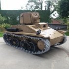
Hello, Here is my latest model, which unfortunately I didn't manage to finish filming before the New Year: The model is of the Vickers M1937 Light Tank, a vehicle designed and produced by British arms manufacturer Vickers-Armstrongs in 1937. This was to be the fourth member of Vickers' line of commercial light tanks, coming after the successes which were the M1933, M1934 and M1936 (the latter which I have already built). The turret was to be enlarged, and a Vickers 40mm Anti-Tank gun fitted, providing the anti-armour firepower that the M1936 lacked. It had a crew of two men (Commander and Driver), and 9mm of armour protection. The vehicle only entered service for a short time in Latvia, before it was quickly outclassed by more modern designs. The only surviving vehicle remains at Kubinka Tank Museum in Russia. I decided to build this Tank because it shared most of the components with the Vickers M1936, and I didn't have much time over Christmas to build, so I thought this would be perfect. I intend to also make building instructions for it, although this takes time, I decided to get the video out and then finish the building instructions afterwards. Features: -1:8 Scale, the vehicle weighs 5.6kg. -High mobility - the vehicle is powered by four PF-XL motors for the tracks. -The hull is powered by two SBricks and two battery boxes fitted with 14500 Li-Ion Batteries - this is unchanged from my previous two models (Vickers M1936 and Vickers Mk. E (B)) and provides a total of 22.2v for the hull. -The turret is powered by one SBrick and one 7.4v Li-Po battery box. -There are nine motors in total; three for the turret and six for the hull. -The firing mechanism is powerful and features a recoil effect that functions even more smoothly than on my Vickers Mk. E (B) and A34 Comet. The spent shell casings are ejected into a collection tray inside the turret, and the magazine can hold up to four shots. This firing mechanism is a smaller, more reliable version of the one I fitted in the Vickers Mk. E (B). -The engine is a Meadows ESTE Six-Cylinder, which I have accurately represented in the hull from the few pictures of this particular engine online. -The headlights and rearlights are functional. -The turret can be traversed 360 degrees and the main gun elevated and depressed a few degrees each way. The turret bustle at the rear is slightly raised as it was in real life, so that it does not hit the driver's compartment at the front of the Tank. -Track tension can be adjusted using the track tensioners, which there is one for each track. This makes it easier to remove the tracks if need be. -The suspension is a type of Horstmann suspension, with there being four bogies each with two roadwheels, fitted with coil-spring shock absorbers. The shocks are the extra-hard type, to support the heavy weight of the vehicle, though I have replaced the yellow part with the equivalent black part of each shock absober for aesthetic purposes. -The two battery boxes can be removed through a hatch in the rear of the vehicle, and can be switched on/off through two hatches to the right of the turret. I didn't demonstrate this in the video, however I did demonstrate largely the same process in my Vickers M1936 video. -The vehicle also has other details, such as a fire extinguisher, exhaust, vision slits, vents and hatches. Pictures: -
[MOC] Lego Technic A34 Comet Cruiser Tank
Tarix819 posted a topic in LEGO Technic, Mindstorms, Model Team and Scale Modeling
If some of the images aren't showing up, here they are linked on Imgur: https://imgur.com/gallery/lLRkXIL Greetings all! Here is the post on my new Lego Technic model, which is of the British Second World War Cruiser Tank, A34 Comet: It entered production in late 1944 but didn't see proper service until early 1945. By Second World War standards it was an excellent vehicle, being fast, well armoured and equipped with a powerful QF 77mm HV gun capable of dealing with almost any enemy tank. It also saw action during the Korean War, however was shortly after superseded by the Centurion Main Battle Tank. The Korean war saw the introduction of the Comet Model B, with the large engine vents sticking out like a spoiler, as shown in the image below. My vehicle is of the Model A which was used during the Second World War, which is noticeably different as it lacks this 'spoiler'. Some information: Weight: 5.9kg (Making it possibly one of the heaviest Lego RC tanks on YouTube). Dimensions (mm): 290 width x 680 length (830 including the length of the main gun) x 300 height. Motors: Nine Power Functions Motors in total (2 XL, 2 L and 5 M) Driving is done by the two XL Motors alone. Fully functioning headlights and turret lamp. Traversing bow machine gun. 360-degree traversing turret. Elevating and depressing main gun. Shooting mechanism which fires projectiles through the barrel. Recoil mechanism for the main gun. Spent shell casing ejection system - dispenses through the floor at the rear of the turret for collection (Not enough room for a proper collecting tray). Powered by one PF 7.4v Li-Po Battery Pack in the turret, and one AAA Battery Box in the hull. The AAA Battery Box is equipped with three 3.7v 10440 Li-Ion Batteries and three AAA dummy batteries which when fully charged give the vehicle 11.1v of power, though they need to be recharged somewhat more often than a usual 6x 1.2/1.5v Battery Box would. This is how such a heavy vehicle can drive so quickly. Another benefit of this power set up is I could take the advantages of programming in the SBrick (Which is how the firing mechanism works), whilst achieving almost the same voltage as the BuWizz, without spending so much money. The firing mechanism is quite powerful, and the footage doesn't really do it justice (probably in part due to the quiet sound), though its power is somewhat reduced by the length of the barrel and the small space inside the turret, still it is a good deal more powerful than most Lego Tank firing mechanisms on YouTube. It alone is controlled by three M motors. Speaking of the firing mechanism, this is the sole reason the model is so big. My firing mechanism as you have read is very functional, however it is also quite large and I needed more space inside the turret for it, as well as the Li-Po, SBrick and Elevation/Depression mechanism, and on top of that, room for it to recoil. The Comet already has quite a large turret in comparison to its hull, if I decide to build tanks with smaller turrets, they would be to an even larger scale. The tank can only turn reliably on smooth surfaces due to its immense weight, however it is at least able to. Powered by two SBricks, one for the turret and one for the hull. A few last images: First photo of the in-development hull, I started work in early December 2019. Photo of the in-development turret, showing the mechanism and SBrick. Early photo of the turret married to the hull. Taken some time over Christmas. The placeholder three-cylinder tractor engine I had in the tank before I built one which looked more like the Rolls-Royce Meteor. I like my 'Expert Builder 1977-1980' style of Technic engines.The SBrick and Li-Po (Which was originally in the hull) can be clearly seen. Photo of myself next to the mid-development vehicle. The thing is huge and a pain to carry around. The vehicle at about 90% completion. The vehicle compared to the 8865 Test Car, showing the huge scale of the model. The almost completed vehicle compared to the size of a mug. Prior to some last suspension changes, though the front fenders have been improved. Thanks for reading. -
[MOC]- Soviet Tracked Vehicle BWSM 80
Samolot posted a topic in LEGO Technic, Mindstorms, Model Team and Scale Modeling
BWSM 80 was a prototype of a "sanitary" vehicle created by combining the DT 75 bulldozer with a GAZ 53 cab. I've found its picture in the RU-net already a few years ago, but it waited for its turn in a folder with inspirations. It used to be orange Porsche that I could build Zila 130 now from blue Bugatti I made Gaz 53. I wonder if a new secular tradition was created? Three weeks of holiday in the countryside was enough to build this 60 cm model. There were several challenges in the construction. Weight, the model could not be too heavy because it had to rise and ride on tracks. It determined the entire construction. I could not use too many PFs, a complicated suspension, fake engine under the hood and details of the interior. The biggest challenge arose, how to use the two PF-L to master the drive in three variants. 1 Only wheels 2 Only caterpillars 3 Wheels and tracks simultaneously For a good balance, the motors and Battery Pack are at the end of the vehicle. In front of the PF L motors there is a system of three gear boxes, two of them transferring the drive from the PF l motors directly to the caterpillars or to the rear wheels (one motor ) and the front axle turning (the second motor). The right motor, however, is attached to the second gearbox in front of the drive wheels of the caterpillars. With it, you can drive the right caterpillar "from the front" simultaneously with the wheels. To drive left caterpillar you need, the fourth box which is placed at a 90-degree angle to the others and uses a blue 2o zgear from Bugatti. It is just transferring power from the right engine to the left caterpillar. A completely different challenge was to make this 2.5 kilogram move efficiently on relatively short caterpillars. Obtaining the right stiffness required a lot of mass tests. The model lifts up a single PF M handle thanks to a double worm gear with toothed wheels with z 40 and two clutch z 24. Another difficulty was the fact that when lifting, you have to compensate with the tensioning wheel changing the caterpillar tension. I got the desired effect thanks to the system which, when moving the main lifting arm by 9 studs, shifts the drive wheel axis by only 5 studs. In addition, the tension is supported by four small shock absorbers. To make the vehicle lightweight I decided to simplify the suspension and the use of leaf springs, there are also no extras such as the fake engine under the hood or the detailed interior of the cabin. I only added lights in the front. I hope you like it and I look forward to your comments. The whole Gallery https://bricksafe.com/pages/samolot/bwsm-80 Lifting 1x PF M Propulsion 2x PF L Control 2x PF IR Lights 1x PF LED Weight 2.5 KG Length 60 cm Width 21 cm Height 25 cm -
 Terminator: John Connor. It is time. John Connor: Are you here to kill me? Terminator: No. You must live. hello guys! I present to you my current project: T-1 Battlefield Robot a.k.a. Ground Assault Vehicle It's a robot from the 2003 movie Terminator 3: Rise of the Machines It is a fully autonomous ground offensive system, the first robot of the "T" class - Terminator, and the first prototype Hunter-Killer tank. Designed and produced by Cyber Research Systems for combat purposes to clean the battlefield from enemy soldiers. John Connor: Whatever! Either we go, and save her Dad, or so much for the Great John Conner. Because your future, my destiny, I want no part in it, I never did. Terminator: Based on your pupil dilation, skin temperature, and motor functions, I calculate an 83% probability that you will not pull the trigger. Movie events: The main objective of the positive protagonists in Terminator 2 was to avert a judgement day - to destroy Cyberdyne Systems. This corporation has been running work on the development of SKYNET - a supercomputing network using artificial intelligence - to replace people as pilots of commercial and military aircraft, and to control other military systems, including nuclear missiles. Teenager John Connor and his crew destroyed the building itself, but eventually Cyberdyne took over by the US Army, and the whole project was secretly assigned to another company: Cyber Research Systems. This company eventually succeeded (story in Terminator 3), completing the development of SKYNET. It also built the first aerial drones (A-Series) , but also the T-Series - Terminator robots who were supposed to replace the soldiers on the battlefield. Excellent scene from the movie: It is a pity that these robots were in the film for only a few minutes ... the film material was filmed more - other scenes outside after rebellion, but they did not get into the film, they were cut out. Terminator: Anger is more useful than despair. Real machine: For the purpose of the film, several of these robots were built in real size. Behind the result is staying None other than a great expert for film effects and animatronics - Stan Winston. His studio built five of these T1´s for scenes at Cyber Research Systems, of which 2 were fully functional. The final assembled T-1 was about 2.1 meters high and weighed more than 1.5 tonnes. It reached a speed of about 11 km / h. The belts used on the chassis were used by the company, producing belt sets for offroad pick-ups. The robot has a movable head mounted on the hinges, the body is mounted on a platform capable of rotating 360 degrees. The arms on both sides are capable of tipping and ammunition placed there. On both arms is a six-barreled General Electric minigun capable of firing 3000 depleted uranium rounds per minute. Of course, it really did not shoot, they were just sound and light effects. A perfect video behind the robot construction itself: I really like the overall design but also how it's all moving and spectacular ... great work. On the other hand, if I think if it was put into a real fight, I guess it life for a few minutes - the head that contains all the sensors, it is completely unprotected, the protective covers of the rest of the body are only in the front and in the back - from the side quite vulnerable, all hydraulics, electricity exposed ... And another thing is related to machine guns: minigun and its maximum ammo consumption - in its shoulders it has ammo-reservoirs, but in the course of continuous fire would be "dry" in a few seconds... An enhanced and more armed version of T-1 appeared in the sequel: Terminator Salvation. Terminator: Katherine Brewster? Have you sustained injury? Kate Brewster: Drop dead, you megablock! Terminator: I am unable to comply. Lego model: The functions are connected to 4 IR receivers. - Two main belts are driven: 2x XL Motor - left / right side - Main platform lift: XL-Motor - rotation of the upper body in a 360 ° range: 1x M-Motor - Head movement: 1x Servo Motor - Shoulder lift: 1x M-Motor - rotary motion of minigun barrels: 2x M-Motor - 3x LED lights in the head - 2x Battery Box: one at the front of the chassis at the same time serves as the counterweight, the other at the front of the upper body Dimensions: - chassis width: 29 cm - max. arm width in firing position: 44 cm - height: 45 cm - length: 58 cm Weight: 5 Kg SWAT Team Leader: Put down your weapon. And the coffin. Construction process: It is my longest developed model = it was a difficult birth. In my head I had planned it for a few years back. Finally, I started the test chassis construction in early 2014. The first thing to decide was the size of the whole model. There was no reason to think about the belts - I chose the biggest. This meant that they had to be doubled to fit proportional size into the plan, putting all the functions in it. I've been working on the chassis for a few months, I've built it up with the constant changes. Body structuret, wheel set. It worked! The main reason why I've been postponing my work for a few months, was that the track sprocket-wheels were quite small. It looked funny. After returning to this project, I started building a liftable platform on the chassis. First of all, it was the L-Motor. As time went by, additional pieces of equipment were added. And he does not get it anymore. Therefore, it was replaced by XL. At the same time I made the main body with folding arms. I have always had to tackle the problem of how to reinforce it while preserving its shapes. Repeated disgust was followed, another delay for a few months ...... After a while, I started to build two miniguns. The unpretty thing is that, after spinning, an elliptical movement occurs. Next I built the first version of the head. I started to solve the problem of small sprocket wheels. I started looking for their bigger version ... and I found it. The internet portal Shapeways is probably the best source of such all-round (not just Lego) custom-prints printed on a 3D printer. There are 12 and 14 tooth size. Lego has only 10 teeth. So I had the problem solved - big 14-teeth (8 pieces) go to the edge and smaller 12-teeth (30 pieces) to the remaining positions, as it is in the original. My enthusiasm was replaced by disappointment at the price. But without the wheels mentioned, it simply was not possible. I bought them about 3 times in the half a year and I have also used the discount, which they had on eshop. There was a whole reworking of the chassis again, because of course the new wheels did not fit in the original position. Sometimes they were shaking, the length of the belt changed, and the position of the center axle of the big wheels was not right because of the larger diameter. I totally split it up again and again. Six months passed like nothing, I started to improve shoulders and body. The chassis has already been tuned. I also try to connect the finished parts of the robot together. I find, that the body is proportionally a bit small compared to the original. For a quarter of a year, I tasted again and ordered the necessary parts. I stretched the entire hull back, shoulders completely reworked with the effort to use the Technic panels as they look best for rounded surfaces. I have completely redesigned the whole head - enlarged, added some details. During this phase, my long preconditions have been confirmed ... namely that the entire upper body (arms + guns, receivers, cables and all the details attached thereto) have the weight, that the whole robot overcomes backwards. This is also helped by the fact, that I made the bottom row of wheels swinging. I had to replace the two springs on both ends with the normal Technic-beam and it's firmly. Under the front B-Box was added another space for counterweights. John Connor: Do you even remember me? Sarah Connor? Blowing up Cyberdyne? Hasta la vista, baby? Ring any bells? Terminator: That was a different T-101. John Connor: What, do you guys come off an assembly line or something? Terminator: Exactly. John Connor: Oh man, I'm gonna have to teach you everything all over again. It still has a number of shortcomings: The primary problem lies in the final weight. The model is very heavy and the track drive wheels due to small grooves can not carry force = almost constantly slipping inside the belt. The second thing is, that the plastic is not iron. It's all springing like rubber. Further, with the upper body being seated so far backward and offset against the turning point, there is a great deal of strain. A large lever that acts on the fifth wheel, where it is fully attached. Turntable is the new version (MB Arocs) - without it I would not do it. I used the old version first, and the turntable was totally twisted. ... and I had only the basic skeleton done at that time ... in the final state - it would break it completely. Mini-Linear Actuators, that lift the arms themselves with the gun, are not powerful enough. The upper position, where the greatest force is needed will not be reached - the overload clutch is activated. IR receivers are inappropriate for this model. Large huge boxes ... They are positioned so, as not to disturb the design of the model, but there is a problem: as soon as there is an obstacle between the transmitter and the receiver (what happens always when the body is rotated), it does not work. I can not imagine this two big "boxes" somewhere up the shoulders. S-brick would obviously solve this. Conclusion: As a RC model, it is semi-functional. I was planning to shoot a video, but with these problems the result will not be very good (?) From a static model point of view, I am satisfied with the result. All photos in original quality are on FLICKR server. Terminator: Skynet has become self aware. In one hour it will initiate a massive nuclear attack on its enemy. Robert Brewster: What enemy? John Connor: Us! Humans!
 -

Tiny tracked vehicle with amazing power functions
Leonard Goldstein posted a topic in LEGO Technic, Mindstorms, Model Team and Scale Modeling
Hi everybody, my first topic, my first moc ... With this moc a had two goals building a tracked vehicle: 1. Make it as small as possible 2. Maximize playability with lots of power functions To the first point: the distance between the tracks is only six studs and the whole vehicle fits into the shovel of a 42030 And now the power functions: it is using a 8878 rechargeable battery box, an SBrick and four M-motors. Two motors are used for driving and there is a subtractor inside (which means one motor runs the vehicle forward/backward, the second motor is turning it left/right). The third motor runs the container lifting device at the back and it also locks/unlocks the trailer coupling. As it is double worm geared it is very slow, but very strong. The last motor runs the lifting device at the front. As there was absolutely no space left for any more gearing, it works by using a rope and a set of pulleys. Enough words, here some more pictures: As you can see these are pictures made with the LDD and so it was easy to extract the power functions: All just digital? Of course I know what you are waiting for. And here is the video showing this little thing in action: http://dai.ly/x5tmoni If you like my creation and want to copy it you can find a LDD-File here: http://bricksafe.com/pages/Leonard_Goldstein/tiny-tracked-vehicle There is also a background picture availably for your SBrick-profile (as you can see in the video). Maybe you have to adjust the resolution depending on your mobile device. Some notes to the LDD-file if you want to copy this: 42003 on the roof are not placed exactly as this is an illegal lego connection. Watch the video for exact position. Same for 32039 at the rear axle. The lifting device at the front needs a rubber band to keep the rope tight. Otherwise the rope would fall of the pulleys. For the lifting device I used a beam with ball cup which is not available in the LDD. I replaced it by 6M Half beams and a 2M cross axle. The cable routing is quite tricky as the vehicle is so small. I used same cable fixer to make this easier. Ok, no Lego-parts. Shame on me. But you can get them in every do-it-yourself store for a little money. Greetings Leonard Goldstein -

[CONCEPT] Heavy Duty Tracks
syclone posted a topic in LEGO Technic, Mindstorms, Model Team and Scale Modeling
Good day! Most of the time I have to think inside of my collection limits , and this was the case. I am building something that required the tracks to be very resistant, but the big track links still don't convince me enought to buy them , and the rubber single piece ones are too small. So I created some brick build ones that are very, very resistant (They can hold 4 KG / 8.8 lbs without any problems , see the end of this post). A single link is built out of seven pieces and a three-piece "friction pad" can be added resulting in total of 5g normal and 6g with pads . LDD Heavy duty tracks holding 4kg (8'8 lbs) by Alaxaf, on Flickr -

MOC The Red Pitbull Terrier
MajklSpajkl posted a topic in LEGO Technic, Mindstorms, Model Team and Scale Modeling
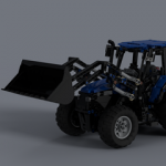
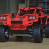
Hi! It's been quite a while since I managed to put something together and even longer since I managed to put it "on paper". I'd like to present you my latest, and already an old MOC, may it rest in pieces, The Red Pitbull Terrier! At first, this one was supposed to be my noble steed for the unfortunately canceled winter trial truck (kinda) competition organised by our national LUG. Stressed out due cancelation, this horsey grew bigger and fatter than it was ment to be for the actual race. I admit, it is rather fugly, but it was a lot of fun to build and drive also. I am especially happy about how did the suspension come out - the tracks adapt(ed) to the surface very smoothly and there is no bending of the road wheels towards the outside. Thanks to our EB colleague Kelkschiz and his I learned, that what I've built is called a Christie tank suspension . As a keen eye will certainly notice, I used the small shock absorbers with normal springs. Only when I put the cab on, I learned that the front road wheels had to be suspended on hard springs, because the weight of the cabin was pulling the whole truck's front down. My intention was, to build the tracks like a module with spring inside this module, which would then be attached to the hull. After several trial and error iterations, I abandoned that idea, because I didn't manage to eleminate the bending of the road wheels towards the sides of the truck. I ended up attaching each road wheel one after another, kinda like stitching and prepared me quite some "fun" for disassembly As for the hull, I thought I managed to seal the bottom and the sides of it quite well, but that damn half melted snow reached every dark corner of that ogre anyway! As you can see on the photo below, I decided that this puppy should run on four PF XL motors, with all sprocket wheels driven. The motors were geared down just a bit (12/20 -> 1/1.67). I really recommend those "new" wheel hubs for mounting the sprocket wheels - they hold as Kragle and I don't recall the tracks ever slipping of them, as it seems it often happens when sprocket wheels are mounted on axles only, as they tend to bend. As you can see, I built some kind of a gutter for the tracks , so that no return wheels were needed. That two stud wide gutter in combination with the mudguards also kept the tracks tucked in nice, preventing them to slip off. Some transversal girders were also used to make both sides of the suspension sturdier. A nice, warm pit remained in the center of the hull for two AAA battery boxes. Two sets of 63 tracks were used. The motors were connected in pairs, each pair to its own V2 IR receiver. The receivers were placed under the hood of the cab, therefore a fake cooling fan. Although the tracks tend to slip, I decided not to mount any transversal ribs on them and went for a tight fit with the muguards. So here it is, with some accessories to make it look badass - at least that was my intention . Final dimensions are approximately W/L/H = 48/25/26 studs. Weight: 2.3 kilos. Two sets of PF LED lights were used, each powered by one of the BB's, so they were lit all the time. I tried to make the cab look a bit like the older tracked trucks that goooooogle provided me with. I had those transclear dome pieces for a while so I tried them out as a bulb for the lights. I still can't say whether I like the outcome or not. Can someone please explain why would somebody need turn signals in the middle of Syberia??? I sure can't say :laugh: ! The cab was somewhat fun to build because it starts with even width and ends with odd. Lately I really like Technic creations to be manned, so there are my three brave soldiers, kicking winter and bora in the face! I hope you like it, otherwise feel free to rip me apart P.S.: Yes, there is . I was, again, foolish enough to edit the video along with music that is under copyright, so the actual music you'll be hearing is just barely coherent with the cuts... I recommend listening to the "original" music which should be in the video, but it got shot down due forementioned world of legal stuff etc... I provided the link at the begining of the video. I must also add, that this baby was named after that song...I hope this little naivity of mine won't degrade your opinion on this build.Cheers, miha P.P.S.: I hope my "hero-doesn't-go-pro" didn't make any of you sick because of all the shaking... My fair lady provided me her LG G3, which I abused on this torture tool Thx baby. -
Put this moc together on the weekend, slowly making improvements to it (cleaning up lines, etc.) Inspired by K.S. Robinson's Red Mars novel. I have posted this to cuusoo so if you like it please support, or let me know how you think I could improve it - Thanks! http://lego.cuusoo.c...deas/view/35293
