
gyenesvi
-
Posts
2,396 -
Joined
-
Last visited
Content Type
Profiles
Forums
Gallery
Everything posted by gyenesvi
-
General Part Discussion
gyenesvi replied to Polo-Freak's topic in LEGO Technic, Mindstorms, Model Team and Scale Modeling
That seems like a weird part, not really the one that I would have picked as the most important missing one from the technic selection.. I wonder what's the use case for it that cannot be built from the 2 parts + axles that exist already. Where did you find those use cases? Do you have some pictures? -
I like how light-weight this build is, and the fact that it uses only one Buggy motor that's not built into the rear axle! I have been wondering how those motors could be used in a more realistic drivetrain setup, as they seem pretty long and optimized for direct drive to the wheels. So this build kind of proves what I suspected that if you build it into the middle of the chassis in an upright position then it will unfortunately take the middle of the cockpit.. But still a really cool one!
-
That's just too cool! I like the simplicity of the solution, and how accurately they all score :)
-
Well, looks like I know what my first build will be for the Buwizz and the two motors that are supposed to arrive tomorrow :)) Can't wait to test them! I like how clean the looks ended up, smooth shape and the black color is great with some red accents. Suspension looks really bouncy! Did you have significant wear in the drivetrain?
-
42126 - Ford F150 Raptor
gyenesvi replied to Ngoc Nguyen's topic in LEGO Technic, Mindstorms, Model Team and Scale Modeling
That's more like something I was expecting from the real one, thanks. I understand that in lego, using the ball joint simplifies things, but a similar version with longer links and a U-joint more forward could have easily been achieved with the ball-joint technique as well. Not sure what stopped them from it. It would have been nice to get some of those 9L links in the set for example.. -
I did think about it for a while, but could not get a solution from the Defender parts. With using other parts as well it may be possible to make it 2 studs narrower while keeping most of it, such as the middle part and the suspension link mounting points (just modifying the ends of the axle), but one difficult point I see is the 6L steering link. Unfortunately, you cannot simply replace it with a 5L, as there is no such thing. There exists something similar on Bricklink, but it's more like a regular liftarm, and the problem with it is that it's not narrow in the middle (like the 6L link), and it would collide with some parts as the steering rack moves and the wheel hub turns. It's a shame that these links don't exist in different lengths, it complicates things so much. I guess you could try to redesign the whole axle, but you'd want to keep the suspension mounting point, otherwise the whole chassis would need to be modified.. Making it 2 stud narrower would look somewhat better with thinner tires, but the realistic look would need 4 studs narrower I guess. Even if that was possible, it would get the wheel a bit too close to the suspension link I'm afraid. I have tried a couple options, here are some renders I made. Although they look nice from the side, unfortunately, they all make the axle look even wider, as the outer edge of a thinner wheel will be roughly the same as the Defender's, and the inner edge will move further out, since the Defender's rim is deep, but the rim that you can use for these is not. Old foam tires look really good: Zetros tires are not too bad either (although that's not really thinner): And finally the buggy tires, they are a bit too small I think (5mm smaller than all the others): Thanks, glad you like it!
-
42126 - Ford F150 Raptor
gyenesvi replied to Ngoc Nguyen's topic in LEGO Technic, Mindstorms, Model Team and Scale Modeling
Curious what you think when you build it. Here's what I found after building (just the technical point of view): - the whole front axle is very loosely attached to the chassis, and is wobbly as hell, although I can see a very simple and obvious option to fix it. It's as if they forgot about it. I checked several times that I did not forget something, and I had no suspicious spare parts left. Anybody seen the same? - the rear axle is fixed to the chassis with complicated half stud offsetting. The instructions say as a note, that the designers had a hard time placing the rear wheel properly. The half stud offset is needed because the ball-joint at the rear axle has a steep angle, which causes about a half stud offset forward, and this needs to be compensated. I wonder if this is realistic, because if the whole rear suspension link was longer, it would not be so steep, would not cause a noticeable offset, and there would be no need for that half stud offset complication. I've seen other raptor builds with longer rear suspension links. Anybody knows which one is more realistic? - the rear suspension uses soft springs, it feels a bit wobbly too. The rear axle is unnecessary bulky again, with little ground clearance.. And when trying to build something else from it, it dawns on me the that there are no lights in this set.. -
Thanks :)
-
I still don't think it's connected. I think the following is happening. At the start of the transformation, the drive motors are positioned such that the two feet are aligned, so that the robot is standing firmly on both legs in the beginning/end (not tilted left/right). To make this happen, the car might need to drive a bit with one rear wheel, to position the motor, and in turn, this turns the front wheel. When the robot stands up, the front part snaps into place, and straightens the wheels. If this is the case, really well executed mechanism! I'm curious! The way I read the rules, it is allowed to do the transformation in multiple programmed steps that involves the repositioning of the drive motors, so this would be permitted.
-
That transformation looks pretty awesome! Well I can clearly see two legs made out of two motors, that are driving the two rear wheels and the walking at the same time. I can also see the transformation motor in the middle of the torso. My best guess is that the steering is not controlled by a motor, but it's just turning free, and since the two rear wheels are driven independently, it has kind of a tank steering, which is amplified by the free turning front wheels.
-
Thanks for the tip, I guess avoiding sudden changes is beneficial altogether, as according to my experience, those are the moments that can put high stress on the drivetrain and break things..
-
Thanks for the response! I have ordered a Buwizz and motors, so maybe they arrive together with the updates :) Am I correct that if I use power curves in the app, to reduce the voltage and hence the speed of the motors, that also reduces the chance of triggering the protection?
-
Thanks, glad you like my builds! Indeed, I like to build suspensions.
-
[MOC]◄Hummer H1 1992►[2021]
gyenesvi replied to Michael217's topic in LEGO Technic, Mindstorms, Model Team and Scale Modeling
Looks really great, nice combination of technic and system! I have been playing with the idea of a hummer for a while too, but more along the technic line. I wonder if using plates for the bodywork adds much weight. Are the doors fully brick built, or are they like hollow under the plates? How much does it weigh altogether? -
Does anyone know if Buwizz 3 app already supports moving PU motors with slow speed and max power (like the Technic hub does)? And what is the latest status for the support of servo steering with the PU L motor? Is it working smoothly in the app already? @Zerobricks maybe? I can see in the Buwizz protocol that there are modes for normal power control and speed servo control, so the HW should be able to do it, was just wondering if the app actually uses them already, as I remember some discussions about not all being supported in the beginning. I'd also be interested in the resolution of issues reported here when running 2 Buwizz motors from 1 Buwizz cut down the whole Buwizz and people seemed to be unable to revive it. Has that issue been resolved? Thanks!
-
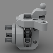
Here's a better render of the rear axle mounting, to show where it can pivot to tilt sideways. The other end of the olive green beam is attached to the chassis with a frictionless pin, so it also allows a bit of wobbling to help the free articulation.
-
Wow, that's a pretty interesting mechanism! I think compared to its complexity, the build is actually quite compact (it's pretty dense). It could fit inside a big yellow bulldozer :) What's the problem with the braking system? Is it not possible to control it gradually enough?
-
Thanks, glad you enjoyed it! Yes, the rear axle does have articulation, the two sides can move independently, it's not just a trailing arm, and not just the admissible wobbling of lego parts (but that helps too). The reason why it can articulate, is that because the links (olive green ones on the image) are mounted to the rear axle with a 5L brown axle with an end stop, on which the links themselves can rotate sideways (it's a bit hard to see on the image as it's dark, maybe I'll try to do a better render). Thanks a lot! About the battery: originally I wanted it exactly as you say, but there were quite a few problems. The main one is that I had to place the gearbox motor into the trunk, as there was no place elsewhere and it also had to be routed into the gearbox. It's a pretty problematic issue in this set, because with this M motor for the gearbox, you have to insert first a 3x down-gearing, then a clutch for protection, and then and end stopper before you get to the orange shifter (if you want it to be safe and controllable with the stock app). Second, the rear suspension springs also take up space in the trunk, so the battery would have to be lifted too high. And there's another minor problem, that in the app, the battery's rotation sensor is configured in a standing position, so if you put it flat it will keep screaming that the model is tilted too much. So I gave it a try in the beginning but did not pursue this too much, just put it in a standing position, this way at least it also constitutes to the stability of the roof bar structure. It might have been misunderstand-able because of the render showcasing the bodywork, but unfortunately it's not the whole body that can be detached as one piece (I think that would require more connector parts to be able to build separately as a solid unit), just the hardtop (roof and rear windows). True that the bodywork is built in large modules (like the sides, fenders, tailgate, hood) but it's not like some of it can be easily detached and replaced (for example taking the doors off is not easy, but at least they are solid).
-
[MOC] Jeep Wrangler
gyenesvi replied to Daniel-99's topic in LEGO Technic, Mindstorms, Model Team and Scale Modeling
Glad to see that my model inspires others! Nice build, the general shape looks good, although I have to admit that it feels a bit unfinished. But I guess you were not going for the looks but the functionality and keeping the weight down. I like the chassis, the suspension with those long shock absorbers should be much easier to build and make it smooth and largely articulated (it reminds me that I should start doing more non-alternate builds). Those tires also look good on it, what are they? I guess some custom RC tires, something like 85mm ones? I have seen a video of this in your long review post in the Zetros mod thread (maybe would have been better placed in the original Zetros thread to get to the right audience, but I'll admit that I have to agree with some points you made there). Anyway, it seemed to drive quite well, you should post that video here as well. -
Thanks, glad that the design process was useful! Actually, if you take out the red gear from the middle that connects the two sides, in low gear, you immediately get that Lego-AWD scheme! If you replicate the 2-speed gearbox to the left side as well (just need to insert two more gears), then you'd even have it working in both hi and lo gear (obviously by losing the RWD/AWD switch). So in essence you'd only need one blue 20T clutch gear as extra part :) Thanks a lot, I really appreciate that. Indeed, I like to get the max out of the concept I have in mind for a certain build. Luckily, with an alternate build the resources are limited, so it does not take ages to finish a model :) Thank you all guys! I am happy that there are so many nice alternates in this short amount of time already, it definitely helps make the set more popular!
-
Hey Guys, I'm back with my second alternate model of the Zetros set (42129). As you might remember from the presentation of my Unimog alternate, I was originally entertaining the thought of rebuilding the Zetros into a Jeep, but I passed since Tim has already built one. However, as I kept thinking of how I would do it, it became clear that I had quite different ideas in mind, and it was just too tempting to do it, so I gave it a go. Here I will write down the design process as that seemed to be something interesting for you guys in case of the Unimog as well, and I also prefer such presentations. Features - 3-link floating axle suspension with Panhard rod at the front - simplified rear floating axle suspension with 2 links of limited degrees of freedom and a Panhard rod - 2-speed gearbox with coupled RWD/AWD selector (hi gear is RWD, lo gear is AWD) - smooth and highly colour consistent bodywork - openable doors, bonnet and trunk - detachable hardtop - detailed interior with green accents, built seats - detailed engine, snorkel, minor extras (roof rack, jerry can, fire extinguishers) Here's a real 2-door model in dark grey color which I used as a visual reference: I also used a blue print to roughly set the proportions in a 1:10 scale. Bodywork Interestingly, this model started out from the bodywork, which I don't do often. As a fan of Jeeps, I have long been wondering what the best ways are for replicating its characteristic details, such as the hood and the grill with Lego parts. My Willys Jeep (alternate of the Defender) uses system parts for the (flat) hood and a simple vertical grill, but I wanted to build one with technic panels as well, replicating the slanted surfaces. I have seen two major techniques, one with the long wing-shaped panels (such as the models of @Madoca 1977 and @rm8), and the other with the long curved panel, mainly the classic model of @Sheepo. Since this set has those curved panels in DBG, and the wheels are about the same size as on Sheepo's model, I was wondering if a similar front could be built from the set, especially the angled placement of the curved part, along with the downward slanting of the whole hood, which also needed to be openable. It turned out that with quite a few alterations here and there, the hood could be built, and even better, they could be built using a few large panels only, which makes it look more clean and uniform.. Some arches needed to be redesigned, and the whole became 2 studs narrower, but the proportions worked fine. Then I moved on to the front and the grill, where much more redesign was needed due to different parts available, but after a few iterations with increasing the width and height of the vertical 'bars', I found the one that fit nicely with the smaller lights in the set and the newer curved small panel extenders (and as far as I can tell, newer Jeeps has such bigger grill, so it seemed fine). From there, I moved on to the sides. I knew it was critical to use the BDG panels carefully, because otherwise there would not be enough DBG beams to build the whole body, and I wanted a clean and colour consistent body. I quickly concluded that the doors can easily be built with the large panels, and the windows can also be built with the DBG connectors. The next critical point was to use the thinner long DBG panels in the rear part above the fenders. The difficulty was that they only left one possibility to mount the pieces of the fenders, so I had to use all those black angled beams there, and I had to build the fenders a bit wider so that I can actually connect the two ends to make it a stable piece. Fortunately, the wider fenders also made it possible to build the front ones from black beams at the same angle, even without more available angled beams using triangulation. The last critical piece was to use the small BDG panels in front of the doors, which just fit there tight. If I had to build that section from beams (as I started out), it would have cost too many beams and connecting them to the chassis would have been difficult as well, but the panel solved both problems (unfortunately, it has a drawback as well, which I will cover later). The remaining DBG panels were used in the back, also allowing for an opening trunk. The last tricky part was the rear corners with the lights. I wanted to make them more rounded with the curved panel extenders, but they would have screwed up the proportions, so I just used a slightly curved system brick to give it some curvature. Also I managed to use the black arched beams to replicate the characteristic rear roll bars, and the black tubular parts to build the roll cage, along with the 15L flip-flop beams, which proved to be critical for mounting the roof. The many flat black panels of the set were enough to build the whole roof, along with the side windows in a way that the whole hardtop is detachable from the roll cage as a single piece. Later, when it was more clear what parts remain, I also added the two bumpers, and even a nice snorkel and minimalistic roof racks were doable to give it more interesting details. Gearbox After being satisfied with the rough bodywork, I started designing the functional parts, which I also wanted to put emphasis on, since that's what technic is all about. However, since my Unimog alternate was about the suspension, this time I wanted to focus more on the RC gearbox and build a less articulated suspension which takes less space. I have been tinkering with the idea of a coupled 2-speed gearbox and a central diff-lock for a while (and @Pattspatt also teased me about it), but I never managed to design a compact one, where the drive motors are also placed conveniently. When I looked up a Jeep Wrangler drivetrain, I found this image, which was particularly interesting for me because of the front wheel drive that can be decoupled. Being offset to the side, I thought this could actually be nicely reproduced with lego clutch gears (something similar I already did with my Willys Jeep alternate, not knowing that it's done similarly in real life). After a lot of juggling with the placement of the motors and the gearbox components, I came up with this quite compact drivetrain setup with the gearbox inside the 11x7 frames, which not only includes the drive motors, but the steering motor too (later on that as well). The key ideas regarding the overall chassis structure are the following. First, I use a simplified (limited degrees of freedom) rear suspension, which requires only one CV joint, which makes the rear part of the drivetrain shorter, making more space for the gearbox, which is placed a bit to the back. Second, I placed the motors to the front of the middle section, and use the back of the motors as the mounting point for the front lower suspension links. Thus, the motors play a major structural role in the chassis. Here is the central part: And here is the whole drivetrain without the motors and the frames: As you can see, the rear part is short, and the front is offset to the side, and can just be routed between the drive motors, under the steering motor. Another interesting thing about it, is that it actually has two shafts (yellow axles at the front) coming from the two drive motors (but they are coupled by the red gear in the middle), and one of the shafts powers the 2-speed gearbox, that then goes to the rear axle, and the other shaft powers the the front axle, so the front axle drive does not pass through the gearbox, as it's only active in low gear. The orange selector switches both the gearbox and the RWD/AWD switch at the same time, activating the front of the drive train when low gear is selected. As with my Unimog, the placement of the gearbox motor was again difficult, as a lot of additional elements (end stoppers, clutch gear protection, down-gearing) need to be placed, so the gearbox motor had to be routed out to the trunk. Suspension As I outlined above, the rear suspension is a somewhat simplified live axle. I saw this trick first in @nico71's Ford F150 alternate, but builds of @rm8 use it as well. It is like a ball-joint based suspension, but without the ball-joint as support that prevents the axle from rotating forward/backward. In case of non-motorized models or smaller RC ones with less powerful motors, the joint itself is enough to keep the axle from rotating, but it was not enough in this case (the coupled motors could just rip apart the driveshaft), so I had to fix it explicitly. I opted for a suspension link that does not let the axle rotate forward on the far end, only tilt sideways (not using towball pins, just regular axles). This setup provides strong enough support to prevent the torque from ripping the driveshaft apart. A Panhard rod further stabilizes the axle to prevent sideways movement. Unfortunately, it's still not as solid as a ball-joint would be, and does not relieve all friction from the driveshaft. On the front, I used a similar 3-link suspension as the Unimog, but I had to move the Panhard rod behind the axle as the space was even less in the front, and managed to move the springs further in, giving it a softer and longer travel. It actually came out too articulated and had to be limited, as the wheels hit the fenders. Also, I used a better steering geometry than the Unimog (no anti-Ackermann geometry), and the max steering angle became very good, too good actually, as the wheels hit the bodywork at max angle, and can get stuck in it, so I limited the angle a bit, but is still better than the Zetros (the limiters are just half pins, which can be taken out to get a lot of steering angle, at the cost of risking the front wheel getting stuck in the body at max angle and max articulation, but work pretty good on flat surface). So the suspension is not bad actually, limited a bit by the bodywork, but the model still drives around quite okay on real terrain. Also, I wanted to experiment with a different steering setup, not placing the steering motor onto the axle. As said above, I found it a nice place between the drive motors, and using the CV joints there was just enough space to route it to the axle. It works okay, however, the two joints already introduce some lag in the steering, which is most noticeable when trying to automatically return to center, it does not center totally. But it's still okay and can be controlled with fine adjustments. Interior As the seats in the Zetros set were too small for this scale I needed to build bigger ones. Since I did not want to use the green beams on the outside, I used them as accents on the inside, they were enough to build seats and to be used in the middle console. I entertained the idea of making the steering wheel functional, since the steering motor is not on the axle, but there was not enough space to route it to the steering wheel, and furthermore, the curved panels used as a dashboard just block the way, and otherwise they are important structural elements that hold the front and the sides, so I did not want to alter them. The battery is placed between the B columns, as there was no other convenient place, and there it's easily accessible. The seats can be folded forward, to give room for replacing the batteries. The engine details are just some imaginary ones built from the remaining parts (nothing working). But the snorkel tubing continues on the inside :) Here is the whole chassis with the interior: And here are a few more renders and photos of the complete model, but much more is available on Bricksafe. Building instructions are available on Rebrickable. Let me know how you like it! Cheers, Viktor
-
Congratulations both on the channel and the new house, I know it's not easy to find a good one around here nowadays. Building a new lego room must be a lot of fun (and work)!
-
This is a solid alternate! Looks great, and I like the repurposing of the available functional elements. Moving the raisable axle to the rear is a nice modification, and the reuse of the hooks and cord is also a smart one :)
-
Philo's home page contains custom Studio parts for the Robot Inventor electronics: https://www.philohome.com/studio/packs.htm I also often use Studio to design the bodywork as it's much easier to lay out the shapes by building "in the air" when the proper support is not there yet.
-
That is true, I only meant situations where you have an axle hole at the end of one of the beams you want to connect. That's also an interesting usage, in a way the opposite of what I meant (I meant putting the axle end into an axle hole, and using the other end as frictionless, while you use the axle end as frictionless connection).