
gyenesvi
-
Posts
2,396 -
Joined
-
Last visited
Content Type
Profiles
Forums
Gallery
Everything posted by gyenesvi
-
 Yeah, that's kind of what I meant by pimped up. Not copying the model, but kind of redoing the whole idea with more accurate technical details, a different approach to looks, and without the expensive license. I do think that's a useful direction, what I found weird is the timing, though I guess one could not say that it would violate anything. It made me curious though how much time is required to redo an idea, it seems to me that this was pretty fast (I am guessing it was only started when Lego announced the CAT).
 -
I agree with this. I think continuity of lines and surfaces is what's more important, not covering up all holes. For this reason, I am not a fan of surfaces tiled with panels in all angles (that look like broken china), not because there are holes in between panels, but because there is a lot of discontinuity both in the surfaces and in the contour lines. Sometimes I even find that leaving bigger holes can result in a more smooth overall look. That said, flex axles can also be used the wrong way I think. I never really liked them used as wheel arches for example, because although the shape of the arch is good, it often becomes disconnected from the rest of the body. An exception is when the whole body is made of contour lines only using flex axles, then there is a uniform look. Nonetheless, I think flex axles can be mixed with panels here and there with good results where the two styles don't collide visually (for example the halo of an F1 car, or things like A-pillars on a car, maybe even when the paneling gives an approximate contour, and the flex axle emphasizes it further with a smoother version).
-
Wow is this something recently released? If yes, how come that it's released just after the Lego version? Is CADA now making pimped up versions of Lego sets? Not that I don't like it, it's just a bit weird. But sure it has a number of pretty interesting features. Besides the subtractor based drivetrain (are the top sprockets driven?), I like the use of micro motors for the blade tilt. Does two of that have firmly enough power for the task, or are they just okay-ish? Looks are also nice, though I never had problems with the Lego one. The double-sided controller is also an interesting one, and this would be a really good parts pack for CADA electronics.
-
Another small update. I have swapped in a Technic Hub in place of the BuWizz and the gearbox motor in the back (the framing is not so elegant, but managed to make it solid thanks to some flip-flop beams), since the BuWizz is not able to control the gearbox, and the steering is also problematic for now. The Technic Hub also fits nicely, although the performance suffers significantly. At 7.2V (with rechargeable batteries) it is quite sluggish in high gear. A 9V it is okay-ish, but struggles a little in high gear when turning. Low gear works well though. Because this 3x up-gearing ratio may be too much for the single XL motor, I also tried a simpler gearbox, with a 1:1.66 gear ratio. Obviously, that way it works much better in high gear as well.
-
As far as I know 1.9" tires fit these rims (that's the inner diameter, the outer could vary); though I haven't tried yet. But there's a thread here somewhere that contains a lot of info about 3rd party tires and their compatibility.
-
Thanks, it will look nice alongside the Bruiser build :) And I think there's plenty of potential for adding extras if you have more parts available.
-
Thanks, glad you like it, cool mods and nice photos! Sure, some RC tires would make it look even better, there are a few available on RC4WD for this rim size I think.
-
Does anyone know if there's a way to control a 2-speed gearbox with the BuWizz app? I did not find a way for it, not even a special module; I assume it's still under development. I tried to use the steering module with a non-centering lever for this, but with no luck, I could not calibrate a second instance of a center steer module. Can there only be one such module in a control profile? What if I have two servos for two axles and I want to control them independently? Also I am having issues with the steering module itself. First, the movement is quite jerky compared to the Technic Hub with the Control+ or Powered Up apps. I tried to adjust the basic parameters with not much change. I didn't dare to change the advanced parameters (custom steering options). Has anyone played around with those parameters and managed to get a smoother steering? Second, it sometimes stops steering while driving and afterwards recalibration fails too; it says it is done, but it does not return to center in the end of the calibration sequence and does not move afterwards when I start to drive with the profile (the drive motors work). I also tried restarting the app and removed and added the steering module without any change. Did anyone see similar issues?
-
I managed to add an RC gearbox with 3:1 gearing ratio, and a BuWizz to the back in a fairly slim overall packaging. This is where it stands now, I have updated the initial post with the details of the gearbox.
-
[WIP] Red Coupe RC
gyenesvi replied to Daniel-99's topic in LEGO Technic, Mindstorms, Model Team and Scale Modeling
Indeed much better this way! -
I have updated the initial post (marked by the date) with some progress on the rear axle and the driveshaft. I will keep updating the initial post like this to have a continuously readable flow, while I'll always post the latest status as a new comment. The current status is this (only showing the driveshaft and the two axles with the motor assembly hidden):
-
General Part Discussion
gyenesvi replied to Polo-Freak's topic in LEGO Technic, Mindstorms, Model Team and Scale Modeling
Indeed it seems like at least 9 studs diameter, maybe even slightly more. But that's 9 * 8 = 72mm at least, which is 10mm larger than the Arocs wheels if I'm right, more like the recent buggy tires (75mm). I wonder if these tires would fit on the Raptor's rims, that would be cool. But as you say, these rims are great for vintage cars, which is cool :) -
Thank you! Yes I built this, works smooth, it really feels like the axle is floating :) Do you mean the tie rod of the steering? Since the tilting of the hubs is very minimal, and those pins are frictionless that have some play anyway, there is absolutely no stress or bending there. I think it would even work with friction pins to further reduce the play in the steering system.
-
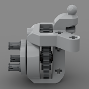
Hi Folks, As you may have guessed from my previous posts of my models here, I like off-roaders, including classic cars using live axles, so naturally I tinker a lot with various ideas for building them. This time I'd like to work on some mid-scale 4x4 cars, by which I mean wheel sizes in the range of 60-80mm, with 11-13 wide wheel bases, because that's a reasonable scale for lego electronics, things don't get too heavy and bulky yet, but still challenging features can be implemented. Many people have built great models before me on this scale, I especially like the chassis designs of Madoca, RM8 and Sheepo because they are compact, yet packed with interesting suspension and drivetrain features, besides nice bodyworks. However, their models are from the PF era, and now we have PU electronics and new parts related to that (such as CV joints, heavy-duty differentials and planetary wheel hubs), and I'd like to design my versions using these parts as well. I'll probably end up with a few different variants; for example axles with planetary wheel hubs / regular wheel hubs / built wheel hubs, 11 or 13 wide axles, various motor and drivetrain setups, with or without gearbox, manul vs RC gearbox, various suspension geometries, BuWizz battery vs Technic Battery, etc. Just like some of the above mentioned builders' models, I'd like to keep things realistic where possible. By that I mean things like (somewhat) realistic drivetrain, (engine and gearbox placement), realistic steering setup (servo off the axle, linkage based steering), and a possibly clean interior (no motors or battery box in the middle of the cab). However, I'll probably also experiment with some less realistic arrangements as well (like drive motors at the bottom). I'd also like to have some other functional elements related to the RC functions, like the steering wheel or the gear stick even when it's RC controlled, but this is more like a bonus when possible. So without further ado, let's get started. The first step for me is to provide an acceptable solution to two issues: 1) building a compact front live axle using planetary wheel hubs and 2) a motor setup that could result in a realistic drivetrain and steering arrangement. Given the scale, I need at most 13 stud wide axles. Since the planetary hub can only be mounted with towballs when steered, and towball arms are very limited in lego, this gets tough, especially if I want to retain acceptable ground clearance. From my Zetros alternate models I have learned that tilted lower towball arms can work well and retain acceptable ground clearance. With 5L towball arms and a 3 wide differential between them, 13 wide axle is the shortest theoretically possible. So I had to find out if there is a stable way to actually build it (without becoming too bulky, which I don't like). Here is what I came up with: The key was to find a stable way to mount the lower towball arms under the 5x7 frame. The wheel hubs become a little tilted vertically, but it is unnoticeable in reality and does not effect the working of the CV joints. As you can see, there are connection points for 3 links, a panhard rod and a steering link. The axle is quite solid against bending, better than I expected. The spring is mounted with only one stud offset forward from the axle center (not possible right at the center), and about mid-way sideways from the center to the wheels. This results in quite okay articulation relative to the scale even with these short shock absorbers. Next up is the motor setup, which should ideally be above and behind the front axle to keep it realistic. As noted above, others have already made interesting setups before me that I really like and would take that spirit on. RM8's chassis uses a PF servo motor for steering in the front and a PF XL motor behind it for drive. Unfortunately, in case of PU the L motor that is used instead of a servo is 1 stud longer, and the XL motor is 2 studs longer, making this setup impractically long (the drive motor would end up inside the cabin space). Sheepo's chassis on the other hand uses a servo motor sandwiched between two L motors, which is compact length-wise but much wider. This is an interesting setup that I might try to replicate with PU L motors later, but for now I settled for one that's kind of a mix of the two: a PU L motor for steering and a PU XL motor for drive, side-by side, both of them offset from the center. Interestingly, the shape and mounting points of the motors allow to do this while retaining some symmetry although the two motors are different, while also leaving just enough space for mounting the shock absorbers of the suspension (and even the third top link and the panhard rod onto the bottom of the XL motor). A further advantage of this setup is that the steering motor is not centered but offset to one side, resulting in a more realistic steering linkage crossing from one side to the other. I did have to try quite a few variants for the linkage to arrive to this one that has the right geometry (minimizes bump steer) is compact enough not to collide with other parts, such as the panhard rod (which is preferred to be close to the front of the axle to avoid the steering linkage pulling the whole axle sideways), and the springs (which also need to be mounted in front of the axle center to allow moving the motor assembly as much to the front as possible). Furthermore, this collision-free movement has to be true in all steering positions and suspension compression states. The variant here has absolutely no collisions in any combination of steering / suspension positions and the suspension moves smoothly (built and tested in real life). I have tested the steering assembly and how it works with the PU app, it seems fine so far. The drivetrain will start from the XL motor on the back of this assembly, and probably go to the center and 1 stud lower with a 20T - 16T gear mesh. From there two more vertical gear meshes are required to reach the floor where the main driveshaft will be, which leaves room for some sort of gearbox as well. That's it for now as a start, I'll move on with the rear axle (and the driveshaft) next, which should be much simpler than the front. Update 2022.02.27 On the rear axle things are simpler, however, there is an important decision to be made: whether to connect the driveshaft coming into the rear axle with double joints, which would allow the axle to be level, or just a single joint, which would make the axle have a positive caster angle (in case of the front axle, double joints are necessary, the single joint would result in a negative caster angle, which is a no-go for me). The decision also has an effect on the way the shock absorbers need to be mounted to allow them proper freedom of motion. For now, I go with the single-joint option for two reasons: it results in a 3 studs shorter driveshaft (shorter axle base), and the shock absorbers can be placed lower, this way they won't protrude into the trunk. However, even having decided this, I still have two options: use the ball-joint part designed for this purpose, or not. Although the ball-joint simplifies things by eliminating the need for additional sideways stabilization, it has some drawbacks as well; it needs to be mounted in the middle of the chassis, hence it limits the options to build the middle of the chassis where the gearbox goes, it reduces ground clearance in the middle, and it uses a U-joint, which transmits power with a non-constant velocity (though not sure that would be noticeable at a small angle, and when only one joint is used). For these reasons, I decided to leave the ball-joint out, and test how the rear part of the drivetrain would work without it. I have not seen this technique used with the new CV-joints before, only with U-joints, but I have tested it in my Jeep Wrangler alternate of the Zetros and seems promising. On the actual axle, mounting the planetary wheel hub is not as trivial as mounting an older non-steered wheel hub because its connection points are not designed for slim axles. However, I wanted to retain both ground clearance, and space above the axle to be able to lower the rear part of the chassis. Here is what I ended up with. Because I left out the ball-joint, it will need a panhard rod to be mounted somewhere to stabilize it sideways. The hub mounting is a bit asymmetric because I shaved off some material from the rear end to give way to the shock absorber as the axle tilts (lesson learned from previous builds). As for the driveshaft, I'd like to start with something around the minimal length that's possible to achieve (aiming for short wheelbase 2-door models), that's why I went with the single joint option on the rear. Because I want to use the stronger new CV-joints instead of U-joints, that does pose some limitations on it, because there aren't many ways they can be mounted and connected in the middle. Here's what I'll go with for now, this has 26 studs from axle to axle (so the axle center distance is 25 studs). That results in exactly the wheel base that my Toyota FJ40 alternate of the Ford Raptor has. In the future, I also want to try the double-joint option on the rear, resulting in a more realistic live axle, but that may require a longer model (for example a 4-door body). Although this is 1 stud longer than the theoretical minimum because of the 3L axle joiner in the middle (could be a 2L as well), it leaves the option for a straightforward gearbox in the middle (two gears next to the joiner, and one stud on each end to mount the driveshaft). As a side note, there would be some ways to reduce this wheel base with alternative parts. For example, if the male part of the new CV joint was available with a 2L axle as well like the old CV joint, that could be used to reduce the shaft both at the front axle side, and at the chassis side in the front for example (I assume using the old CV joint is a no-go as it would easily pop apart in an RC build). That would still leave room for a gear on the rear part of the middle section to transmit drive from the engine (but without allowing the simplest form of a 2-speed gearbox). With the 3L middle joiner swapped for a 2L joiner, that would be a total of 3 studs reduction in the wheel base, which would even work for models on a smaller scale, like Arocs wheels. At some point, I might consider making those parts for myself by cutting some axles (if TLG does not release that part, which would also be useful for building a narrower driven independent suspension). Update 2022.02.28 At first I thought the chassis would only have room for a trivial gearbox with 1:1 and 5:3 gearing ratios, with the two shafts situated under each other in the middle, arriving to the driveshaft. However, I realized that with the current driveshaft length, there is just enough space for a 1:1 and 3:1 ratio gearbox using a 4L differential piece, where the gearbox is laid out horizontally on one side. This setup could work well with the planetary hub, as the 1:1 gearing results in very slow movement (with a lot of torque), thus a geared-up second speed is useful, so I went for this one as a start. This would result in a manual gearbox version, with the gearstick positioned quite reasonably in the middle of the cabin space. Furthermore, I thought the space on other side could be used for controlling the gear switching with the orange changeover catch piece and making it RC. I started wondering where I could put a PU L motor for controlling the gearbox. There seemed to be only one reasonable place, somewhere in the back and raised with one gearing to give space for the rear axle (the view is from the other side here). And then a nice idea struck! I could place a BuWizz right next to it, and connect the two to make a 7 stud wide assembly, just like the two motors in the front. So the next logical questions were: 1) can I frame this in a solid way, and 2) will this leave enough room for the rear floating axle to move properly? The BuWizz sits lower, so that's the critical one here. Moving it up one stud would not be a good idea because it would loose the connection between the two, and on the outer side as well. That connection on the outer side proved critical, as that's a great point for the rear shock absorbers to mount. Framing wasn't too difficult, and I was just lucky with the rear axle's movement as well. It's very tight, but it just flies. The back of the gearbox motor can also be used for mounting point for the rear panhard rod. On the rear axle I had to make a half stud vertical offset for the panhard rod to get to the right position. Because of the low clearance above the rear axle, the panhard rod could be placed only at the very end of the rear axle (actually, that's where it's most useful). Because of that, and because of the mounting point on the motor/BuWizz required for the springs and attachment to the chassis, there is not much option to move the battery and the gearbox motor further back (maybe 1 stud, but that would result in not so ideal mounting position for the springs and the panhard rod). I was a bit worried that this would not allow the seats to be moved back enough, but this setup is just one stud more to the front than my Toyota FJ40 alternate, in which it's pretty much back, so I think this will be okay. Here are more renders of the whole chassis with the axles. I have built this and gave it a test drive. I mean I tried to, but the BuWizz App doesn't seem to be prepared for this yet; I did not find a way to control the gearbox. The steering kind of works, but it is quite jerky (calibrated fine, latest app version, firmware updated). I tried to play with the settings a bit, but there was not much difference. At least I know it runs with a decent speed in high gear, and seems to have good torque in low gear. Because of this, I think for now I'll try to build a version with the Technic Hub in place of the BuWizz and the gearbox motor, removing the RC control of the gearbox (leaving just manual), and wait for the BuWizz app to be updated with the gearbox module. Let me know your opinions so far! Cheers, Viktor
-
Axle Collection Thread
gyenesvi replied to efferman's topic in LEGO Technic, Mindstorms, Model Team and Scale Modeling
Wow, that's a great part usage for the wheel hub, thanks! Also, the way that servo is squeezed in there :) Does the drivetrain skip sometimes at the differential because of it only being supported by the surrounding frame and maybe allowing for some more space to move around? Or is it solid enough for this amount of power and weight? -
Axle Collection Thread
gyenesvi replied to efferman's topic in LEGO Technic, Mindstorms, Model Team and Scale Modeling
Hmm, that looks interesting, nice compact design with that asymmetric drivetrain. The suspension linkage is also a nice one. I wonder how the front wheel is driven, is there a CV-joint in there right next to the diff without any support for the axle in between them? In that case, is the CV-joint held in place by the framing around it and the wheel hub on the other end? The wheel mounting is also interesting how it fits into such a small rim! Do you have more close up pictures of it? -
Oh, I did not catch from the video what parts could come into contact, indeed it's simpler than I thought, thanks for the image, nice mechanism :)
-
Wow I did not even know people would be building trains out of technic, including the rails, you have a pretty cool station complex there! I like the way they look and there are lots of cool functions to be motorized for sure. Just out of curiosity, what triggers that sideways tipping mechanism? It seems like something automated somehow?
-
General Part Discussion
gyenesvi replied to Polo-Freak's topic in LEGO Technic, Mindstorms, Model Team and Scale Modeling
Probably in most cases you could push it out from the other side, and once it's out a bit you can grab the stop and pull it out. Though there could be problematic rare cases when the other side is not accessible, like in other classic impossible-to-disassemble builds, and those cases may be easier to force out with a knife or something when it does not have friction.. -
General Part Discussion
gyenesvi replied to Polo-Freak's topic in LEGO Technic, Mindstorms, Model Team and Scale Modeling
This will be another very useful pin.. if it will have friction counterpart. And if it will also be available in 2L version (which I'd need more often).. It's a pity that we have to wait for the need in a Star Wars set to arise to actually have them. -
General Part Discussion
gyenesvi replied to Polo-Freak's topic in LEGO Technic, Mindstorms, Model Team and Scale Modeling
Yes, it would be useful quite often :) One of those parts that should logically exist.. -
[MOC] 8865 New Jeep RC
gyenesvi replied to mla2's topic in LEGO Technic, Mindstorms, Model Team and Scale Modeling
I also saw this already on Rebrickable, it's a cool remake, it could have been a great entry to the previous technic contest about studless remakes of studful sets. It's amazing how nicely playablemodel can be achieved with a lightweight body, one L motor and a BuWizz compared to a PU version. I like what you write about all aspects of the hobby, indeed, they all differ and are enjoyable! -
General Part Discussion
gyenesvi replied to Polo-Freak's topic in LEGO Technic, Mindstorms, Model Team and Scale Modeling
I also often have problems with that one, it's always in the way for something.. This has some truth as well.. They just got quite long over time. -
I was thinking the same when I saw the video, wonder how this will work inside. I guess that is why there are rubber pins on the tracks, otherwise they would never flip indoors, they would not have the grip to go up on the smooth surfaces, like walls.
-
General Part Discussion
gyenesvi replied to Polo-Freak's topic in LEGO Technic, Mindstorms, Model Team and Scale Modeling
My guess would be that they will appear in the next supercar inside the gearbox, as they probably make it run smoother. Also, in RC models to make the drivetrain smoother and put less wear on the beams (the teeth of these will not rub against the beams the way the bevel gears do). I wonder if they will release a clutch version of the 20T. I guess it's not possible for the 12T.