
gyenesvi
-
Posts
2,396 -
Joined
-
Last visited
Content Type
Profiles
Forums
Gallery
Everything posted by gyenesvi
-
 That's interesting insight, wonder how he put it together then (because I'm sure he did). I think it must be evenly spaced, because it is using a pulley wheel for the planet carrier, right @HorcikDesigns? The ring has 24T if I count correctly. Btw, I think the same construction would work with 4x 8T planet gears as well, I just tried and they would still be far from touching each other. However, there's no technic piece to carry 4 planet gears I think, the closest is this piece, that could carry 2 (unfortunately, there's no free spinning version of the 8T gear):
 -
Yeah, that sometimes happens, so by that line of thought I'm expecting a proper sized technic Jeep Wrangler and a classic Land Rover :) I guess I'll have to wait a few years though.. Ferraris and Lambos seem to get duplicated more rapidly in technic nowadays. Nice catch for this set by the way. Interesting reference by TLG.
-
General Part Discussion
gyenesvi replied to Polo-Freak's topic in LEGO Technic, Mindstorms, Model Team and Scale Modeling
Sounds good :) Thought I can live without the pink accents and the print on the tires (would look good but ain't gonna happen I think). And finally TLG could start making fender pieces that are better fit for SUVs and off-roaders (instead of only sports cars), where the top does not curve too much (2 studs) inwards onto a low hood, because it has to continue straight up, and where the bottom may curve inwards. I think this could be done with a flat panel piece that has a wheel-arch cut in it, that accepts a fender flare (like on the Raptor) that protrudes a bit out of the flat wheel-arch panel. And the same wheel-arch could accept fender flares of various styles.. -
Thanks again! Yes, because then that becomes the path of least resistance. Yes, that's exactly the same general principle, but implemented with rotation instead of an LA.
-
MOCs versus sets
gyenesvi replied to PlopiNinetySix's topic in LEGO Technic, Mindstorms, Model Team and Scale Modeling
I have a bit of a hard time interpreting the question of this thread. To me, the best MOCs are usually pushing the limits in ways that would not be acceptable in an official set, by cramming lots of stuff in using somewhat questionable techniques. So that by definition will not really be met by official sets. Instead what best official sets could do is provide clean solutions (by introducing new parts) to problems that could only be solved by such questionable techniques before. Now to me, the Zetros is a pretty bad example of that. It could have introduced new parts for building live axles in a more elegant way (for example the part that we are just discussing in the 'Technic parts that we would like to see' thread), but it did not really (except for the long CV joint, which also turned out too long I think). Instead they turned the Zetros into a giant gearbox with giant live axles. True that they did hard-coupled motors, that's a first (but not really an achievement). But that thing has basically non-articulating suspension, almost zero ground clearance, bad steering and is unplayably slow (that's the least of the problems though). On top of that, the gearbox switching is implemented with an M motor which does not have a rotary encoder, through a ton of gears and clutch in a very convoluted way. We could have just gotten a small angular motor in that set with a rotary encoder that could have been ideal and very useful for building gearboxes. But they spared that out of a 300 Euro set and dumped out all the not so useful M motors they had at stock. Also for me the looks are toyish, not really like a trial truck (just marketing). I don't think a good MOC would have these properties. If I view the set as a parts pack, then it's a good one though :) Or did you mean 'MOC-like' in a way that it over-complicates things because the right parts don't exist? Then, yes, the Zetros is like a MOC.. -
42164 Off-Road Buggy
gyenesvi replied to Ngoc Nguyen's topic in LEGO Technic, Mindstorms, Model Team and Scale Modeling
I love this; not only have some people built it already, but we also have crude building instructions for it before it hits the shelves! :D -
Indeed, both variations would be useful, and actually both of them (and even more variations) have long been listed in the first post of this thread ;)
-
Thank you guys all for the praise. I'm really glad that you appreciate the mechanical aspect of it the most. Thanks a lot, really appreciate that! It's really simple. Think about it like this: it could do both actions at the same time; the bottom end of the LA wants to fold the arm, while the top end wants to lift the whole arm when being extended. While it could do both, it only does the one that requires less force. So first it folds, but when that gets blocked (after it's folded all the way), it starts to lift. When lowering, it is reversed, because then the lowering of the whole requires less force, and when that's blocked, the unfolding comes. Btw, I forgot that I wanted to add a zoomed in render of the steering linkage, I've inserted it above.
-
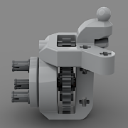
This is exactly what I'd find most useful for these hubs, looks great, and it's such a missing piece, and what's worst is that the Zetros had the chance to introduce something like it, but they instead made some super bulky axles.. That planetary reduction is also a nice design, what's the down-gearing ratio of that? I also like the buggy motor mounts, though that's a very specialized part.
-
Hi Folks, Finally, after a long design time on this one, I can show you my latest alternate build out of the Volvo Hauler (set 42114). I had long been thinking what to build out of this set, because as I was slow (busy with other sets) my first idea (the grader) was taken by others. Afterwards I had some crazy dump truck ideas, but convinced myself that yet another dump truck is not such an ingenious idea, and I finally got a hint for a tow truck. That sounded like a nice idea, because the functionality seemed to match the Control+ profile nicely, the extra function being the towing arm. So the search began for something real to model, and I quickly converged on Ford F350/F550 models as inspiration. Features Rear wheel drive with 3-speed automatic gearbox Pendular suspension with torsion bars on both axles Working inline 6-cylinder engine Towing arm with two-stage motion: fold and lift Openable doors, hood Interior with seats and dashboard Design process The design of this model started from the looks / body work. I found a few variations on the below Ford F550 and similar F350 models, and thought this could be doable from the parts, especially because the big fenders can be used in the front, and the rear one could have been built with the curved panels, and the overall shape is fairly blocky that could be done with all the big flat panels (I could make use of surprisingly many of the trapezoid ones). I designed the cab, the hood and front grille mainly (I could even throw in the stickered mirror plates as headligths), and it started taking shape nicely. After that I started with the internals. My goal was to build it with suspension to make it more challenging, to retain the 3-speed gearbox of the original, and to be able to implement some kind of a towing arm. Also, I was sure there would be plenty of space for an interior. As for suspension, the parts would only allow some kind of pendular axles, but to make them both pendular, I needed some actual damper. Learning from Egor's Dakar truck alternate build, I decided to go with torsion bars. Starting with the front axle, however, I realized a problematic point: it will be hard to make the wheels turn and articulate without getting stuck in the fenders; there would be only one chance; by keeping the scrub radius as little as possible, so regular use of portal wheel hubs were out of the question. I could have built it without using the portal hubs, but I did not want to have these large wheels simply attached to an axle, so I decided to try and make the front axle with the portal hubs turned flat (I knew there's no chance to make them driven anyway, not enough joints for that). I think that my alternate is the only one with suspended and steered axle that uses the fender parts as fenders.. The next problem was the steering mechanism. After some sketching, I realized that I can't just put the servo on the axle, because then the chassis rails have to become wider to allow the servo to tilt, and the wheels would simply get stuck in the chassis upon steering / articulation (even though the truck is wide, the wheels take much space). So I had to make the servo stationary, which was also favorable because it would hopefully leave more space for a working fake engine above. After a lot of juggling (some workable options ruled out because of too short cable length) I came up with the following configuration, in which steering is though a tight linkage, that allows the axle to tilt without introducing any bump steer (the linkage tilts exactly where the pendular axle does). Here, the servo is stationary, and the axle is mounted to it in the middle of the O frame and in front as well, while the steering linkage is behind the axle, and the torsion bar of the suspension is in front of it. As for mounting the wheel hubs, it was doable, though it's not my strongest build (held by 3/4 and half pins), but it does the job okay. It even has Ackermann geometry. The rear axle was really simple compared to the front, just a regular driven pendular axle, with some torsion bars attached. Next up was the middle of the chassis, with the gearbox and drivetrain. This proved to be the most challenging part, to fit it into a rigid framing, while also having the output for the towing arm in the right position. I had to alter the gearbox layout w.r.t. the one in the Volvo, as the Volvo has both its drive output and the dumper output somewhere in the middle, while I had to arrive more towards the back, all while keeping the logic of the layout essentially the same, so that the same Control+ profile can work with it. After a series of redesigns, the final chassis became quite compact and solid, with a nice structure. I could finally start adding the fake engine and some support structure to make the chassis and the body meet, and also make some internals. The many O frames helped a lot. And last but not least, the towing arm. At first I tried kind of a conventional setup with the linear actuators lifting the arm from the bottom, but that had two problems. First, as the actuators are pretty long, the space was really tight for them. Second, that would have only allowed me to lift the arm, but not unfold it (the first idea was to make unfolding manual). But I did not like this design, and started to think about moving the actuators out to the end of the arm and make them perform the folding of the arm (at this point I thought it's not so necessary for the arm to lift). But then I realized that by mounting the upper end of the linear actuators to a linkage, I could make it perform two motions at once :) But which motion would get priority and what would decide that? The answer was pretty simple: gravity will solve it; the movement that requires the least resistance will be performed. So it works as follows. When it's completely down, and the LAs start to extend, it is easier to fold the arm, as that's less weight. When the folding is finished and the folding part is blocked by the rest of the arm, then the LA cannot do anything else but lift the whole arm through the linkage, until completely extended. When lowering, the process gets reversed, because the weight of the whole arm is bigger, the whole thing lowers first, and when that's blocked, it cannot do anything else but unfold. The interesting part is that the raising changes if we put weight (a vehicle to tow) on it; then folding would require much more effort than lifting the whole arm, so in this case the LA will start lifting the vehicle. Exactly what's needed! All in all, at least there was some challenge in making this arm work in a playable and interesting manner, and I am quite satisfied with this simple solution, I'd even say I find it elegant :) And it looks good, like some solid machinery. Being an alternate model, the parts were limited (lack of joints), and so the driveshaft routing the power to the linear actuators ended up being quite long and loose in the air (going from the base of the arm up to the LAs directly), which is not the most stable solution, even though it never failed for me. However, I designed the model such that there's an alternative output from the gearbox to the towing arm that can be used (moving the lower joint to be exactly in the pivot point of the arm) to build it more stable if one has an extra CV joint part available. Here is a way how the driveshaft could be routed inside the arm that makes it much less exposed in the air (older joints could also be used). Here are some photos of the model in the wild. Of course I tried how it off-roads.. The performance is not great, it is obviously underpowered with the single XL motor, and while the suspension works okay, the bigger problem is that it is only RWD, and the tires slip quite easily and just spin under the vehicle, despite its weight. Many more photos are available on my BrickSafe. Building instructions are available on Rebrickable. Let me know how you like it! Cheers, Viktor
-
1:12 Audi S1 e-tron
gyenesvi replied to Zerobricks's topic in LEGO Technic, Mindstorms, Model Team and Scale Modeling
I know the fenders are not, but I thought the 3x13 panels are, because Bricklink said so, but I guess they were only in the Osprey.. Though they are available in dark blue :) -
I think in this case, the stop part would go into the pinhole of the 2x4 L beam on the top, so there would be no shortening of the axle if a 4L axle with stop would be used. Second, the other arm of the gripper is mounted on a 5L axle without stop, so its bottom end is exactly where a 4L axle would reach. So I don't get either why the asymmetry. If it works on one arm, it should work on the other as well. Or if they made the axle of one arm longer, why no make the other one longer as well using a 5.5 axle?
-
I can believe that it works in this application, but I think it's due to the circumstances: it's a light weight vehicle, there's not much down gearing after the motor, and the tires don't have much traction (it will never get stalled since it can easily spin the tires under itself). If it was a bigger/heavier build, 4-wheel drive, with large grippy tires, then I could easily imagine that gear connection skipping. But I could be wrong, just thinking that otherwise such gear meshes would work in other MOCs as well, but that's not the case (they typically have to be braced from both sides). The only thing I can think of why this may work in a more general setting as well is that this connection is at the very beginning of the drive-train, and if all the down-gearing is after this, then there may not be much stress on this one. Do you have some links to the motor/ESC you used? Are the motor mount holes 16mm apart? And what's that connector trick you use for the motor cables? Looks interesting!
-
1:12 Audi S1 e-tron
gyenesvi replied to Zerobricks's topic in LEGO Technic, Mindstorms, Model Team and Scale Modeling
Nice looking car, I like the shape, though it's a bit too many colors for me, I guess it's parts availability, but I think almost all black panels could be swapped out to DBG. Then it could even get closer to the real one.. The driveline is pretty interesting, those CV joints are cool idea. Are those rings half stud wide? Or a bit less? Curious how it will drive! -
Exactly! Something like that is Number 1 on my wishlist of connectors! So much that it's on the first page of this thread, in the connectors section ;) Although I think it would often be more useful with axle holes, at least the perpendicular one. I don't even understand how Lego got away without it so long, I could use it so often. Here's the bunch of connectors again, the bottom one:
-
This. Wonder how many small kids even know the brand? It does not seem too meaningful to license such a model to me. I don't think that's a selling point for the parents of such kids either.. But this might be an explanation, though not sure I get how such license agreements would work. Would they agree that Lego has to release a certain number of licensed sets, or what?
-
Interesting solution, though wonder why not do it with a longer pin to be able to fix it at the other end of the pinion gear as well, i would assume that such a powerful thing needs to be fixed properly from both sides. Would it work with a 3L axle-pin? (they have differing inner diameters)
-
42164 Off-Road Buggy
gyenesvi replied to Ngoc Nguyen's topic in LEGO Technic, Mindstorms, Model Team and Scale Modeling
Oh, that door solution also puzzled me, I could not figure how they get the friction, but now I see, nice catch! -
I do agree that some words may be a bit strong (I was also surprised to read "disgusting"). But different people react with different emotional charge to things, maybe he was disgusted, it's his right to be so, but he has to deal with that himself. But if all such expressions were moderated, that would also create a lot of unnecessary confrontation and policing atmosphere, so I think it's better not to expect such moderation but rather ignore the comment if we don't agree with it, or just say we don't agree with it without blaming the other person of anything, after all it's his opinion. Obviously, if comments would get really personal and use a lot of really strong language like swearing, that would have to be moderated. I think I've said enough, don't want to repeat myself, and sorry for getting off-topic.
-
How long has this been out as non-beta for both Android and iOS? I just realized it is out for iOS. Also, it is possible, that many users, like myself, are still using BC2 for the controller, and they will only move to Buwizz app once the controller support is out, and they will only be able to really test it out then. Unfortunately BC2 does not seem to develop further to incorporate this setting, so those who are using it still have the problem. So yeah, controller support would be good to have sooner than later.
-
Of course I predicted based on the previous occurrences that you would probably find it so, but as I wrote, that is your interpretation, not my intention, and I let that be your problem. Furthermore, I don't see how I would have dumped on my own point. You can have your own opinions as anyone else, I accept that. What you should not do is blaming other people for discomforting you with their opinions, as I do believe that is emotional manipulation (maybe sneaky is not the best word for that, I'm not a native speaker). And I haven't blamed you of insulting me. If anyone is dumping on their own point that's you; you advocate honesty and free opinions (just read that in another thread), but you in some cases take them as insult when they disagree with you.
-
I think it's not that simple. They'd have to check them for quality issues, make official instructions for them, which is still a significant amount of work, and I guess many C models we think are really cool would not meet their criteria. Also, many of the best C models are modeled after a real-world counterpart, and Lego could not release those officially without licensing.
-
Well, let me point out that being insulted is your feeling, it's not him doing it onto you; you interpreted it that way, every person reacts differently, and in my view grown-up people don't get insulted by such general statements. And just because you feel insulted does not mean that we don't not have the right to express our view. It's not other people's responsibility to keep you from being offended, it's your responsibility to handle disagreeing opinions around you. So please don't flip it back on other people (as I have observed that you have done this on several occasions), that's a very sneaky behavior. Thanks!
-
Thanks for the detailed answer about the custom parts. They look really interesting, wish I could buy some, especially those wheel hubs. What is the material of those hubs? Are they 3D printed or are they molded, or are they metal? Also very interesting that the other parts are made with silicone molding, that's something I have been looking into as well, seems promising technology, though would be a bit finicky to do at home.. Those white ones are the silicone molding shapes on the picture, right? As for the planet gears, do you mean the gears themselves are made of silicone, or did you refer to the molding shape? Dividing the axles of rotation of the steering and suspension can be indeed useful, but only works in non-driven front axle, as the drive joint can only work when the two rotation axles are at the same position, and I more often build driven front axles for the slower crawlers.
-
Technic General Discussion
gyenesvi replied to Jim's topic in LEGO Technic, Mindstorms, Model Team and Scale Modeling
One more note, I agree it's not a major issue, but I do see one kind of a concerning philosophical shift related to this in the past decades. I think B models incorporated / encouraged a core idea of Lego that you can rebuild it to something else, and that's shifted a lot with the appearance of collectible shelf queen series, not emphasizing the reusability of the bricks. Though the loads of people who nowadays buy lego and never build on their own, just collect them, probably also contributes to the phenomenon. I don't know if that was significantly different in the past though, I'd tend to think so, as when I was a child collecting lego for the shelves was not a trend around us.