

TechnicSummse
-
Content Count
249 -
Joined
-
Last visited
Everything posted by TechnicSummse
-
[WIP] 40+ km/h racer - need your help!
TechnicSummse replied to TechnicSummse's topic in LEGO Technic, Mindstorms, Model Team and Scale Modeling
Thats right... i did not want to talk about kingpin inclination, since it has nothing to do with just 1 wheel ;) Why did you draw my turning-axle completeley wrong? The turning-axle at my car is exactly as i did draw it... its angled backwards at the same amount, as my body is tilted to the front. And like this it hits the ground exactyl at the point i did draw in the image ;) By the way.. the turning axle mostly does not hit the center of the wheel like you did draw it... it mostly looks like this: By definition, caster is the difference between the point where the wheel hits the ground, and the point where the turning axle (imaginary) would hit the ground. For a positive (wanted) caster, the point where the turning-axle hits the ground, has to be infront of the point where the wheel hits the ground. And this IS given at my car -
[WIP] 40+ km/h racer - need your help!
TechnicSummse replied to TechnicSummse's topic in LEGO Technic, Mindstorms, Model Team and Scale Modeling
Well... phew.. its allways hard to tell people things wich they think they know allready... Again... i am a car mechanic master craftsman (think this should be the best possible translation to english for my job). I have to do with such things pretty often ;) This happens in cars only... did you see any parking bike with a straight frontwheel? I guess you will say now... all the bikes are inclined to the left side... and yes you are right... but this shows another point, i will explain. Like the caster on bikes is done, the wheel lifts the bike in straight position... meaning you have to push the bikes weight into the straight position. If you pushed a motorcycle you will know what i mean... the more you steer while pushing, the harder it is to go to the straight position again. I think what you mean on cars is because you lift the car while steering to the edges of the wheels, and it has its deepest point in straight position. The wheels want to go to the ground again... as you can see in the following picture (perfect paint skills ) If so... why do i have a fluttering wheel in reverse direction, as you can see in the video? Caster has nothing to do with the surface you are running on. Caster is by definition the difference between turningpoint and the point the wheel hits the ground. This does not change with changed surfaces. At the same time, if the wheel is lifted because of hitting a bump... caster does not matter at all... because the wheel has no contact to the road. In the image below, you can see my angles at the front: As you can see in the image... i have a huge caster with the turningpoint infront of the wheel. At the same time the caster is reduced because of the body-tilting... (maybe this is what @nicjasno meant). But like this.... i can realise the exact opposite of the "bike-problem". Like this, i lift the car, when turning the frontwheel. The weight additionally to the caster pushs the wheel to the straight position again. -
[WIP] 40+ km/h racer - need your help!
TechnicSummse replied to TechnicSummse's topic in LEGO Technic, Mindstorms, Model Team and Scale Modeling
sure... the wheels have a round profile... camber does not change anything at rolling resistance here ;) Did you see the video in my latest post related to my caster? -
[WIP] 40+ km/h racer - need your help!
TechnicSummse replied to TechnicSummse's topic in LEGO Technic, Mindstorms, Model Team and Scale Modeling
Hmm... i dont see, why you all think my caster is wrong... its just crazy :D I made a video again...i removed the steering lever, to let the front wheel do, what it would do while running. You can see what happens in wich direction... i think i made everything right here With the new steering setup now, i also got some ideas, how to suspend the frontwheel. But i still would see different ideas :) But then again the motors are part of the unsprung mass... The (relativly small) slack will be romoved with a hockey spring... when my order arrives :( This should be here allready 2 days. To the self centering... take a look at the video :D Wheels? Sounds like you want to mount 2 wheels at the front also? As i sayd earlier... this will result in 33% more rolling resistance. I would like to see a sketch of your idea -
[WIP] 40+ km/h racer - need your help!
TechnicSummse replied to TechnicSummse's topic in LEGO Technic, Mindstorms, Model Team and Scale Modeling
I know about that... i am a car mechanic and i lead a garage ;) The design is not meant to be like the one on a shoppingcart... but it has to have the turning point infront of the wheel...maybe you did not see it.. but there is also a caster at all... the whole body is tilted forwardly 3 studs, as you can see in the following pictures: All together this should make a realy stable frontwheel. Any idea, how i could achieve this with a 2-gear drivetrain? As mentioned earlier... i am happy to have a ~70% sprung weight now... and just ~30% unsprung (well i know this is still a lot...). I would need to undock the motors from the rear-axle... but this would mean a way more complicated drivetrain, meaning heavier construction AND especially producing alot more friction, because of more axle/pinhole bearing points and more gears required... I would create such a kind of suspension for a fun model. But 2-3 studs of travel means 3-4 studs of ground clearance... this will lift the center of gravity way to high... resulting in a unstable driving... and especially resulting in tilting to the sides with just 1 front wheel. This could be realised with 4 wheels... but then again there will be 33% more rolling resistance, wich i assume as one of the biggest torque eater at all. I would like to hear/see any suggestions here. If you like... feel free to pm me. I know... it can be changed easily... i just wanted to start testing with a bigger turning radius... since there is a 3 step servo at the rc-unit, i should be able, to do just small turns, also with a 3 stud long beam, if i move the steering-stick just a litlle bit to the first position. Not sure if you can see it properly in the video below... but it demonstrates exactly what i assumed yesterday: When steering the car tilts a bit to the side... this causes one of the rear wheels to lift from ground, and the supporting wheel to contact with the ground. Furthermore the supporting-wheel acts as lever, and also lifts a bit the second rear-wheel, to also loose grip. At first you see a steering to the right, with dismounted supporting wheel... followed from a steering to the left with attached supporting wheel on this side... i think you can see the difference... -
General Part Discussion
TechnicSummse replied to Polo-Freak's topic in LEGO Technic, Mindstorms, Model Team and Scale Modeling
Hmm, but how you know it really is lego? Could be some selfproduced stuff? -
[REVIEW] LEGO Classics: 8868 Air Tech Claw Rig
TechnicSummse replied to Sariel's topic in LEGO Technic, Mindstorms, Model Team and Scale Modeling
This was the first set i HAD to buy again after my dark ages. It was a christmasgift once, when i was 8 years old...but a few years later, when i became older...my mom gave it away to the neighbourhood... Now i own it again, and i love it... this is in my eyes still the best technic set ever. When i got my 8366 later, i started to play with the rc-stuff... and i will... one day... finish this "secret" project: Now i own PF-elements also, wich would make it a lot easier to make a rc-version of this beauty, but does new PF elements fit to this 25 year old model? -
General Part Discussion
TechnicSummse replied to Polo-Freak's topic in LEGO Technic, Mindstorms, Model Team and Scale Modeling
just enter "special" in the search in his shop.... red rims... 40€ one rim lbg axles... in 6/8/10/12 studs :D Strange things there... but... are those parts really lego? -
[WIP] 40+ km/h racer - need your help!
TechnicSummse replied to TechnicSummse's topic in LEGO Technic, Mindstorms, Model Team and Scale Modeling
@nicjasno Last week i made another video especially for you (and for me, to see what really happens with my car ) Please watch it at 0.25 speed setting on youtube. _____________________________________________________________________________________________________________________ Last week i also wanted to test my latest setup at full speed. I thaught i found a nice place for my testruns: It looks really nice ... if you are far far away... ... but if you take a closer look.... .... you can see... .... it is not the best place for a Lego high speed car to run... So i had to go back to my old testtrack on the "penny-market" parking. Performance was really nice... i had some nice results at the speed computer... but... i simply can not run it at full speed. I had a lot of problems with oversteering at 30+kph with the new frontwheel. That's why i decided, to rebuild my steering-system to something similar to the ones @Marxpek and @mocbuild101 used on their fast cars. Below you can see some pictures and a video of the new steering: The way i designed the steering now... i am also able, to use the speedcomputer at the frontwheel, instead of the rearwheels... for a more accurate measuring (some claimed about possible slipping at the rear axle ). Well... but sadly the new steering did not bring any better results. It is way more accurate, drives more straight... but still... at higher speeds it oversteers exactly as my previous steering-system. Every little steering results in an instant complete turn of the car. But i think i allready found the problem... i think the supporting wheels are mounted to close to the front of the car... and if they hit the ground, this results in a verry small turning radius like this. I will make some changes again, and hope for good weather tomorrow. -
Redneck Muddin' Truck
TechnicSummse replied to nerdsforprez's topic in LEGO Technic, Mindstorms, Model Team and Scale Modeling
They use modified original axles... that's why you see diffs ;) But they usually are locked. When driving in mud or loose terrain, you should not kill any parts with a locked rear axle. Locked front could bring some problems, thats right... but also just on harder, more grippy surfaces. I just saw your wheels slipping alot in the video, and you could reach a much better performance, if you would lock the rear axle (remove the diff). But still this is a nice car... and i like to see it is able to drive in the mud really ;) Lego IS meant to use outdoors! -
Redneck Muddin' Truck
TechnicSummse replied to nerdsforprez's topic in LEGO Technic, Mindstorms, Model Team and Scale Modeling
Not sure if he made it accidently, but this is usually done in mud-races. The inverted V-shape grabs much better in the mud. If you mount the tires the "right" way, the mud is pushed to the sides, like the v-profile on roads usually should push the water to the sides ... but in mud this causes the wheels easier to slip. If you mount them inverted, the mud wil be catched within the v-profile, resulting in a lot more grip. It acts like a barb (hope i found the right word with the translater :D) -
Redneck Muddin' Truck
TechnicSummse replied to nerdsforprez's topic in LEGO Technic, Mindstorms, Model Team and Scale Modeling
Differentials in a mud racer? :D You should have direct drive at all axles... maye a differential at the front, but direct power to rear wheels. -
[GBC] Ball Catcher
TechnicSummse replied to Berthil's topic in LEGO Technic, Mindstorms, Model Team and Scale Modeling
I have seen something like this in a GBC video as part of a huge amount of modules. I think it could be the balldozer @mocbuild101 mentioned. But still this is really nice... and clever you can also guide the balls arround the field, if the kids are'nt good enough in moving the balls :D -
[HELP] Which Technic Set Should I Buy?
TechnicSummse replied to Siegfried's topic in LEGO Technic, Mindstorms, Model Team and Scale Modeling
If i compare the prices, i think the arocs seems pretty cheap. On german Ebay, new arocs goes for 180 or more, and claas goes for 100 or more... but €. Meaning arocs is 80% more expensive then the claas. In your example the arocs is just 45% more expensive. I allways look at what parts i could need (for my next mocs), to make such a decision. The missing B-model should not influence the decision at all, since there are a lot of nice C-models of this set... for example @BrickbyBrickTechnic made a few :) -
[MOC] Ocean Racer
TechnicSummse replied to thekitchenscientist's topic in LEGO Technic, Mindstorms, Model Team and Scale Modeling
This is so nice and wacky... please continue building it... even if you may not use it as TC12 entry... i still would love to see the endresult :) -
[MOC] Ocean Racer
TechnicSummse replied to thekitchenscientist's topic in LEGO Technic, Mindstorms, Model Team and Scale Modeling
Hmm, i dont see this as an changed official set. If he uses 7 or more sets at the end, combined to 1 model... it is a verry own creation. Show me one entry, wich does not use any partial builds wich are includet in other MOCs or official sets... but thats just my personal thinking... I really like the creative idea bihind this try -
[MOC] Mercedes Zetros 2733 - 6x6 - Full RC
TechnicSummse replied to jrx's topic in LEGO Technic, Mindstorms, Model Team and Scale Modeling
Hmm how did you come to 500Ncm? Compared to philos website, 1 buggymotor produces 5,7 Ncm. -> 5,7* 4(buggymotors)*50,4(gearing)= 1149 Ncm Compared to this, the XL-motor produces 14,5 Ncm ... meaning theoreticaly the output should be as powerful as 79 ungeared XL-motors. But the XL-motors would rotate faster :D Well but all this is just theoereticaly....and looked from the wrong perspective. The mechanical power of one buggymotor (4,61w) is 2,1 times higher, then the one of a XL-motor (2,21w). So at the end, this should be REALLY as powerfull as 8,34 XL-motors -
[MOC] Mercedes Zetros 2733 - 6x6 - Full RC
TechnicSummse replied to jrx's topic in LEGO Technic, Mindstorms, Model Team and Scale Modeling
Please dont understand me in a wrong way... i really love your zetros, i just thaught there is a lot of power missing, if i think about having 4 buggy-motors there. -
[MOC] Mercedes Zetros 2733 - 6x6 - Full RC
TechnicSummse replied to jrx's topic in LEGO Technic, Mindstorms, Model Team and Scale Modeling
Oh... i thaught the speed in the video was top-speed, because it allways went really slow when coming to a little hill, and the motors sound pretty stressed. By the way... speed=torque ;) ... just depends on gearing. But that's what i mean... i think it should be faster(stronger), especially when climbing those small steps on the stones. Well, if i saw it right in the video (1 wheel-rotation /4-5 sec), your motor output speed is about 600-700 rpm. No load speed is about 1300 on the low output (at 9v). But maybe it is also the planetary gearing wich produces tons of friction, and eating torque. -
[MOC] Mercedes Zetros 2733 - 6x6 - Full RC
TechnicSummse replied to jrx's topic in LEGO Technic, Mindstorms, Model Team and Scale Modeling
Thank you for the explanation, now i can see all those motors :D But i did not realise the model is high enough to use buggy-motors verticaly. Thank you for the drivetrain picture. Do you really need 4 buggy-motors to power it? I don't own a buwizz, neither a sbrick, but to me it seems 2 buggy-motors could bring the truck to your current speed easy, with just enough power suply. If i compare it to my high-speed-cars... i can drive close to 40kph with a 1,2kg heavy model with also 4 motors. I think it should be possible to reach 5-8 kph with 4 motors on a 5kg-model like yours. Do your lights become darker if you start moving the truck? Did you meassure the voltage the motors receive when driving the truck? 4 motors at 6,5-7 volts should bring the same result then 2 motors at real 9v. I know the truck is not build for speed...but i think it should be way faster with 4 buggy-motors fully suplied with power. -
[MOC] Mercedes Zetros 2733 - 6x6 - Full RC
TechnicSummse replied to jrx's topic in LEGO Technic, Mindstorms, Model Team and Scale Modeling
Wow, this is simply nice. I love a lot of functions combined in one model, and this one also looks just beautiful . But i also have a question... if i counted corectly, there are 14 motors, 4 sbricks, and a buwiz... where the hell did you hide all this stuff? All i could find is a l-motor and 2 servos, but not one single m-motor, no buggy-motor, and just 1 sbrick+ buwizz. Where are all the other motors/sbricks? -
[WIP] 40+ km/h racer - need your help!
TechnicSummse replied to TechnicSummse's topic in LEGO Technic, Mindstorms, Model Team and Scale Modeling
Did you look at the video... maybe i did not show it well enough there? 70-80% of the cars weight (meaning basicly the whole body) is connected via flexible beams to the front and rear axle. It's like a leafspring-suspension. This is the best what i could do.. it is more then i thaught i could do with this project. To reach the highest possible speed, the motors need to be connected as direct as possible to the rear axle. In my case this means just 1 pair of gears between motor and axle. Thats the reason, why i can not put a suspension between axle and motors, and the motors have to be part of the rear axle and like that, part of the unsprung mass. But at the end... thats it.. only the axles/wheels (front+rear) are part of the unsprung mass... everything else (wich is just the battery-boxes -> ~55% of the whole weight) is sprung-suspendet. But like this is built... a big part of the motors weight is also sprung-suspendet, because the motors rotate arround the rear axle. (Well i have to admit... the PF-box is not 100% suspendet, because it is on the motors end of the flexible beam, i could change this, but it was easier to build like that) To the front wheel... ...camber on just 1 single wheel doesnt make sense ;) ... but with caster... you are right... and thats what i got here . The whole steering is based on caster. I hope the following video, wich i made especially for you could show it in a better way: ___________________________________________________________________________________________________________________ To todays progress: I made a short testdrive, wich was really fast. The best i could see on the speedo was a 16kph (*2,25 gearing=36kph ), but it was far away from maximal possible speed. I made 2 runs where i wanted to go for full speed, but i came across the following problem at both runs... seems i need to reinforce the steering: But except this problem...the steering works much better then i thaught... maybe a bit to good... it steers pretty much, wich makes it hard to make just small corections... but makes it really fun, to drive arround :D The suspension also works really good, i can drive over small bumps without problems...it drives over them like there would'nt be any bump. I will reinforce the steering, and give it another try tomorrow. -
[WIP] 40+ km/h racer - need your help!
TechnicSummse replied to TechnicSummse's topic in LEGO Technic, Mindstorms, Model Team and Scale Modeling
Hmm what do you mean? The soft suspension, because of the low ground clearance? I think on my testtrack (pretty much like regular road asphalt) it should work pretty good. I had the best results until now with my crashed car, using the same suspension-system... well it was a bit harder... but i can adjust it, to be a bit harder ;) -
[WIP] 40+ km/h racer - need your help!
TechnicSummse replied to TechnicSummse's topic in LEGO Technic, Mindstorms, Model Team and Scale Modeling
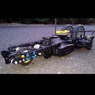
I completed the car again :) As i mentioned earlier, i compared the rc-unit vs PF-battery-box (+9v switch+micromotor+wires). The rc-unit is 100g heavier then the PF-box. This, and the fact, that i testet the PF-box under load... (at ~1000 rpm) running 2 minutes without activating the protection, resulted in using the PF-box again for my newest try. I changed a few things compared to my last car, but mostly things wich you cannot really see. Especially the axle-bearing and the reinforced rear-part of the car. At the same time, i was able to make more room for the wheels, wich results in a 1stud broader rear-axle, for more driving-stability The frontwheel is now also a 94.2 motorcycle wheel. At the end i ended with a really heavy 1150g . But i think the reworked rear-part and the new wheel could still bring some improvement. What i like most is the really soft "suspension" this time. I would say ~70-80% of the cars weight is sprung-suspendet now, as you can see in the video below: If evrything goes fine, i will do some testdriving later this evening. -
[MOC] Three Axle Truck
TechnicSummse replied to damjan97PL's topic in LEGO Technic, Mindstorms, Model Team and Scale Modeling
I don't really like the color scheme, but the truck is really nice :)