Bzroom
-
Posts
236 -
Joined
-
Last visited
Content Type
Profiles
Forums
Gallery
Everything posted by Bzroom
-
 It sounds like it's very much still in RND. Why create a new thread?
 -
Awesome mechanism. Great job.
-
Linear Actuator Gearbox
Bzroom replied to anton1678's topic in LEGO Technic, Mindstorms, Model Team and Scale Modeling
There's a piece for that :) http://i61.tinypic.com/2d0n9ci.jpg -
Sounds good. Personally I think you'll be fine with the regular TSOP receiver. I'm pretty sure the IR transmission quality comes from the transmitter. But I could be wrong. Also, the amplifier might be optional. Most sounds chips come with some onboard amp, as a "system on a chip". But overall it looks like you have the gist of things. I would get a headed aka proto board version of an arduino, with all the interfaces for development. When you really want to stick this thing in youre lego, you'll like assembly a single board with all the components, micro, audio, aux components, and then program it with a probe. So basically, dont waste your money trying to get something to achieve something it wont. Get a dev board, dev the system, and then make a release build that will fit all your polish needs.
-
Amazing.
-
https://www.google.c...playback module This looks like a nice one: https://www.sparkfun.com/products/11125
-
Separate your needs. Inputs: IR: Steering: ch1 blue Drive: ch1 red Daylight control: ch2 blue (momentarily in + direction to toggle on/off) Headlight control: ch2 blue (momentarily in - direction to toggle on/off) etc etc. You only have so many channels for IR. Outputs: Digital: 0: Running lights 1: Head lights 2: Reverse lights 3: Left turn signal 4: Right turn signal etc. Serial: 0: Audio board bus - The Audio board has prerecorded sounds that are triggerable via a one-wire command from the arduino such as "play: honk.wav" The hardware will run you $50 off the shelf if you're efficient.
-
Its entirely possible with an arduino. If you're going to go the microprocessor route then i definitely recommend the arduino platform. It will greatly simplify your wiring of complex components. You'll wire the Leds up to a transistor (look into darlington-array for a compact form), the transistors will be driven by the microprocessor, one per channel of control. PWM is pulse width modulation. It basically means if you blink an light source at a varying rate you can vary the perceived intensity. A higher pulse width and the light source will be brighter. This allows a digital processor, which only has on-off, to control a variable light source. You'll also be able to pick up an IR receiver, connect it to a digital input on the microprocessor, and through code you will be able to read LEGO IR signals from the air. You wouldn't need to hack u any power functions wires to tap into any extra receivers. The processor can be the receiver and the driver.
-
Effe's MOC Corner
Bzroom replied to efferman's topic in LEGO Technic, Mindstorms, Model Team and Scale Modeling
Sounds like a perfect opportunity for a custom part! http://1.bp.blogspot.com/-0RpcpIHel9A/Uf27r4oy9-I/AAAAAAAAJ2U/Juhwd9IpR6U/s1600/1972-vw-bus-T2-tire.jpg -
Effe's MOC Corner
Bzroom replied to efferman's topic in LEGO Technic, Mindstorms, Model Team and Scale Modeling
Good to know! Sorry, I meant the tires, not the wheels. The tires look like they are all terrain. This thing is so smooth, it needs some smooth tires.. -
Effe's MOC Corner
Bzroom replied to efferman's topic in LEGO Technic, Mindstorms, Model Team and Scale Modeling
You guys call this a "test fart"? Looks awesome. Love the fake engine. Dislike the wheels though. -
Linear Actuator Gearbox
Bzroom replied to anton1678's topic in LEGO Technic, Mindstorms, Model Team and Scale Modeling
This is a very cool design. Take note of erelender's drawing, see how all the axles go through each beam? The main point is that on both sides there is a beam that collect all the axles that will be under torque. This will keep them from separating and grinding. This is referred to as "double shear bearing." If you replace the part of your model mentioned, with the grey #2 connector and black "axle/bush," with a longer beam, you will be able to support much higher torque. Double sheer is very important if you dont want stuff to fall apart. Also generally in construction, sheer force is the most preferable, rather than bending force. The closer you can keep the beams to the gears, the more efficiently the grinding force will be fought by the beams. Regarding space saving: This is a very cool stand alone model. When you look at potential applications for this transmission, and you know which directions you really need the outputs to go, it will be possible to change directions in much smaller space, and maybe even send coaxial drive shafts to a given location. -
You could easily imagine a mechanism with one power supply and infinite number of switched outputs, the question just becomes the output selection. It's fairly trivial to think of a machine that could take up an indefinite size and produce an indefinite number of outputs with an indefinite number of time to switch them. But when you start to talk about real numbers the relationship between the number of outputs and time to switch between them is probably the most significant factor. Your described a model of 1 / infinity, which approaches zero. In the simplest mechanism, you have N inputs and N outputs, the ratio is 1/1. What would really be cool is if you could create a factor larger than 1/1. I think differential implementations of a polynomial functions would allow you to control more outputs than inputs. Think of a speaker playing multiple frequencies of sound through a single wire. The bass channel would be boom lift, low-mid and high-mid are left and right tracks, and a high pitch is a scoop. God speed.
-
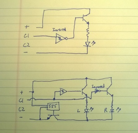
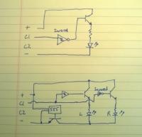
Yes. It should be about that simple. I left out some details about transistors. I've attached a high level schematic. Major components: 555 timer circuit (there are some auxiliary components it needs) Schmidt trigger: Turns an analog source into a hard step, needs to be biased for input and output range. Inverse Schmidt trigger: same as Schmidt trigger but step output is reversed. LED driver transistors: Some small signal transitions capable of switching the LEDs You'll likely want to find some multi-channel ICs for your triggers and transistors. There may also be some "system on a chip" blinker circuits to make the 555 building easier. edit: At second glance it looks like I may have massively over complicated things. At least for the reverse light, you could simply connect the LED across c1-c2, it will only light up one direction. For the turn signals, it might be possible to wire c1 and c2 into the top transistors safely without triggers.
-
In some cases you can have 4 functions at a time, but in most cases you will not be able to have that many functions at a time. Consider if the 4 functions you wanted to power were all connected to the same motor. They are not independently controllable. There are for more of these collisions than there are possibilities. I would say that average case, your mechanism will deliver one function at a time.
-
Technic-ly, neither are Power Functions: http://powerfunctions.lego.com/en-us/default.aspx
-
Or unless you use THIScontroller. Also i'm pretty sure the mindstorms can assign a position and have the servo hold it. I did not expect you to succumb to such a small limitation! A motor without return to center will drift over time and will not be suited for automated control and will make manual control more difficult.
-
You could use a microprocessor, or you could do it old school. You'll want some extra power functions wires you can cut up, that way you can piggy back off the receiver outputs. Then you'll be looking at two voltage lines, one for drive, one for steering, you'll use 3 triggers, Left (-steer), Right(+steer), and Reverse (-drive). Put a 555 blinker circuit on the common leg of the turn signals. That should do it!
-
Use servos to achieve the middle position on the clutch gears. Unfortunately you will only get 1 channel of independent motion from these 8 motors. If you had used the 8 motors independently, you would have 8 channels of independent motion. :) If you could synchronize all these motors with some mindstorms you may be able to use a fast enough refresh rate to make it seem like all the axes are moving independently, but really moving one at a time at an interval. This is obviously vary analogous to an LED matrix. The same techniques will apply for independent control. I was thinking about a similar system, I had planned to use double the number of clutches and inverse shifters to latch the channels when they weren't being addressed.
-
You have all the best. A dream!
-
[MINI] Offroad Racer
Bzroom replied to anton1678's topic in LEGO Technic, Mindstorms, Model Team and Scale Modeling
Trying to recreate the same body style as your mindstorms offroader would probably be a good start. You might sketch some ideas on paper and think through what you would need to build them. Thinking ahead will allow you to build what you want in less than 200 pieces -
Mindstorms Offroader
Bzroom replied to anton1678's topic in LEGO Technic, Mindstorms, Model Team and Scale Modeling
You have a very free-form style. I like it! -
Probably, imagine someone who couldn't afford any LEGOs, they would be at an extreme disadvantage in this competition. Unfortunately with most competitions, there is some cost involved with entry.
-
Little Dump Truck
Bzroom replied to Appie's topic in LEGO Technic, Mindstorms, Model Team and Scale Modeling
First studless moc!? Amazing. My mini entry is my 3rd studless moc and it's no where near this cool! -
Flight using Lego
Bzroom replied to anton1678's topic in LEGO Technic, Mindstorms, Model Team and Scale Modeling