
gyenesvi
-
Posts
2,396 -
Joined
-
Last visited
Content Type
Profiles
Forums
Gallery
Everything posted by gyenesvi
-
 Thanks, this was my actual guess. Furthermore, I believe there's nothing to prevent the rear axle from falling downwards when lifted for example, but I guess that also helps with the articulation.
 -
That's a nicely built core :) I am trying to make out the shock absorbers on your photos, but can't really see them, but I am guessing you are not using springs but 1x2 rubber pieces? Sure that's a more space efficient one, though I never tried to use them, not sure how I would start out with them, where to connect them to a live axle.
-
Really interesting build, it has some interesting solutions and asymmetries in it. It seems we have converged on similar techniques for framing the gearing part. Well I mentioned I'm working on it :) But certainly I can learn from yours! So to answer your challenge, I quickly made some renders of my latest version, which I have also built in real life. (I have a thread about my smaller scale off-roader builds, I am going to add this into that thread later, along with the chassis it fits into.) It is the same width, but the 'wheel hub' part is slightly larger on mine, not sure if the small tractor wheels would fit on it (I don't have them), it was designed for Arocs wheels. My goal was to go as slim and light-weight as possible with this. The backbone of it is an 11L flip-flop beam, without which it would probably not be possible, or would become much thicker. The steering system is quite different on the two, mine is designed for linkage based steering, instead of a rack and pinion. One point of improvement over yours I think is the steering geometry. It seems to me that yours has anti-Ackermann geometry (because the rack is in front of the axle), which is actually somewhat worse than no Ackermann geometry (plain old parallel). Another difference is that I designed mine with two lower links and a panhard rod instead of four links (but I believe it could be made with two upper links as well instead of the panhard rod), since the springs are also giving it stability against tilting forwards/backwards. By the way, I wonder where you mount the springs on yours? An interesting thing I did with the real life version is that I managed to put Efferman's 3d printed 2-wide 20T differential instead of the fixed gearing. It also requires his custom 12T gear mounted on a 2L axle to drive it (2.5L altogether), driven by a U-joint from the other side (that's why I have the axle that sticks out in the middle prepared for that in my render). I believe the same diff could be used in your version as well. Interestingly, that differential only works with these CV-joints in the wheel hubs, because the left/right sides of the axle have to go into the 2L diff all the way to the center, creating a half stud offset, but because this joint has a 1.5 stud hole in it, it can nicely accommodate that.
-
Really nice truck, I love the modularity, and the stock version looks cleaner to me than with all kinds of extras, but that's just my preference I guess. Maybe if some extras would be of different color, like DBG, to visually separate them from the core body. Nice build on the front axle; I am also struggling with the same decisions, working on some small live axle build. I love the trick you used to add support for the drive axle in the middle point, that works really nice without a differential. For now, I go with the CV joint solution, limiting the steering angle, I'll see how it is. That's exactly what I have been thinking too. It would be very useful for these kind of builds, and also could work in a more tightly designed new portal hub (I think it's time for a new one). Plus it could be used as an incoming joint into a live axle, with pivot closer to the axle, leaving more space in the middle of the chassis for the drivetrain.
-
[MOC] KamAZ-4310
gyenesvi replied to LegoV94's topic in LEGO Technic, Mindstorms, Model Team and Scale Modeling
Looks fantastic, but mechanically it is a bit overcrowded for me (I guess it is probably because of the scale). For example, in the front axle, the differential and the CV joints seem to be just loosely sandwiched in between the two frames, without actual support through axle holes, right? The driveshaft and the steering shaft also seems to be complex for what it does, for example the steering contains a bunch of small gears and joints, probably causing significant lag and loosing the precision of servo control (though still better than on-off control). And by the time the drive reaches the front axle from the motor, it goes through 6 U-joints if I see it right, which could be somewhat fragile (though that one L motor won't break anything). Nonetheless, I bet it works for your purpose, interesting solutions! -
Auto stop motors?
gyenesvi replied to jelockwood's topic in LEGO Technic, Mindstorms, Model Team and Scale Modeling
Isn't that itself just a more complicated implementation of what a white 24T clutch gear goes? :) Though the clutch resistance may be different. -
Auto stop motors?
gyenesvi replied to jelockwood's topic in LEGO Technic, Mindstorms, Model Team and Scale Modeling
Thanks for all the exhaustive answers, great that you tested all these already! By any chance, have you tried programming it the way it works in the Liebherr's main controls, where if you move the slider out of the zero position it starts moving in that direction with speed proportional to the distance from the zero position, and stops automatically at the two ends? So that would be different from moving to the position dictated by the slider position. It would be cool if that could also be programmed! Sure, as long as the strings can withstand the force of the motors during calibration :) That's looks like a fairly compact mechanical solution, if I understand correctly it would work in both directions due to the symmetry of the orange catch, right? But what conditions are needed to actually make it work in a real application? Without a rubber band on the orange selector, it would probably engage and turn itself off under smaller load as well (i.e. the weight of the elevator). So if I understand correctly, you'd need a rubber band that is strong enough not to let it engage under the weight of the elevator, but not too strong to let it engage when the elevator is actually blocked, right? -
Auto stop motors?
gyenesvi replied to jelockwood's topic in LEGO Technic, Mindstorms, Model Team and Scale Modeling
Hmm, how would that work in practise? What would the calibration sequence do to arrive to the conclusion that the zero position is the bottom position of the elevator? Move the elevator up and down between the two extremes? Would that require the elevator to be built with a physical stop at the bottom/top? Would it also calibrate the other end, i.e. calculate the range as well? I guess if the elevator is held on a string then physical end stops would not be feasible. -
Auto stop motors?
gyenesvi replied to jelockwood's topic in LEGO Technic, Mindstorms, Model Team and Scale Modeling
If I understand correctly, this would move the elevator to any position dictated by the slider, and the range (end position) could be set with the multiplier number (the other end being 0). This could actually be an interesting solution. One remaining question though is calibration, i.e. what is the zero position. I believe that will be the position the motor is in when the app starts, right? So if the elevator stopped in the middle, and the app is restarted, the middle becomes the zero position after restart, which is not ideal.. Is that any solution you know of for that problem? -
Interesting phenomenon, but I still don't quite understand why it works better with a massive up-and-down gearing. It sounds a bit counterintuitive. I mean this model has down-gearing in the portal hubs in the end, but it is still not smooth. I agree that's a problem, I'd even welcome shorter connectors with ball socket to make that hub more usable..
-
That sounds really good, although I thought that the bevel version was already quite good there. Curious to try this once I get my hands on those gears!
-
Auto stop motors?
gyenesvi replied to jelockwood's topic in LEGO Technic, Mindstorms, Model Team and Scale Modeling
That's a solution for a very simple scenario, but it all depends on how sophisticated it needs to be. With this program you could only start it from one end, and it would go all the way to the other end. You could not for example move it by a manual controller, like the Liebherr, and avoid going over the ends. Also, if you want to stop it in the middle and restart moving, this would need to get more complex. For these scenarios, you'd need some kind of a variable to store the actual position and cap that with the end positions, and I am not sure if/how that's possible. Also I suspect that this system does not need actual remote control, it would be just a button/switch on the model itself I guess. So even if one would use the simple 2-switch PU hub from the Osprey, that's not possible to program, as there is no app involved in there, right? So it essentially functions like a PF system would.. -
That's an interesting question, don't know, the Mindstorms app's programming interface seemed much more well designed. Wonder if it's possible to program simple servo steering, or a gearbox though. Have you tried something like that? The PU app has some predefined blocks, for example for servo steering. Also, I have read somewhere that the Mindstorms app may have some lag when used for remote control, because the whole system was mainly designed for programs running on the hub itself, not for fast communication (though I don't remember if this was in relation to a physical remote controller, or for phone control as well).
-
That's my problem, I don't remember, and can't find it again, it just came up during some unrelated search :) But thanks for the links, now that I went through your models in there, it may have been this MackMagma. However, I think I mistook the large turntables for small ones, and the suspension works differently than I thought. I remember seeing those red triangular links connected by the long beams that move back and forth as the axles tilts (that part is similar to mine), but in your model, they are connected to the axles through vertical 6L links, not by gearing from the turntable. Now it's clear how yours work, so it's different from mine, but in the end it did help me understand your technique, thanks! I like that massive up-gearing, that's interesting in combination with planetary hubs. Yes, I also tried to use more connectors and less long axles that could twist, because my main driveshaft is pretty long. And one other thing I did to minimize twisting is that the driveshaft gets drive in two places closer to the axles instead of just in the middle. That would have been my other guess, that those newer diffs in the Zetros may be more solid in transmitting the drive than the regular ones that are in this set. Maybe it's just all of these factors added together that result in a less solid drivetrain in case of this older set. No problem, I like when there's more technical discussion.
-
While I believe that the hardware is fully compatible, I think the bottleneck is the software (which is sad). I bought the Mindstorms set with big hopes for that hub (and also for the motors and other sensors), but when I tried (a while ago) I was disappointed that Mindstorms hub was not supported by the Powered Up app. I learned that they use different Bluetooth technology: the Technic Hub uses Bluetooth Low Energy, while the Mindstorms hub uses Classic Bluetooth, so they require quite different software to connect. I am not sure if there was any progress in merging them (or if ever will be). I have only seen one technic MOC with the Mindstorms hub running with PU motors, but that was also controlled with the Mindstroms app (I guess for the same reason). But it may be worth giving the Mindstorms app another try (at the time my phone was not able to run it), and also as far as I remember it should be possible to connect a physical controller to it. I'd be interested if anybody has experience with that!
-
General Part Discussion
gyenesvi replied to Polo-Freak's topic in LEGO Technic, Mindstorms, Model Team and Scale Modeling
Oh that's really good to have in DBG! Thanks, I wouldn't have thought that either. The trans clear stuff could be useful actually to build some invisible support structure. -
General Part Discussion
gyenesvi replied to Polo-Freak's topic in LEGO Technic, Mindstorms, Model Team and Scale Modeling
Just wait a bit and they will appear inside some model in the name of color vomit coding :) Wow, I'm seriously baffled by the existence of these, I didn't know about them; do basic liftarms also exist in these colors? I mean I get that in those sets they look nicer if they appear in the right color, so be it, what I don't get is how on earth at the same time technic models don't deserve to get some pretty basic parts like connectors in simple colors like black / red / yellow! (that could be reused in many sets, unlike these ones I guess; or do they appear in many sets of that theme?) -
Thanks guys, glad you like it! Nice that you spotted that :) The crankshaft part seemed like a neat solution to make that half stud offset, but I had the same worries, and started testing it moving it back and forth 50 times, and of course slowly it would detach itself. But then I stumbled upon this simple fix with the 1x2 brick, which fits into the tight space and it holds it surprisingly well, it never came off during driving. I also learned it from others' builds :) And works better than I expected! Actually I only saw some photos of your model somewhere and suspect that it has a similar suspension technique, but could not find details about it. Do you have some description of that model somewhere? I'd be curious how similarly we implemented the same concept. Thanks, glad you see this as a continuation of the Jeep. And yes, a better camera can make a difference for the photos, and also the videos :) I think I get what you mean about the continuity of the output, I noticed this too and wanted to ask you guys whether this is a feature of the PF system. I noticed in other people's videos and with this model too, that it feels like the output is not completely continuous but a bit periodic. This is something I never experienced with the PU motors, those seem to have quite stable continuous output (though I always used them with planetary hubs). First I thought it might be because of the gearbox or the usage of U-joints in the front axle (instead of CV joints), but it also happens when it's running straight, which should not be effected by the U-joints. Furthermore it's still noticeable when I remove the gearbox and simplify it to fixed gearing. So is this something others have also experienced with PF motors? Or is it specific to the XL? When I motorized the Creator Mustang with 2 M motors, I did not notice such a thing, neither when I built Madoca's lightning buggy with 2 L motors (although I was running them from a BuWizz, not sure if that could make a difference).
-
@Phondly was kind enough to provide me a prototype piece of his battery pack for the PU Technic Hub, so I have created a short video summarizing my impressions during usage with one of my off-road models:
-
I like the massive suspension on this one, and the in-axle motors, I want to try that once, though it needs a lot of space. Though I wonder whether it really needs to be raised that much, the real car seems to sit much lower. I mean I get that you want to maximize suspension travel, but does it actually use all that much? The bodywork is also a good start, I like the tubular/panel mix, but maybe missing some bits in the front?
-
Unexpected alternate, it's a really nice match for the tires and the color scheme of the set, I guess that's how you chose it? I like how this is on a very different scale than the A model, and nice that you built a custom engine.
-
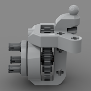
Hi Eurobrickers! I'd like to share with you a build that took me quite a long time to finish. Around the beginning of last summer, when the Zetros was rumored, I started thinking of building a trial truck, or some other capable off-roader out of 42070. As it is codenamed All Terrain Tow Truck, I wondered if it is possible to build something out of it that actually performs reasonably well off-road. The biggest obstacle obviously seemed to be the lack of proper suspension parts, so I started experimenting with a suspension concept inspired by the Rocky alternate of @Didumos69; linked pendular suspension where the body tilt angle is the average of the axle tilt angles. However, the implementation of the concept had to be different from Rocky, where the averaging is achieved by gearing together the two large turntables. In Rocky, the two turntables are relatively close to each other, and the PU hub makes up the center of the chassis, with the drive motors placed in the two axles. However, set 42070 has only a single drive motor, so a drivetrain must connect the two axles, so it seemed straightforward that the motor and the drivetrain would be in the center, which would have been in the way for any geared linkage between the two axles. Also, the distance between the turntables used to mount the axles is much bigger, and at this distance, if the front and rear axles were connected through gearing, the thin lego axles connecting the front and rear axles would twist so much that the linkage would be ineffective (gooey). So I decided to mesh gears to the turntables sideways, which transmits the rotation to the horizontal direction, and that way the two axles can be connected by a long link built from liftarms, which is solid enough. This method also leaves room for the drivetrain in the middle. I had to fiddle some time though to frame this in a solid way. I must note here, that I recently discovered a build of @Thirdwigg that seems to use a similar implementation, though I only found some photos of it. After building a proof of concept for this part, I started building the axles themselves. The rear axle was simple, but the front proved to be hard given the parts and my requirements. The difficulty was the steering. The set has an M motor for steering, so it has to be geared down significantly to be useful, and some clutch mechanism must also be added for protection. I tried both on and off axle motor placement. The off-axle version required a ton of gears to route the drive to the steering coming in from the front of the axle through a small turntable, it ended up awfully complex. So I opted for on-axle motor, but that resulted in really small space (I did not want to build a large front axle, because that would have caused problems with the room for articulation, would have required a lot of space around the axle in the front). I tried both with a clutch gear/worm gear combo and a small linear actuator based mechanism but could not get it to fit and work properly. After giving it a few more tries, I set the project aside for a while. (In the meantime, the Technic contest of 2021 came, and I used the same suspension concept in my small scale 6-wheeled moon buggy). Recently I started fiddling again with the steering concept, and finally was able to make a compact front axle using small linear actuator based steering. Though I had to give up one detail of perfect geometry: as the tie rod moves to the sides, it also moves backwards towards the axle center, and the linear actuator cannot pivot in that direction, so it can only follow that movement with a slight bending (the axle that it's driven by, and the actuator piston itself), but I think it's within the tolerance of lego parts, and I have seen this technique used in other MOCs as well (I don't really think there would be a good way to avoid it, since there's no chance of flipping the actuator by 90 degrees due to the tie rod being right under it, no matter how I build it). Apart from this detail, the other difficulty was mounting the M motor in a solid way, but I think that part came out fine. Furthermore, I had to attach the end of the actuator on a half stud offset to make use of its full range of 3 studs movement (1.5 studs in each direction), resulting in quite good max steering angle (also supported by the U-joints going into the portal hubs, as opposed to CV joints for other types of hubs). Here is the whole axle: So after solving this bit, the project got new momentum and I started working on completion of the model. I built a rolling chassis, made a test drive on some rocks and it performed surprisingly well, so I started to work on a gearbox and bodywork. For the gearbox, I thought I'd use a 24T differential available in the set to make a 3x gear ratio, keeping the same ratio as the A model for high gear, and 3x slower for low gear to support climbing. However, I encountered an interesting failed scenario here. The differential is easiest to use in a setup that results in a 3x speed-up (rather than a down-gearing, and the same would be true for a 24T clutch gear if existed), because as the drivetrain goes from the motor higher up in the chassis downwards to the driveshaft, the gear stick is easiest and most natural to place above the clutch gears (including the differential with its 24T gear), so the drivetrain below has to receive the drive through the 8T gear, resulting in up-gearing. So in order to have down-gearing in the system, I had to place some down-gearing before the gearbox, which is cancelled by the up-gearing on one path, resulting in 1:1 ratio, and not cancelled in the other path, resulting in a 1:3 ratio (another option could have been raising the whole gearbox and placing a down-gearing below it, but I don't like that scenario as there would be a big gear sticking out at the bottom). Easier shown than described: However, while this looks good on paper, it failed in an interesting way. In low gear it worked quite okay, without significant clicking around the clutch gear, but in high gear it started to click as soon as the model was not going straight on a flat surface, but something more demanding, even while turning :) I figured that the problem was that the gearbox in this setup is under high torque, so less stress is enough to make it crack. I had to redesign the whole thing where there is no down-up gearing in the system. (I also have to mention that the clutch piece can go less deep into the differential than into the 16T gear, and that may have also contributed to the fact that that route clicks more easily). So the other way to use the differential as a clutch gear would be to drive it with an 8T gear from the top, resulting in a down-gearing, but that presents a fundamental problem: where to put the gear stick, as it's just in the way for an axle above the gearbox (alternately, the clutch gears could be driven from the side as well, or the switch could also be sideways, but the model does not have space side-ways because of the suspension linkage running exactly there). So I thought about an unorthodox solution: could the gear stick piece be moved one stud to the side, out of the way of the drive axle? At first I thought that would be weak and disengage too easily, but luckily the set has enough of those pieces, so I could try two of them, one on both sides. So I did, and it works in a surprisingly solid way (if the tilt of the stick itself is limited)! Here is the final gearbox design, in which only the gearbox itself performs down-gearing on one path, and the clutch gears are not under so high torque, so it does not click under normal usage (of course, it can be pushed so hard that it becomes the weak spot of the drivetrain, but that's inevitable). And here are all the functions color coded (red is the suspension itself): As for the shape and bodywork, first I thought I'd build some kind of a truck, for example a trial Unimog (that would have been a good match for the portal axles). However, the available azure parts were not so good for the shape, there are mainly large flat pieces and few triangular ones, so I quickly moved on to another idea. For a while I have been admiring Flatgekko RC crawlers (check out some awesome videos on YouTube), so I thought I'd try building something in that style. It gave me an interesting idea to test: putting the center of gravity into the front of the model. The motors have already been well placed for that, so I thought I'd try placing the battery above the front axle. By the way, that's also the lowest point where I could place it; as said above, I could not place it low in the middle as Rocky does, since the drivetrain and suspension linkage would be in the way (and I definitely wanted to avoid placing it high at the back). Although this hub is hard to use as a structural element, placing it right above the front axle was easier than I first thought. Here is the complete chassis, including a roll-bar to hold the roof, and the IR receiver in the back of the cab. The long rounded panels available in dark azure were good to build a Dodge Power Wagon style cab roof and nose, and the few wing-shaped panels were okay to make the sides. I finished the back with a tail bed, that can hold a spare wheel fixed by chains. Here are some renders of the finished model. And some photos in its natural habitat :) More images are available on my Bricksafe, and building instructions are available on Rebrickable. Finally, I want to note that this has only been my second build with the PF system :) and I was pleasantly surprised here and there in comparison with PU. First, the PF XL motor is just so powerful in comparison to the PU version. I don't know if the actual motor itself is that different, I know the gearing is, but I also suspect that the PF one is not limited by control software, and that can matter a lot. I was surprised that a single motor can move such a big model so powerfully. If I push it really hard upwards, it can seriously bend some axles and break some gears (or at least crack them), but it definitely won't stall.. The other thing that I really liked is the physical remote (I built a steering mechanism onto it). It makes such a difference wrt the phone control of PU, it was much more fun to play, and much easier to film and control the model at the same time. A steering system with the M motor and the linear actuator is an interesting technique, and while it works better than I expected, it is still more cumbersome to drive around and somewhat weaker than a PU servo based solution (the clutch inside the LA may click if the wheels are blocked hard), so I have to give that to the PU system. Let me know how you like the model! Cheers, Viktor
-
Auto stop motors?
gyenesvi replied to jelockwood's topic in LEGO Technic, Mindstorms, Model Team and Scale Modeling
I would definitely do this with PU instead of PF, that's exactly what it was designed for due to the position sensors in the motors. For example the controls in the Liebherr do this exactly, and you don't even need to turn it back on when you want to reverse. I haven't ever tried programming that in the PU app though, wonder if it's possible.. Or are you after the fun and complexities of solving it all mechanically? -
[MOC] Lego Jeep Cherokee
gyenesvi replied to filsawgood's topic in LEGO Technic, Mindstorms, Model Team and Scale Modeling
Although I'm not a big fan of the real car (the idea of a Jeep SUV itself), I like the build, it captures the shape well. Good to see a model at this medium scale, and that you incorporated planetary hubs into it. I like the diff locking, and the front axle build also seems interesting. Is the steering motor sitting on the axle itself? -
Interesting test, thanks for doing it, I'd also suggest trying it the other way round with the gearing (up-gearing) to see how that effects the results!