
gyenesvi
-
Posts
2,396 -
Joined
-
Last visited
Content Type
Profiles
Forums
Gallery
Everything posted by gyenesvi
-
General Part Discussion
gyenesvi replied to Polo-Freak's topic in LEGO Technic, Mindstorms, Model Team and Scale Modeling
I'd love to see such a system work, it would immensely help in building live axle links (and would also be useful elsewhere). I am actually building something now that could really use these, where I need long links like 13-14L. I wonder if they could be made without the need for the latch, just with the axle end clicking into ball socket part in a way that it would not be possible to pull out only with a lot of force or a bit of help to release it (like it would need a tool to lift a little tooth or something). And yes, the axles should be the same color.. which is unlikely to happen.. That's exactly what I have come up with too! Or alternately, this part would also be useful with a towball socket instead of the pinhole for the same purpose. -
Hmm, surly there's some slight trickery compared to an ordinary technic door hinge, since I don't see the hinge from the outside, the vertical axis or rotation does not seem to be on the outside surface of the door on the video when you open it. And now that I looked more closely I can see why you use some plates in stead of another 5L beam right in front of the door: to make a tiny gap for the opening; that's a nice one. But still don't get where the hinge axis is.
-
Exactly this, I had some similar failed builds, and also some needing a 7L link. It's kind of a shame why such a useful part is not produced in more lengths. Even the existing 9L is not so usable as the 6L because it is not double sided (it would be timely to update that mould to make it double sided). About the heli, the mechanism itself is looking quite interesting, it's great how much can be done with the right parts, curious about the reviews.
-
I've seen this one coming up on FB and was totally amazed (even though I am not much of a supercar fan). The bodywork is the best one I have ever seen for a technic car, it mixes technic and studded elements very nicely, I especially like the way the doors are built, it gives it such a clean look (though the stickers also help a bit :) ), and the way the fenders are integrated is so seamless. But then there's the internals, the electronics placement is genius, the way the various drivetrains pass by the motors, and the way the whole thing gives it a nice backbone. And on top of that the battery is also quite well hidden. Great work on that! The drive footage is also cool, it has quite good steering radius too. I wonder how you built the door such that it opens without the parts blocking each other. Is there some trick in the hinge mechanism (besides the springs)?
-
That's a well made alternate with cool functions and nice details (love the way the machine guns pop up), I was actually expecting this to come sooner or later :) Finally an alternate model frontpaged :)
-
42136 Alternative model
gyenesvi replied to damjan97PL's topic in LEGO Technic, Mindstorms, Model Team and Scale Modeling
This is really nicely built with those limited amount of parts! I especially like the shaping of the front. -
Nico71's Creations
gyenesvi replied to nico71's topic in LEGO Technic, Mindstorms, Model Team and Scale Modeling
I like this format, it's great to see the steps and failures of the design process, the reasons why you chose this or that technique. Nice chassis you have there so far! -
Pybricks Q&A
gyenesvi replied to Pybricks's topic in LEGO Technic, Mindstorms, Model Team and Scale Modeling
I'd say if you have a physical limiter, and you can only shift up/down with two buttons as you described, then the problem does not exist, because you won't be even able to try to go from 4th to 1st (unless you explicitly program it in a way that incrementing 4 becomes 1). So given that, you'll have to go through 3rd and 2nd to get to 1st. On the other hand, if you want to go from 4th to 1st, then you probably built it without a limiter :) so the problem does not exist again. I guess it's best if the software logic matches the built hardware, then things become simple, and no need for heuristics. So this trick would only be required if you have a build with limiters that you cannot / don't want to change and have buttons that allow changing directly to any gear. -
Pybricks Q&A
gyenesvi replied to Pybricks's topic in LEGO Technic, Mindstorms, Model Team and Scale Modeling
The above approach can work (note that the same thing could be achieved by simply taking the integer part of the division, that's what trunc does I believe: int(angle/90)*90, and then you don't need imports). However, I would use a completely different approach for gear shifting. In your approach, you are reading the motor position and doing +/- 90 degree shifts, which works in theory, but in reality it could have errors which accumulate after successive shifts. Instead, you could just tell the motor where to move exactly, because you know that. At least you could know that if you know what gear you are in, and where you want to shift. And that would also solve your other problem at the same time. So the key is you should maintain a program variable for your current gear, that would run from 1 to 4. Then you know that if you press the right button, you want to increase the gear, and if you press the left button, you want to decrease the gear (simply increment / decrement the variable). You can also add logic that you can not shift up from 4 or down from 1. You can initialize this variable to 1 for example. After that, you can easily calculate the angle you need to aim for: angle = (gear - 1) * 90. And then with a different command that should exist in Pybricks, you need to send the motor to the given absolute position given by angle. That way errors don't accumulate, no need for reading back the motor position, and you have the info to display the current gear too. Note that at startup, you should send the motor to angle 0 to be in sync with the initialized first gear, no matter where it was left off the previous time. Hope this helps! -
Thanks, that's exactly the layout I had in mind (if I am not mistaken, the fork pieces are now on the underside). I guess that's as compact as a 4-speed gearbox can ever get, and it seems solid enough! It would be amazing to test this with injection moulded parts. I wish TLG sometimes made a system based on fans' ideas, this could be a great candidate :) Great work!
-
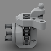
Thanks for the detailed video, now I think I understand the whole system. And I have to say those pieces seem already nicely designed, hats off man! Some details are really required to make this work in a tight space, for example I like that the clutch gears have their clutch teeth on the outside, this way it can work for small gears as well. Also that the clutch gears sit on the 3L axle joiner instead of the bare axle, that probably also makes them run smoother. The fork piece is also a really interesting one, I can imagine that it could be sliding smoothly while firmly taking the driving ring with itself, though I am a bit afraid that this may be the weak spot of the system, as that adds an extra step of indirection to the mechanism compared to the Lego wave selector that directly slides the driving ring, and may have enough play that the clutch teeth could disengage under high torque, like in an RC build (though I understand that that indirection is required to make it work in a tight space). It would be great to know how much torque it can take without disengaging. Also, I like that all the important distances fit onto a regular grid. I wonder if the selector mechanism could be folded downwards to be next to the lower line of gears (it seems that the wave selectors would be right where there are no gears), so the whole thing would fit on a 5x5 module space when viewed from the front (currently it's about 7x5 modules if I am right, not counting that the 24T gear needs slightly more space).
-
It's really cool to see both the way it rides and the way it fires! Can you give more details about the loading / firing mechanism? I don't quite get what you are trying to show on the video when you are adjusting all those knobs, and the description does not answer that either..
-
This is strange because I believe it should work as you wish it worked. The Lego Wireless Protocol allows the motors to be run in speed servo mode, in which it automatically adjusts the power (~voltage) as much it needs to maintain the speed (up to an adjustable max power budget, which can typically be set to 100%). Now the question is whether in the robot inventor app when you run them at 5% speed it actually runs in speed servo mode, or in regular PWM mode just giving it 5% power. But I believe we can't answer that without understanding the code behind the Mindstorms app, which we will never know. Now first I'd definitely test it with properly recharged batteries. Second, maybe the 5% speed is too low for the whole speed control loop to work properly, especially for XL motors. I have noticed that it takes a bit more power to make them start moving than L motors for example. I have made some quick tests with my custom desktop app that uses the lego wireless protocol to query/control hubs/motors. As the 5% speed seemed too low for this, I used 20% speed. When I set the motor to simple power mode, it's definitely very easy to stop the wheel connected directly to a single XL motor (I used an Arocs wheel, but its size does make a difference here). However, when I put it to speed mode, it got noticeably harder to stop the wheel, though still quite possible, but I feel that it's working against my hand. This may be useful as a comparison basis for your experiments to guess how the Mindstorms app may be working. Also, note that the Mindstorms hub has ~7.2V batteries, while I'm testing with the Technic hub and 9V batteries.
-
I'm actually surprised that competitor companies (even one that are not simply cloning) use 99.9% the same parts as Lego, and rarely ever invent new ones, not even existing designs in new lengths for example. The only thing they do is some recolors compared to lego. AFAIK only Cada dared to invent a few new parts, but not many.
-
Wow, that's pretty great that you actually printed and built this so quickly and it works so well for the first try. I think you chose the right gear sizes, because this is the only sequence that can still be kept in a 2 module spacing, without getting too bulky because of too big gears (and then every part would have to become bigger and would probably be more wobbly and less precise). It would be awesome to see only a 4-speed version of this (maybe with 24T, 20T, 16T and 12T gears), but strongly braced, I'd be interested if an XL motor could make its gears skip (which probably also depends on the amount of down-gearig after the gearbox towards the wheels). Do you plan to make some field tests with a more complete chassis? I also wonder what other layouts would be possible for the whole assembly? Currently it's really tall (even not counting the frame), but would it be possible to move the shifting components lower but to the side for example?
-
Yes, indeed, that can happen because of the scrub radius, I did not test yet, will see soon. I have the same experience, if you add gears or joints (even the new ones), centering does not work well Again, agreed. But still, just for the technical part, the solution with the angular servo is interesting because it's not the good old one. I am planning to try Controlz. So far I only used the PU app, on which centering is just crap on my tablet, even the slider in the app cannot properly return to the center, only approximately.. Oh, I did not realize that, I never built the Arocs..
-
That's true that it becomes weaker, but I am not sure if that's an issue, because the large angular motor is very strong. Will be interesting to test, I will see if it's strong enough when I do more tests off-road. But the 2,5 arm is also a good idea, I thought about that too, but would need more modifications to make space for it while keeping the linkage geometry good.
-
So I found the time to build this and what a beast! It's huge, looks cool and rides really well. It's really powerful with the two PU motors (I am using it with a 9V Phondly battery prototype). I like the suspension, especially the front one is a nice compact design in the limited space (during building I thought first that the front axle won't have a suspension because of the limited space, so it was a nice surprise). The chassis structure is also solid, and I like how the bodywork is completely separate and detachable. I especially like the cab build and the doors, they are nicely shaped and open cleanly (love how the mirrors are kind of essential part of the structure). Also, the detachable rear section is really nice, when it's on, the dakar truck is huge, and when it's detached, the trial verision is a cool light-weight one. With the larger wheels, it's even more awesome! The only thing I was not satisfied with is the steering geometry, because it is asymmetric. This is because it uses the angular motor's circular rotating mount, which is essentially like a short 2L arm (servo horn), which when turned left pushes the steering rack slightly less than 1 stud, but when turned right it pulls the steering rack slightly more than 1 stud (because of the linkage mounted on the left of the tie rod). Because of this and the limiters on the tie rod at 1 stud distance, on the left it does not reach its limit, so it does not steer left so well as to the right. So I set out to try to improve it. The idea was to use a 3L servo horn. To achieve this, I flipped the motor upside down, moved it back one stud (it was easy to remove some structurally not important liftarms to make space for it), and used the 3L cam pieces available in the set as the servo horn instead of the circular mount on the motor itself. With the 3L servo horn, the motor does not have to turn 90 degrees, so its movement is more symmetric, and can reach its limit in both directions (also, the servo horn can be limited more naturally on the bottom). Furthermore, it gives a possibility to further increase the steering angle by removing some limiters from the tie rod. I was able to achieve 1,5 stud sideways movement of the tie rod, which results in about 45 degree steering angle, which the U-joits can still handle. Also, I have made some simple off-road tests, and even with the larger tires, the wheels don't get stuck in the chasiss or body (though they can get quite close). @rm8, if you are interested I can send you some images of my mod, I'd be curious what you think about it. I'll perform some more off-road tests later, from the preliminary tests in the garden it has good balance between speed and torque to go through some rocks :) The drivetrain's simplicity and low friction really pays off here!
-
Oh, okay, so you either spin the rotors or use the winch. Maybe it's safer for the hands :)
-
Do we know for sure how many motors it has? 1 or 2? The dumb battery box could control two, and one of them could be used for the rotors, the other for the rest of the functions through a gearbox. Is that how it was in the Osprey as well? I'm not so much into the looks, but I like the mechanisms, seems interesting.
-
Indeed, you are right about that. And maybe also Lego itself has some coolness factor nowadays, especially for decorative purposes. I think Lego Ideas sets also aim to ride that wave. I was seriously thinking about buying the typewriter just to put it on the shelf.. But we are already diverging from the topic of the thread..
-
I agree that this could be part of it. On top of that, I think it's easier for adults to justify buying and building with lego if it contains all those gears and internal mechanism. You know, it feels more adult-like to build complex things (even if one doesn't understand them) than just putting bricks on top of each other.. But as for you, this is just my interpretation. On the other hand, I build for the design challenge (be it technic or brick-build), which is a different experience, and mainly buy sets for the parts.
-
That's a great video, and I'vel learned two things. First, the gears should indeed be asymmetric to pack it into a small space (about half stud for the teeth, just like current gears, and about the other half for the engaging surface. That could even work for 8T/12T gears without the need for extenders (but also 10T, 14T, 18T gears could be used if they are speacial anyway). Second, the small teeth for the engagement mechanism should be triangular shaped pointing inwards, that way the force pulls the gear and selector together, instead of pushing them apart. Starting to believe it could work out. I also agree that the lengh of those selector parts should be minimized to avoid friction and jamming because of the necessary free play of the plastic parts. It would be good to keep gear sizes such that they work on a regular grid, 2 studs apart.
-
That's an interesting start, though I have wondered before if something like this is actually possible from plastic in a solid way. I think the problematic point may be size (depth) of the teeth on the driving ring that catch the otherwise free spinning gears. That's roughly 1/4th of a stud here, which may not be enough for a solid connection, given some (required) free play of lego parts. Even the almost half-stud tooth-size on current lego gears and driving ring can disengage under stress (though not with a rotary catch, but only using the old changeover catch in a manual gearbox). So it would be interesting to see if something like this can withstand forces, because the teeth cannot really be made bigger (unless the gear are made asymmetric?) without bloating the whole thing substantially with 2L / 3L driving rings). The rotary cams lock in 45 degree positions, right? That may also be more cumbersome to build than currently used 90 degrees. Though I'd even like this for only 4 gears, arranged in 90 degrees, and that could even be done with currently available gear sizes, though small ones would require extenders, adding length.. I suspect these may be the issues why something like this does not exist in lego.
-
Baja Truck
gyenesvi replied to Lox Lego's topic in LEGO Technic, Mindstorms, Model Team and Scale Modeling
Thanks for some more details. As for the off-road version, I wonder why you'd go with L motors. BuWizz motors are more powerful and faster, so they should perform better off-road too, and the essence of a trophy truck I think is high speed off-road. Can't see the drivetrain exactly, but I believe you are already using slower output, which could be made a bit slower if it needs more torque by using a new diff with 12:28 gearing. Also, maybe the gearing that couples the two motors could be 12:20 (as far as I can see right now it's 12:12?). As for testing, I'd definitely not go for grass, that's quite bad in my experience, lego models get stuck very easily, but rather some dirt or gravel road with small bumps. It would be great to see how the suspension using 4 of those new blue shocks performs there. Is it responsive or somewhat stiff with those? And again, I'm not against frontpaging cool looking stuff with stickers, but I also do remember people being called out for similar posts that only contain some images and no details, or being just copied from Rebrickable. I also sell instructions and don't want to give away all the details, but I always aim to share more tech info here on EB, especially about the mechanisms and the design process, since that's what can kickstart a more in-depth discussion, and I guess that's what many people enjoy here (and also if someone just wants to use some of my ideas for their own builds, I'm okay with them learning it without buying the instructions).