
gyenesvi
-
Posts
2,396 -
Joined
-
Last visited
Content Type
Profiles
Forums
Gallery
Everything posted by gyenesvi
-
General Part Discussion
gyenesvi replied to Polo-Freak's topic in LEGO Technic, Mindstorms, Model Team and Scale Modeling
That's interesting to know, thanks! -
General Part Discussion
gyenesvi replied to Polo-Freak's topic in LEGO Technic, Mindstorms, Model Team and Scale Modeling
Interesting, my 8880 has these in grey. It's the towball pins that are black in there. Are you sure it came from that set? Or maybe there were different version wrt packaging? Do you have the instruction booklet? In which color does it list those parts? I don't have access to mine right now, but I do have it somewhere.. -
Well that is indeed a genius solution (love the steering as well)! Thanks for showing! However, it does not really fit my idea of clean and solid, neither is it long travel, and it does not have a diff either :) But for a small model like this, it's really nice.
-
I agree with you for the case of fast vehicles (I guess that is why buggies like Ultra4s and UTVs have them), but I think for a slow trial truck the front live axle setup can be better because of the more ground clearance it provides. Also, another thing to consider is that IFS is only really useful if it is high travel, but that's something hard to achieve in lego on a smaller scale or in a narrow vehicle (like a truck) when it is driven, because the diff already forces the A-arms to be far apart and shorter (unless you drive left-right wheels independently, which complicates the drivetrain). So in some sense the live axle is even simpler to build. For medium scales, like 13 wide axles, a (clean and solid) driven IFS is just impossible (maybe with a floating diff), we are only left with live axles as a possibility.
-
I'll be honest here since I also plan to try and make an RC version of this model; anything that is not 4WD (or does not keep the live axle suspension) does not cut it for me. It is pointless for me to do a non 4WD motorization for this car as 4WD and live axle suspension are the essence here. Probably it will require some sacrifices though, as there really isn't that much space in there if one wants to keep most of the interior in a presentable shape..
-
Thanks! It should be, as 42114 has the same wheel size (on different rims) and the same wheel arches, so the front and cab could end up looking somewhat similar.
-
Technic 2023 Set Discussion
gyenesvi replied to Dami's topic in LEGO Technic, Mindstorms, Model Team and Scale Modeling
Wow, the adventure park set is pretty cool with all that technic functionality inside! This is a good example why it does not make sense to view technic in total separation from system. I hope there will be more and more such official sets that add more use cases of technic structures and mechanism and strengthen the theme. Agreed that front wheel drive is an obviously needed but under-represented mechanism in official sets and there's a great lack of parts for building such mechanisms more simply and compactly, so it would be a great area for development. -
Great model with lots of great functions, I especially like all the detailed functions of the towing arm. Thanks for posting as I have been looking for some more info about this since last year's Buwizz camp. I have been working on a (Ford F350 inspired) tow truck alternate of 42114 in the same scale and color (but obviously with much less functions than this), and I hope you don't mind if I take some inspiration from yours as well for the looks?
-
I have never been a big fan of such a solution, because when I tried it seemed to have more slack than the ball joint, and it also seemed to be able to disengage when twisted around (on the other hand the ball joint is pretty hard to disengage from the link). Though in this configuration it might not have enough freedom of movement to be able to disengage. @Teo LEGO Technic, you are right that one big difficulty of the deep rim is that the steering link must be inside as well, so it becomes impossible to make longer steering arms and move the steering linkage further away from the differential for example.
-
Looks really cool, great idea and nice usage of panels!
-
Thanks for testing the motorization with those small Cada motors, that's really interesting to see that it has reasonable speed with just 2 of those. I guess the third motor could also be connected into the drive instead if the fake engine, have you tried how much power it has that way? Anyway, for smaller models than this one, it will be really useful. I guess I'll just have to buy a few more, I only have 2 for now..
-
This solution will result in a slight toe out of the wheels as the steering rack is now slightly shorter than the axle due to the links being at an angle. Not sure if it will be noticeable, but such an imperfect geometry was noticeable in the Ford Raptor for example, though that's a manual build.
-
I love this! I always wanted to go in this direction, but not quite there yet. It looks great, recognizable (love the front grille), and the technical solutions are really pushing the boundaries; the drivetrain is crazy compact, and I like the use of the crankshaft pieces, I did think about something like that but did not put it together as such, I think it's an okay compromise that the firing order is not quite right. I wonder about two things. How much slack does the steering system has because of all the gearing? Second, in the driveshaft, do you really need the second (weak) CV joint at the rear axle? It could the drive just arrive with a straight axle, and the gearing would take care of the tilt angle? This could be a serious contender at the Buwizz camp's mini trial truck competition this year. Are you planning to go? :))
-
I was also wondering what that has to do with Lego. Probably some visual marketing megablocks..
-
It seems to me that the LA cannot properly follow the longitudinal movement of the steering 'rack' (it moves closer to the differential when steered), so the LA will have to bend a bit to accommodate that movement.. Also, the mounting of the LA seems somewhat weak to me, there does not seem to be much of a place to fix it to, at least I don't see it (maybe it's a bit wobbly for that and that allows it to follow the longitudinal movement?). @MP LEGO Technic creations, I guess you built this already IRL? Cannot the LA push things apart before reaching its end point? (it has 1 more stud of travel outwards).
-
So you mean instead of having slight shade variations, they choose to create complete color inconsistencies? I don't think it has to do anything with it. Rather they just try to save production of that part in certain colors, making models look even more patchy than it already is necessary due to technic parts' shapes.
-
Oh, right, that was my next guess, there's a beam behind it that it connects to. It's a pity that they often decide not to produce that part in many basic colors, it is so ubiquitous, used all over the place, and often causes color inconsistencies. Not sure why they have to be cheap about that one (for example, they did not have them in orange for long, the Ford Raptor did not have them, but finally they got reintroduced).
-
To me it sucks even more that some connectors are not available in green, and hence they replaced them with black, creating random color discontinuities like on the doors and the door hinges. I wonder what is happening at the top of the door where a 2L green connector plus a 1L black beam? is used instead of a 3L green connector? Or is that black piece not a 1L beam?
-
[MOC] Toyota FJ40 RC
gyenesvi replied to gyenesvi's topic in LEGO Technic, Mindstorms, Model Team and Scale Modeling
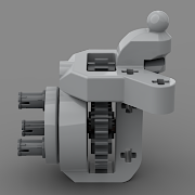
Thanks for the good questions! There are a couple of reasons for the difference, mainly to make the rear one space efficient. The key limiting factor is the CV joint in the drivetrain, the length of that is fixed. With this setup on the rear, it is enough to have only 1 CV joint, while in the front it has 2 CV joints, saving 3 studs of space longitudinally. The single U-joint results in a positive caster for the rear axle, which is acceptable, but in the front it would mean a large negative caster, which would be bad, both for the suspension and the steering geometry. So in the rear as the axle is not parallel to the chassis and the caster changes upon articulation, you cannot have two more links. This setup is like the lego ball-joint setup, but without the ball-joint itself, as that would take up too much space to fit in due to its limited connections. In the front, you must have a proper 4-link suspension to have good geometry, and also to allow linkage based steering. The Panhard rods don't limit the flex, they are designed to be as low as possible to also not result in side-to side movement or bump steering (it is parallel to the steering link). In the rear it is actually essential to minimize the side-to-side wobbling, because of the single CV-joint setup, that cannot follow side-to-side movement, and side-to-side movement would put friction on the driveshaft. I think however that this setup only works well in a smaller, lighter build, and at slower speeds I guess. For bigger heavier models you'd have more space longitudinally and you could add another CV-joint to the rear as well. You can see more images of similar axles in my other thread about the different small chassis variations, they share the same concept. Another good property of this rear setup is that the springs are positioned much lower than in the front, that keeps the rear bed clean, where the battery hub needs to be placed (which can be a problem for bigger battery hubs like the Technic one), otherwise the springs would end up colliding with it. -
That's what I wanted to ask as well. Maybe better in the Liebherr thread. Well I agree that it was not needed neither in the Ferrari nor in the skidder, but that does not automatically conclude that it was designed for the Liebherr crane. My guess was that it would be required for a faster RC car, like the upcoming Audi (if that's motorized), because for slower stuff, the red one would work as well.
-
That's an interesting proposal, never heard that before. Where do you get that from? It isn't unbelievable, but I guess that would mean that the drivetrain is fundamentally different from that of the Liebherr excavator and the Cat dozer (even though the Cat did have a differential, it did not have to take significant load as it was only for driving the fake engine). So I guess a heavy duty differential would only make sense if the drivetrain would be more sophisticated, for example using an adder mechanism, like in reality. But that would mean that one motor would be used for drive, and one for steering, which would put a lot of stress on that one motor and the drivetrain for such a huge model. So I am curious how that could work out.
-
The guys before you just concluded that it is indeed the crankshaft, and not a part that fell off, an I think they are right. It's not hitting the beam, it just appear so due to the perspective.
-
Pathfinder RC SUV [MOC]
gyenesvi replied to Daniel-99's topic in LEGO Technic, Mindstorms, Model Team and Scale Modeling
I have to admit it took me quite some time to read through this long writeup, but it is really deatailed and informative, thanks! Great that you shared all the difficulties about dealing with things at higher speed, apart from melting parts, such as proper suspension geometry. Nice testing methodology to keep improving your build! And the result is pretty convincing, congrats! It is true that sometimes I am dreaming of such components being available to be able to build cars with realistic suspension and drivetrain setup. It is a pity for example that such a trivial motor setup that you have there is hard to achieve in itself due to the sizes of the motors, not to mention the very weak performance if that would be built from lego components. Btw, I like the crawler setup you have there, I recently bought such tires and I am eager to test them in a future project. Cheers! -
[MOC] Toyota FJ40 RC
gyenesvi replied to gyenesvi's topic in LEGO Technic, Mindstorms, Model Team and Scale Modeling
Thanks! Yeah, the rear clearance is a bit small for the articulation, but with the custom tires it does not matter, it does not get stuck in the fender even when it touches it (the lego buggy tire can get stuck a bit unfortunately). But I did not want to change that part because it's clean and simple this way, plus the real one does not seem to have more clearance either. -
Oh, okay, thanks, I get it now, so you only need to switch what the left/right sides are doing wrt each other, and that can happen inside the body, that's nice and simple!