
gyenesvi
-
Posts
2,396 -
Joined
-
Last visited
Content Type
Profiles
Forums
Gallery
Everything posted by gyenesvi
-
42160 Audi RS Q e-tron
gyenesvi replied to keymaker's topic in LEGO Technic, Mindstorms, Model Team and Scale Modeling
Great reviews, looks great! I am happy as well that all new parts turned out to be as speculated. Really looking forward buying this one and see what else can be built from it! Don't care about the facial expression, but I do find it weird that you are often calling new sets legendary. In my mind, something becomes legendary over time, so new stuff cannot be legendary by definition. -
@recklessGlitch, really cool video! As I was watching, I totally understood many stages of your frustration. In the beginning when the PU system came out, I saw a lot of potential in it, but along the way I was sad to see that it does not live up to that potential. It's mostly problem with software/firmware (though the HW as a system has problems/inconsistencies too), but it would be great to see how far it could get if only the software part would become as good as it could be. Which sounds simple, but apparently is not, as it seems. SW development being outsourced would explain a lot..
-
The TC25 contest discussion thread says so in the voting rules.
-
I have to warn you about something in that comment of mine; I noted that for the case of crowd voting! But this contest will have jury voting, so I don't think it will hold for this case, because the jury will not vote just based on the looks and the size, hopefully. Other than that, I think the choice is not bad, it's a good challenge. I also think that reducing the gearbox from 8 speeds to 4 speeds is okay. I'd try to keep the differentials though, and that seems doable with the new double ended CV joints of the Ford GT. About electronics, I actually like the option of taking a set that originally uses electronics and making it manual, and Jim said that such a build could actually make a good entry. Can't that be done with one of your original ideas?
-
Sure you can tweak and limit things a bit in the controller as well (and I do that too in order not to put stress on parts), but for best effect, you really need physical stoppers, and it's best to have them close to the wheel hub somewhere for precision. On one had, you want to max out the turning of the wheels in response to the motor movement. On the other hand, you also want to minimize unwanted steering movement due to bumps hitting the wheel and pushing it to hit the chassis / fender or whatever you have there. That's why what I usually do is limit the steering rack precisely, and sometimes even limit the wheel hub on the other side of the rack. But yeah, I also do sometimes limit the movement right at the motor as well, so that it does not even try to rip things apart, though that limit needs to be a bit more loose to allow for enough movement even when taking lag in the steering joints into account.
-
Thanks for the new contest @Jim! I was wondering if it's worth thinking in shrinking a motorized set into a manual variant? There are some large motorized sets out there, and getting rid of the electronics often frees up space, so it would make sense on one hand. Many functions could be kept, just manual instead of motorized. Would that loose on the criteria of staying true to the original, or is it the functions that are more important, and not how they are driven?
-
Sounds great, thanks for showing the tweaked structure. Oh, okay, indeed, that was about BC2's inability to do auto calibration at the time. Not sure if it has been fixed already since then.. And yes, those black towball pins are there to limit the steering exactly where it needs to be, to allow good steering angle, while not oversteering. The physical stopper you built could allow a tiny pit of oversteer, as it allows a bit more steer than mine. The CVs could take it at slow speeds, but since this is a faster one, I did not want to risk wear on the joints, and it already has quite good steering angle at this point. Thanks, glad you like it! Sure, I am always looking for such possibilities, though I have not gotten there yet. I do have geekservos for steering, but I don't have yet a drive motor, I'd prefer something that has some custom (maybe printed) housing and axle output to make it possible to build it into the model properly, and maybe something that's a bit slower, or otherwise I'd really have to upgrade the whole drivetrain with metal joints, shafts, ball beared O-frames, differentials, wheel hubs, etc.. I guess it works okay in small scale, RWD without all these, but when you want to have a larger model and full drivetrain, I guess that changes many things.
-
@langko, thanks for building this and posting pictures; it looks really cool in DBG :) Glad you like the result! I have to say the idea with the M motor for the fake engine is pretty neat! At first I thought that you threw out the piston engine and just use kotor to spin the fan, but now I see that you actually managed to keep the pistons underneath, right? That's pretty practical indeed, it can be run independently. As for the calibration, what was wrong for you? Did it push the mechanism aprt somewhere? As far as I remember it calibrated okay for me with the Buwizz app as well when I tried once to control it with a tablet, but it was pretty uncontrollable that way, so most of the time I was using the BC2 app, and that could not do autocalibration for the Buwizz at the time, only manual. The physical limiter right at the motor seems like a good idea for that case if it does jot decrease the steering angle. I still have this one built so I might try these mods. Curious about the engine especially!
-
42160 Audi RS Q e-tron
gyenesvi replied to keymaker's topic in LEGO Technic, Mindstorms, Model Team and Scale Modeling
Do you mean the inner rotating part (that has the pins) coming out? I would actually guess that this new hub might be packaged as a single piece like the planetary one. With the new CV joint head it would not be possible to make the inner side separate and push it in from the outside, like the old one, so it may be only possible to have it preassembled. Which would make it inseparable. -
42160 Audi RS Q e-tron
gyenesvi replied to keymaker's topic in LEGO Technic, Mindstorms, Model Team and Scale Modeling
There is no room for a pin connection next to the new CV joint head, as it is wider than 1 stud, so the only option seems to be the fixed one. Unfortunately not too much is visible on this image, but the hub part itself seems a bit wider though, like the planetary one. I hope the play in the rotating part will be less than the old one, something like the planetary, which is better in that respect. Or even shorter, 2L or 3L, or something L shaped with a towball socket. That would be more useful for solid axles. -
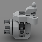
Although there are good sounding concepts in this post, from the badly translated marketing text it is hard to understand what the real potential is here. I understand that you are selling a motorization kit for this specific model, but a professional solution for lego is all about compatibility and buildability. So is this a system, or is this a one-off kit? I don't quite understand from the text if you claim to have solved all problems related to this model, or in general in a systematic sense, so can you please explain a bit more: What individual components are available in what form factors and sizes? For exmple the size / shape of the motor + planetary reduction is hardly visible on the image. Where is the steering servo, what is it like? How can it be used for other purposes, such as gear shifting? How can I build them into my models? What are the mounting points? What kind of drivetrains / suspension geometries are targeted? What are the sizes and connections of the metal joints and shafts? Are there differential frames in other form factors? This H frame is not useful for building floating axles, which covers most off-roaders in lego. Can parts be bought one by one? I am not interested in this one model, but I'd like to build my own ones. And indeed, seeing it in action would be much more useful than the text. Also, links to actual products.
-
[MOC] Toyota T100 Baja
gyenesvi replied to SpaceHopper's topic in LEGO Technic, Mindstorms, Model Team and Scale Modeling
Great looking build, looks really nice, like others, I like the livery and all the details. I'd also be curious about some technical features like drivetrain and suspension. For example, the front fenders look really tight around the wheels. Does it steer without getting stuck in the fenders? Those buggy tires get caught up really easily in anything around them.. -
Haha, no problem :) Well the difference between that and your current one is that in my case the steering rack is behind the axle, and because of that it has ackermann steering, not anti-ackermann. So flipping your front axle to have the rack behind the diff would improve it. I think the steering radius is okay on that one (not as good as the other buggy above, but good enough for such a buggy), so if that's a simple solution for you (I think you have enough space behind the diff) than maybe it's worth giving it a try first.
-
Many of my models on Rebrickable employ such steering geometry, but they are for floating axle suspension, not independent, which is slightly simpler to build, but the geometry part is the same. They have paid instructions though. Maybe it's best to look at this thread here on EB, which has detailed images of the axles and the steering geometry is quite visible. I'll also try to reformulate my comments above for better explanation. Your current geometry has two problems now (anti-ackermann and low steering angle), due to where the steering links are attached to the planetary hub (red ball joint). To solve the anti ackermann, you'd want to move the ball joint one stud out towards the wheels. That alone would be problematic, as it would then collide with the wheel. To increase the steering angle, you'd want to move the ball joint back one stud. Luckily, if you move it back and out one stud at the same time, then it solves both problems and it will not collide with the wheel (you may also need to lower it one stud..). Then you will arrive to the geometry I have in the model I linked above. In order to do all these, you steering rack will also have to move back one stud and become one stud wider as well. Hope this helps!
-
General Part Discussion
gyenesvi replied to Polo-Freak's topic in LEGO Technic, Mindstorms, Model Team and Scale Modeling
That's not necessary a positive thing. Now they are not pressured to use all those extra parts in a future set.. Did the Ospray contain the tapered flat panel as well? I wanted to have that one but Bricklink does not even list it in that color. Or is that something new, maybe for something upcoming? -
Nice ambitious project, but could work out with all those non-lego components. Indeed, your steering geometry is anti-ackermann now, which does reduce steering radius in my experience. If you want to place the steering rack in front of the axle, then you cannot move the ball pin one stud inwards if you want to maintain good geometry. The other thing is that your rack is not as close to the center of the axle as possible (longitudinally). Now it is 3 studs away, but it could be just 2 studs away. And then you can get rid of the anti-ackermann geometry too (the linkage will not hit the wheel as you move it outwards sideways), plus you will have better steering angle, because the link will be shorter (the same amount of rack movement will turn it more). But for that you need to make space for it, and you'll have to redesign the mounting points of the A-arms. Also, as an unfortunate consequence, as the steering link gets shorter, more power will be required for steering, but that won't be a problem I think, the servo will be plenty strong in this setup. The steering rack will get more complicated as well, it will have to be 9L, while still going around the differential..
-
Shelby GT500 12studs
gyenesvi replied to gnat_bricks's topic in LEGO Technic, Mindstorms, Model Team and Scale Modeling
Looks awesome, nice and clean design, and one of my favorite cars :) -
General Part Discussion
gyenesvi replied to Polo-Freak's topic in LEGO Technic, Mindstorms, Model Team and Scale Modeling
I've been thinking along those lines as well. But then my question is why start recoloring with the frictionless version and not the friction version? The frictionless one is used less and in a visible spot less often than the friction one. And the frictionless also exists in grey. Recolorings seems a bit ad-hoc to me, they seem to really happen for the sake of one set, often licensed or themed, instead of a planned way by thinking ahead what would make sense systematically for many sets. The black 16T gear also only happened for the sake of the PacMan set, not for a technic set. Though it's true that such things stand out more in creator builds than in technic builds, which are more about looks anyway. -
General Part Discussion
gyenesvi replied to Polo-Freak's topic in LEGO Technic, Mindstorms, Model Team and Scale Modeling
I have also made this observation, so I tend to agree. Quite a few basic technic connectors are missing in basic colors and are causing color inconsistencies in official sets. The latest example is this part in green in the John Deere Skidder. The same piece was missing in orange from the Ford Raptor, though it became available since then (I guess because of the F1 car). Also the 1L liftarm in orange was missing for long, only available recently (still missing in green though). I wonder if that pink connector in the parrot was actually made for the parrot or also for something else, like a flower set. Pretty sure though it was not made for a technic set. The half bush would be really useful to have in basic colors like black (exists but very rare), dark grey, red, etc. The white we got may as well be useful though.. I guess pins are a different story, they are intentionally not all made in black because it would be really hard to differentiate them. The strange recolor mentioned above seems like a weird case though, wonder what's the explanation. -
42160 Audi RS Q e-tron
gyenesvi replied to keymaker's topic in LEGO Technic, Mindstorms, Model Team and Scale Modeling
I wondered the same. I do think it is misaligned by half a stud on the wheel hub end, but I can see on the 360 video that it has those red connectors on both linkages (in front and behind the axle), and I think the two together sort of cancel out the effect and keep it straight (push/pull the wheel in both directions equally; the misalignment might even result in a linkage with less wobbling). Otherwise I think a misalignment would be noticeable in this somewhat faster RC car. -
42160 Audi RS Q e-tron
gyenesvi replied to keymaker's topic in LEGO Technic, Mindstorms, Model Team and Scale Modeling
That's an interesting idea I also thought about but I doubt TLG would deem that stable enough, even if the half stud part had friction (which does not exist either in any pin). -
General Part Discussion
gyenesvi replied to Polo-Freak's topic in LEGO Technic, Mindstorms, Model Team and Scale Modeling
Well if they are frictionless then they are not going to be used in place of the blue ones, at best in place of the tan ones. -
42160 Audi RS Q e-tron
gyenesvi replied to keymaker's topic in LEGO Technic, Mindstorms, Model Team and Scale Modeling
The steering linkage seems to be doubled up just as in case of 42099. I was wondering whether the new wheel hubs will have the steering arm in the middle as the planetary hub has, or offset one stud as the regular wheel hub has. Based on the position of the red piece, I'd guess its offset. Also, my guess is that the hub will have the towball integrated, just like in case of the planetary (otherwise the pinhole would collide with the CV joint's head). Also, I have been wondering about the speed of the model. If the gearing is 1:1 to the diff from the motor, it should be about 2x faster than 42099. With slightly weaker motors, but also with a ton less friction in the drivetrain. Wonder how that will actually play out! -
General Part Discussion
gyenesvi replied to Polo-Freak's topic in LEGO Technic, Mindstorms, Model Team and Scale Modeling
That sounds like a pretty stupid color choice for a part that's never really visible for the most part. Also Rebrickable says there's a color error there, and the set has them in blue as well. Or is the color error because it's supposed to be a new color not yet in the inventory of parts in general? On the other hand, it would be great to have this in black again.. -
[MOC]◄URAL 4320 6x6►[2023]
gyenesvi replied to Michael217's topic in LEGO Technic, Mindstorms, Model Team and Scale Modeling
Great, looking forward to it! What I was curious about is how the drive is transferred onto the axle, that's the interesting / unusual part, and the bottom image did not show that, but now I found the top image and I can see. I was wondering how you braced it. Unfortunately I am afraid that on challenging enough terrain if you push it hard that gear mesh between the 20T tan gear and the red differential gear will prove to be the weak link as it is not supported by a rigid piece on either sides immediately next to the gears and the axles may have enough space to bend (especially on the middle axle where the axle holding the tan gear does not go from side to side but is split in the middle). Maybe with 3 axles / 6 wheels and planetary hubs and open differentials it won't be a problem, it's hard to tell, that's why I'm curious about an actual ride on tough terrain. Would be nice to know if such a setup would be reliable on a truck trial :)