
PorkyMonster
-
Posts
183 -
Joined
-
Last visited
Content Type
Profiles
Forums
Gallery
Everything posted by PorkyMonster
-
 Like this video in this thread?
 -
Nose alone, I prefer the left. But looking at the car as a whole, I do agree with you that the right nose matches the rest of the bodywork better.
-
H? I thought Hammer Head was good? LOL *joking* Yup, looks even better now with thinner and darker parts at the front grill (actually thought you would never change them).
-
Oops, you responded too fast. I've edited my post with more details already. Basically one needs to note the rest position of the wishbones. If you ensured that they are horizontal while the car is stationary, you're on track to gain negative camber as it moves and turn (this, you're right). However, if the wishbones tilt downward from the chassis at stationary, then you'll end up gaining positive camber first, before gaining negative (assuming your suspension will compress until your wishbones start to tilt upward).
-
(1) You meant caster? Worm gear - I meant this. (2) Not exactly true. Shorter upper wishbone alone will not add negative camber when compressed, unless you have long suspension travel (such that it compresses until both wishbones tilt upwards from the chassis). You can verify this easily by constructing a simple trapezoid and see what happens when u hold one non-parallel side fixed (representing the chassis), and lift up the opposite side (that'll represent the wheel). The point when both wishbones are horizontal is the point to note - from that point, the more they tilt down from the chassis, the more negative camber gets. Same thing from horizontal to tilt upward. But as your suspension travel from the wishbones tilted down, then horizontal, then up, your camber actually went from negative, positive, then negative...
-
You're right. 3 of them would be strong enough. I lubricated them that's why I went for 4 .
-
Interesting creation . I have two concerns though: (1) About the pulling left/right - can be solved with about 11 or 14 degrees (i.e. 1 x 5 or 1 x 4 studs) caster angle. Also, including a worm gear between the servo and steering rack will help. (2) And for the different length wishbones at the front axle - wouldn't that introduce increasing positive camber (i.e top of wheel is further out than the bottom) the more suspension compresses? Positive camber is not desirable as it reduces traction of your front wheels when you turn. With these handling issues resolved, I'm sure you can go for greater steering angle.
-
While playing around with the small turntable, I realised it can also be used to make a strong open differential, as follows (the red part of the differential need not be present, depending on usage): Top view : Side View : (lxf) I'll be using this as the center differential for my "Yet Another Supercar (Gen II)" . Another good place to use this is in mechanisms that uses those inner gears of a differential heavily - e.g. automatic transmissions that rely on a differential to detect overwhelming torque.
-
I think this is very nice already. Not sure about viewing from other angles though . PS. Oops, I just noticed the side mirrors... they spoil the image of a supercar... although they might fit the "rugged" part...
-
Like others, I marvel at the flying headlight too But mounting/attachment issues aside, I think it showed that the car body has been receiving quite a lot of the bumps (i.e. not protected by the suspension) - can consider adding some dampening mechanism, longer suspension travel or harder springs (I cannot be sure as I don't have the porsche set). Overall, I really like your work, and I might seriously look into how you did the gearbox/switching and learn from that .
-
Wonder if the design of the front "Grill" can affect how the lights look... those LBG parts in front looks rather strange to me have you tried thinner and darker materials (e.g. axles)? Also, for more "piercing" look you could consider a sharper nose with lights slanting back more prominently? PS. I do create hideous models so don't take me seriously if my suggestions don't sound right... LOL.
-
Shouldn't it be "whatever you're comfortable with"? I think there is no standard answer or suggestion here... after all, "modelling" can range from highly realistic to highly abstract. For me, I'll just go with whatever I feel like doing and enjoy the process of modelling, rather than worry too much about what others want to see...
-
Yes, I've tried the friction solution before. First of all it's not foolproof (even more so as the model gets larger ), secondly, while it does 'shield' the steering wheel from the effects of hitting bumps (note that this does not necessarily mean that the tyres won't deflect and continue down a new path), it does not help in terms of steering 'responsiveness' (especially after gearing down from steering-to-tyre) - when you rotate steering wheel by 5 degrees, for instance, I hope to see slight tyre rotation as well, however small that might be.
-
Yes, will need a few half bushes to lock the worm gear in place. I think that can be achieved. No, servo is unlikely to be forced out of center. However, in scenarios where a servo is not engaged (e.g. if I choose to play in manual mode), the steering wheel can get forced out of center easily.
-
Not sure if anyone has had something similar, but here goes... In creating my models I observed two issues with steering: (1) Lego's pinion and rack steering mechanism allows for the turning of pinion by a mere 1/4 to 1/2 turn each direction (unless you use a long track, which may not fit in most models), and when connected to a steering wheel, some gearing down may be needed for more realistic 'feel' (i.e. u turn more on steering wheel for that 1/4 to 1/2 turn of the pinion gear). This gearing down worsens the play involved. (2) Bump steer - in push-along vehicles, you have to hold on to the steering wheel at all times, or else the wheels will veer left or right happily when you just push your vehicle freely. While there are ways to incorporate "return-to-center' behavior, these won't solve problem (1), and will add more load to the servo (if connected). So I thought of one way to solve these two problems at the same time - placing a worm gear in between, as below (worm gear in red): (lxf) So, from the rack and pinion, there's the worm gear, followed by 3 sets of 24:8 gears - axle from the first set can go to the steering wheel, while the axle from the 3rd set goes to the servo. I believe it is possible to make the structure more compact, and I'll do that when I get down to creating my next model . Any thoughts?
-
Oops... right, I relooked at the video - looks like yellow knob wheels at rear, black ones at front. Btw, do you happen to have an underbelly pic? I'm keen to know how you made use of those yellow knob wheels underneath.
-
JJ2's Custom part designs
PorkyMonster replied to JJ2's topic in LEGO Technic, Mindstorms, Model Team and Scale Modeling
-
JJ2's Custom part designs
PorkyMonster replied to JJ2's topic in LEGO Technic, Mindstorms, Model Team and Scale Modeling
Based on my limited experience, another gear that often slips (and therefore probably require a 'hardened' version ) is the 20T beveled with the differential housing, when used in either a RWD or FWD model (but in AWD, it's often the 12T within the middle differential that slips). -
From the video, looks like u'r using different gear types for the axles - knobs for front, and usual half-beveled for rear... any practical reason other than parts availability? btw, I particularly enjoyed the video from 2:57 onwards
-
That is the beauty of Lego - allows for endless trials and errors... and the urge to dismantle and start all over again invariably grows over time as new ideas emerge... but, I kinda like the way you designed your wheel arches though - very flexible, yet solid, design that will suit ANY WHEEL SIZE ...
-
Thanks . I like to observe suspension at work, especially those with some sort of dampening, that's why I included that segment .
-
Very sturdy chassis. I will incorporate more 5x7 and 5x11 frames in my next build .
-
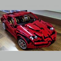
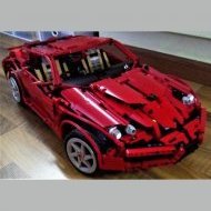
Here's the video, hope you guys like it, comments most welcomed
-
One thing that I still can't figure out how to include is Ackermann geometry - primarily because if I forgo parallel (i.e. one to the front and one to the back of the front axle) steering links, my front wheels will go out of sync and one of them will not be able to recover from the steer (likely due to the weight of the car). Still thinking... Indeed, the 3L thin level will not slide over the 3L axles with knob - friction between them is strong enough to prevent that. Here's the detailed, more accurate, front axle that I'm using: (lxf file) I've shamelessly adopted the slanting 5L thin level idea that I first saw in your Steppenwolf platform as I think the way it links to the lower steering arm can allow for more ground clearance. But I've modified other portions to suit my model. Caster is realized by tilting the entire front axle relative to the chassis, because that will allow my suspension travel to be in the same direction as the caster angle. Thanks!! I fully agree with your suggestions on parts 32187, 6558, 48989 as well as all the LBG parts, and I'll see what can be done (as I don't have certain parts) that's the beauty of Lego - many ways to implement the same effect. Could you clarify on the wheel hubs part? ( couldn't quite understand what you meant...). But related to the wheels, I'm considering adding this rim cover: . That's on the way .
-
Two more photos: and