Search the Community
Showing results for tags 'nxt'.
-
Hi, my NXT Axle Sorter is finished. This machine works with a Lego Mindstorms NXT 2.0 and an IR Link sensor. The little car that you see puts the axles in the right containers. The large 'building' with AXLE measures the length of an axle with the color sensor as you can see in the video. The little car drives over some gear racks. The ultrasone sensor reads the distance and the IR Link sensor sends the signals to the little car. Here you can see the inside of the machine: The machine sorts normal axles. Also the new colors (example: the red 4) If you want to sort your axles you need to do these five steps 1. Put the axles in the machine 2. Press the button on the NXT 3. Have a drink 4. Take the containers with the sorted axles out of the machine 5. Make your next Lego Creation If you want more pictures about some details, let me know. Here is the video:
-
 At our Flickr page you can view the photos of our visit at Lego World 2016 in Utrecht: https://flic.kr/s/aHskMd9EAj. A video is also available: Enjoy, Hans
 -
For our Sioux.NET on Track project (see https://siouxnetontrack.wordpress.com), we not only write a PC application in Microsoft.NET (C#). But we also write quite some code that runs on the EV3 bricks. In this article, you'll find programming tips & tricks for the Lego Mindstorms EV3 programming environment. Is it possible to have two or more EV3’s in Daisy Chain mode and use WiFi to connect to the PC application? Yes, you can. Read the full article how you can achieve this at the blog: https://siouxnetontrack.wordpress.com/2017/04/08/how-to-ev3s-in-daisy-chain-mode-plus-wifi You can use two or more threads in parallel to run on an EV3. But how do you synchonize them? Read the article how to do this at the blog: https://siouxnetontrack.wordpress.com/2017/04/02/how-to-synchronizing-two-threads/ More to come later. Enjoy, Hans (moderator of our Wordpress blog Sioux.NET on Track)
-
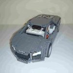 I created this modified Bucket Wheel Excavator some time ago, and I thought I would like to share it on this forum. After building the original BWE, I wanted to try to incorporate some Mindstorms functions into it. I managed to motorise all the active functions, using both an EV3 brick and motors, as well as some PF motors. Functions can be preprogrammed, or can be remotely controlled using an EV3 IR remote. Here is a list of the functions: Bucket wheel rotation and main conveyor belt - PF XL motor Lower conveyor belt - PF medium motor Boom arm elevation - EV3 large motor Lower conveyor swivel - EV3 large motor Superstructure rotation - EV3 medium motor Driving - EV3 medium motor Since I owned an NXT as well, I used it to motorise the small mining truck that was included in the set. There are also some LEDs that illuminate the 'work area', but they don't really do a good job, its just a nice thing to include. Here is a video of the excavator in action, as well as the mining truck (sorry about the poor resolution and bit rate): More info about the machine can be found here: https://www.us.lego.com/en-us/mindstorms/community/robot?projectid=3e125a5b-475c-4a4c-b3ed-e4b4f2192907 Let me know what you think of it in the comments!
 -
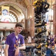 welcome to the mindstorm section of the Akiyuki project, this topic is for the modules of Akiyuki that have mindstorms in them or use mindstorms in any way. as always I would appreciate any information (pictures/videos) of these modules working or built here's what I know so far: Ball Cleaner EV3( in progress by @Juroen) program by Akiyuki (stud.io file available instructions coming soon) Container Transporter NXT instructions available here by @Courbet program by @9v system available here Fast Ball Sorter EV3 instructions by Courbet, built by Courbet and Mogwai, program also by Courbet and Mogwai, Render by Blakbird(instructions available) building instructions, program for the ev3 any help would be good to get these modules made into instructions (programs will also need to be made) 9v system
 -
 In this video, I show you what exactly comes in the 9797 Lego Mindstorms NXT Base Set with this stop-motion style unboxing. If you liked this video and would like to see more unboxing videos in this style, please let me know!
 -
At our Youtube channel, you'll find a video of our fully automated train layout. It will be displayed on Lego World Utrecht 2015 from October 25 (Sunday) until October 27 (Tuesday). The video shows the layout in our test room. The train layout contains eight EV3 bricks and one NXT brick to control all the Lego objects. The layout is controlled by a PC application (Microsoft.NET) that has been written by our team. Enjoy the video and maybe we'll meet in Utrecht. /Hans
-
My first NXT creation! A Lego Mindstorms NXT pinball machine featuring 3 interactive servo motors, 2 touch sensors, and a light sensor! Flippers are activated via Touch Sensors on either side of the machine. Features auxiliary high-speed spinner. Makes for hours of fun and awesome gameplay! Programmed in NXT-G. How was the video style? Was it engaging? Did you enjoy the video? I am also extremely busy with virtually no time whatsoever to build, so unless I am extremely motivated, I won't be able to build anymore for a little while. I am open to suggestions of future builds, though!
-
 Hi all. Here's a brief video of the EV3 floor roving robot I've been working on for the past few days. It's pretty crude but can go a long time without getting stuck. It makes use of one distance scanner in three positions by using a clutched IR sensor, has two bumper sensors that are padded by shock absorbing springs to reduce impact on the touch sensors. Behind the bumper is mounted a color sensor on the front that is used to measure near distance and ambient light. It appears to flash because it's rapidly switching between measuring these two things, With this sensor it can detect objects near to the ground that the main sensor peers over, and also back out of shadows so it doesn't get under furniture. Working on the software has been the long part as there is much debugging to do and each test run can take a long time depending on what I'm trying to improve. It makes decisions based on distances to its surroundings on three sides, so if it senses it's coming up on something in front of it, or a bumper strike is detected, it will choose to turn left or right depending on which direction is more open.
 -
I made a printer
technical posted a topic in LEGO Technic, Mindstorms, Model Team and Scale Modeling
This is an early proof of concept before rebuilding it completely: Running down the pen: I built this printer LEGO parts. It prints pretty well with markers. It prints in dot-matrix and line modes. I did this with an unmodified EV3. Some of the work was creating huge binary files to print from. Video: -
 I've been testing leJos with my old NXT brick and something seems to be wrong.When I flash the brick with latest leJos firmware, it works fine. After some time, it starts spewing some garbage onscreen: The only thing I can do is press Off button, but then it doesn't boot up again and I need to try multiple leJos/official firmware reflashes to get it to work. Has anyone encountered anything like that? Any help would be greatly appreciated.
 -
weight(only Lego parts): 1300g weight(with cutting board and knife): 2000g lenght: 50s width: 45s height:45s The main function of this device i cutting fruits in squares. For the driving part i used 2 motors, one of this motors move a knife. Second motor is responsible for driving. This machine also have a safety system. When you move hand in front of knife, everything will stop. After cutting, the machine pushes the fruit into the bowl. "Agresive mode" - this is my brother's creative idea... All functions can be seen in my movie. Have a nice watch. :)
-
 Hello everybody. Recently i found a segway program on ntx with extension .rbt. I need to convert it into .ev3.I tried, but it didin't work. Who can help me?
 -
Hello friends, It is I, elrid from india, and I am of having difficulty sending sounds over bluetooth to a second NXT. I have a master-slave relationship between two of my best NXT specimens, but one of them does not have working speakers (even the startup noise doesn't work my friends!!!). So, I am of trying to get the first NXT to signal one of another NXT with speakers work over bluetooth connect. I use BrickxCC language. Any help is appreciate. Thank you friends! I am see with my eyes there is individual named DR_SPOCK who is very helpful and handsome. Hopefully he can help.

-
Dear All, there are numerous contributions on electrifying LEGO train switches, including those here on EB. All-LEGO solutions, all-custom solutions and “everything in between” has been presented. One issue for my layout was: How to control about 30 electrified switch points on a fairly large and rather congested layout with many areas not readily accessible – in a purist solution? Using individual cables going from one single “control center” to the switches would result in some considerable cable mess. Alternatively, PF receivers may serve as remote controllers on “PF layouts” – manipulated via IR light from the center. That is a very elegant solution, however, there are only 4 x 2 IR channels (or 8 x 2 in extended mode with a mandatory custom remote control program), which is not enough on my layout, particularly when running several PF controlled trains eating up channels as well. One approach is a fully LEGO based solution using LEGO programmable bricks (PBricks). With such PBricks one can use a variety of motors on the drives and also some fairly flimsy switch drives because of power and timing control of the drive train. Furthermore, with some software development (e.g., NQC, RobotC, NXC, NXT-G …) the controllers may get their own “address” and operation software. However: Cost may become an issue: You need 1 NXT or 1 RCX for each set of 3 switch drives, or 1 Scout for each pair of 2 drives (in case the drive is operated with one additional MicroScout, the Scout can also operate 3 drives) … More recently, LEGO compatible 3rd party switch drive controllers have become available: The 4DBrix (https://www.4dbrix.com/) varieties are extremely nice! What I find particularly intriguing is the control software. The entire product line from switch drive, controller, to full software integration is the best LEGO compatible solution I became aware of. Nevertheless, here is my all-LEGO “solution”: Brick-built switch drive controllers equipped with PBricks. Please don’t take this post too seriously. It was a lot of fun to build these – plus I like to see stuff moving and making noise (in addition to trains that is) on my layout. Since a video says more than 1000 words, here is the “visual summary” of the rather long write-up following below: And here are some more detailed descriptions ... Working principle The idea of this approach is rather old; in 2007 this article in Railbricks Issue #3, page 44 illustrated some details: The controllers serve more than 3 switch drives with only one PBrick by “mechanical address decoding” – or whatever you want to call it. At that time though I did not think about “simple” motorized switch drives; the ones I used then were all equipped with MicroScouts and were designed to run only with these. That limited the applicability of the controllers on my layout significantly: You need to turn on a MicroScout and put it into “P” mode to let it do what is expected from an electrified switch drive. However many of the switches are hard to get to – hiding behind bookshelves and underneath/within furniture. I have thus added mechanical switch drive controllers for operation with NXT, RCX, and Scout PBricks operating most of the LEGO electrical motors, including PF. So far I have electrified all my switches and bunched them up in “groups” using four such switch drive controllers. What are the controllers supposed to do? They serve as “local remote control hubs” for a group of switch drives. There is essentially only a purely mechanical “bricking” limitation on how many switches can be handled by each controller. The controllers have a dedicated address, for simplicity let’s say address 1, 2, 3; the individual switch drive is hooked up to the respective switch drive controller and has a local “address”, let’s say a, b, c, … The last bit of information required is the switch position, let’s call that “straight (s)” or “turn (t)”. The information sent to all the controllers on the layout is then “controller address + local switch address + switch position”, for example “2, d, t” means that switch “d” operated on controller “2” should go into “turn” position. As shown in these posts here and here, all communication on my layout is via the LEGO IR messaging protocol, mostly transported via RF. Figure 1 shows a “bare” Scout operated switch controller without any decorative stuff; Figure 2 a controller with an additional decorative brick structure remotely matching the Toy Story steam engine coaling station, Figure 3 a controller that is residing within a “building” remotely matching (if at all) the appearance the #10027 train shed – however with a rather “transparent” roof (in fact I got hold of 50+ of transparent #41750 pieces for free and all were left handed … what to do with them?). Figure 4 shows a more or less bare controller I built because I needed to serve 12 switch drives in locations under my desk and further away. All four work on the same principle, but use slightly different mechanical operating techniques. The Scout operated controllers in Picture 1 and 2 use the Scout’s Visible Light Link (VLL) terminal (“Output C”) to connect with MicroScout operated switch drives via an optical fiber link. In my opinion, TLC never really exploited the possibilities of the VLL link. They for example never produced optical fibers longer than about 20 cm, as far as I know. Rather cheap plain vanilla optical fibers (1 m for less than 1 €) are good enough. The controller in picture 3 runs with an RCX PBrick and uses PF switches to operate switch drives equipped with PF or 9V motors. It features a moving stage powered by a PF M motor and a Technic mini motor for actuating the lever throwing the PF switches. The controller in Picture 4 operates an almost identical stage. The stage drive is not mounted on the stage itself; the Scout drives the stage via Technic chain links (#3711) with a stationary #47154 motor and again a Technic mini motor (#43362) for switching. Common to all controllers is the “positioning” mechanism of the moving stage: In case of the optical controllers, VLL light from the Scout output needs to go through the corresponding fiber connecting with the MicroScout operating the switch drive. The fibers are simply pushed through Technic bushes into a Technic brick with holes, in other words they are always nicely lined up. So we just need to get the VLL light from the Scout to the corresponding hole. That is accomplished by either moving the entire Scout PBrick (see controller in Picture 2) or by moving the 20 cm long LEGO optical “fibers” (BrickLink ID x400c20). These are more or less plastic tubes that came with the ExoForce sets – finally I found a way to use them …) connected to the VLL terminal to the target hole, see picture 1. The Scout has a built-in light sensor; that one is used to detect when the VLL output diode is in line with a hole or somewhere in between by measuring the light intensity emitted from a LEGO light brick (9V or PF): When the light from that brick goes through a hole, the detector sees it “brightly”, when it is more or less blocked, it only sees a fraction of the “bright” light. When the “hole detection” mechanism is lined up with the fibers, we are done; this is readily the case when stacking Technic bricks with holes. Basically the same approach is used for the RCX controllers; here we need to get in line with the PF switch levers. When lining up PF switches directly next to each other, the levers are 3 holes apart, and we can use a simple optical positioning mechanism again to get to the right switch. The actuator of the moving stage for throwing the PF switches (see Figure 3 + 4 and video) is partly shown in Figure 6. Since the PF switch has three positions (“forward”, “0”, “reverse”) and the switch drive motor is turned on only for less than a second, the PF switch needs to be swiftly turned back to the “0” position. That is tough to do with powering the actuator motor accordingly. Furthermore, the lever needs to be straight up after switching, as the stage/actuator needs to freely pass the switches when moving to a new target. I have used the fairly tight 6.5L shock absorbers (#73129) to push the actuator back into “0” position after the switch was thrown. As mentioned, the switch is thrown with full torque of the Technic mini motor (PBrick output “full forward/reverse”) as the actuator has also always to push against one of the two springs of the shock absorbers. The output of the PBrick is then put into “float” rather than “stop” mode, so that the motor axle turns freely and the compressed spring of the absorber pushes both the PF switch lever as well as the actuator into “0” position. Programming the PBricks The programs running on the PBricks are rather straight forward. NXT, RCX, and Scout PBricks are all capable of multitasking. In my programs, one task is handling incoming messages. The moment an address is recognized by a PBrick as “my ID”, it listens very carefully for the next message(s) to come in; that one contains local switch address and desired position. The routine puts that message onto a stack, sends a “got that” reply and continues to listen for further messages to arrive. A second task watches the stack: Nothing here, nothing to do. Once there are messages on the stack it fetches one, analyzes it and drives the positioning mechanisms to the appropriate output, sends out either VLL light or briefly operates the PF switch by changing the driving Technic mini motor from “float” (off) to “forward” (or “reverse”) and then back to float. After completion it throws the message away and continues with the next one on the stack. How does each controller know, where the moving stage actually is? Upon startup, the stage is driven all the way to the right, until it reaches the “right limit” touch sensor. Then the light brick is turned on and the trolley moves all the way back to the “left limit” touch sensor. On this journey, the light sensor continuously monitors the light intensity. The brightest light value detected is then considered a “hole”; everything else “in between”. Then the trolley moves back all the way to the right touch sensor and on its way, holes are counted and each switch is thrown to get all switches into the “straight” position. Now we know how many switch points are present, we know they are all set to straight, and we know that we are at position “0”. Upon getting a message, let’s say “turn switch 5” it starts to move left and simply counts up holes. Once it arrives at “5” it stops and is automatically aligned with either a corresponding hole for the VLL output of the Scout or the lever of a PF switch. Then it either sends out the VLL forward/reverse command (Scout) for a given amount of time or it throws the PF switch (RCX/NXT), again for a given amount of time. The switch drive motors are turned on within a “hundreds of millisecond” time frame. This time is adjusted to the requirements of the switch drive. That is basically it. The VB6 program (I am old …) running on my laptop is showing my layout with all the track including switches. Basically the program is one database with some graphics and in/output around. Clicking on one of the switch symbols makes the corresponding real switch change its direction. The program searches the database and finds out which controller is assigned to this switch. Furthermore it finds out to which local output (a, b, c …) that switch is connected on the selected controller. Since the program knows the current status of the switch on the layout it composes a message as described above: Controller address + local switch address + new position and sends that out via the IR tower into RF space. There is a little more to it. To ensure rather secure communication between host computer and remote controller, there is a handshake protocol: The controllers acknowledge messages they understood. If there is no reply, the host control program repeatedly sends out the same messages. If there is still no answer for let’s say five consecutive attempts, a warning message tells that something is wrong. The controllers also have some safety routines – should the stage go beyond the end points it stops operating and sends an SOS message, and do on. Seeing this happen is real fun! However the SOS thing hardly happens at all … Another thing to notice is that MicroScouts go to “sleep mode” when not doing anything for about 10 minutes. So every 9 minutes or so, the stage is driven all the way to the left, then right, recalibrates the light sensor, and then back left, stopping at every hole and let each MicroScout play some sound. So they never fall asleep … and there is even more action on the layout. One thing I am somewhat proud of is that all that functionality is possible with 396 LEGO byte codes on the Scout controllers. The RCX PBricks have monstrous 8 kByte of storage space – I believe you could use an RCX to successfully fly to the moon, land there, play soccer, and safely return. These TLC folks are ingenious. And if you don’t want to run a clumsy computer based control program – learning remotes work also very well for easily controlling more than 30 switch drives. This was already discussed in this post. The number keys “1” through “9” correspond to switch drives 1 to 9. I first press one color key (ID), addressing a particular controller and then swiftly a number key. The controller that recognizes the address operates the corresponding switch drive and puts the switch to the “branch” position. Upon pressing the address and then number key twice, it goes to “straight” … Some files The LDraw mpd files for three controller types (Fig 1 – 3) are here along with the NQC programs here running on the PBricks. The controller in Fig. 4 is in the works). Please see readme files in the directories. Note that you need to have the official and unofficial LDraw parts libraries installed. When opening the LDraw files with MLCad, the program tells you that newer versions of some parts are available. Ignore that, otherwise the model may be corrupted. All LDraw files open correctly with LDView 4.2 and MLCad 3.5 Best regards, Thorsten
-
Dear All, since 2001 I am working on this: LEGO train layout control from one single computer (trains, switch points, light, bridges, …) using as much as possible original LEGO hard- and software. Still WIP but getting close. Most of the LEGO stuff used here is – since long – not officially available anymore. But LEGO is LEGO and lasts forever … and now I am close to getting it all to work. This project has survived Win98, QBASIC, WinXP, VB6 (well not true, still using it, see below …). And as sPy pointed out correctly in his reply on my PF RF hack, all this is building on stone-old electronics hardware. But: All this stuff is still available today. BrickLink is very close to LEGO heaven, I believe. And because nobody really cares anymore about RCX’ or MicroScouts – they have become dead cheap. I recently ordered RCX’ 1.0 with power jack for less than $20 each. These are the best PBricks ever made by TLC … imho, of course. There are many powerful and elegant solutions for controlling PF operated trains as well as track/track side-related functions such as remote switch operation, lighting, train detection, and much more. Most of these are based on home-built (as for example the myriads of wonderful Arduino-based solutions) or third party commercial devices, e.g. SBrick, 4DBrix/nControl, PFx Brick, and increasingly more. And this is wonderful. This post is just another one in this line. The difference is that I tried to use exclusively original LEGO stuff. Based on IR communication, it works perfectly well, but only within a range of about 1 m, which is not that good for train/track control ... So there was “only” one but significant modification required: Changing from IR to RF communication. This post illustrated how to do that. And if you don’t want to break into your PF receiver at all but just an add-on, this works also perfectly well, but is somewhat more elaborate. The ultimate goal of this project is to control diverse LEGO devices (PF, RC-train, RCX, NXT, Scout, MicroScout, Spybotics) from one device. In my case from a program running on my computer. However this could also be any device that can generate LEGO Mindstorms IR messages (which were introduced with the RCX, as far as I know), for example: A computer with one of the LEGO IR Towers attached, running the Bricx Command Center (BricxCC) software, A computer with one of the LEGO IR Towers attached, running any other program, which has access to the LEGO IR Towers; this includes the various programming environments and languages such as NQC, RobotC, or any custom program that has access to either a serial port for the serial tower or the LEGO drivers for the USB tower. (Note that on 64 bit platforms, the USB tower does not work anymore, since TLC never updated the required driver for the tower. In that case the stone old serial tower attached to a RS232-to-USB converter has to be used and accessed via a free COM port, preferentially in the COM1 … COM8 range. Works like a charm. Some people have trouble to get BricxCC or the original RXC 2.0 Mindstorms software communicate with the RCX only caused by the missing driver. Some revert back to 32-bit or even Win98 … not necessary!) Any of the RCX, Scout, or Spybotics, NXT(+IR Link Sensor) PBricks, Any learning remote, that was trained with any of the above means of generating LEGO Mindstorms messages; I am usually using BricxCC for programming. For testing purposes on my train layout, the programmed learning remote is very handsome: On my home-office style train layout (yes, I do work here as well), there are currently running/installed 8 PF trains 1 RC train 2 RCX controlled trains In addition to 2 RCX switch controllers (one serving 7 switch points using PF M motors, the other 12) 2 Scout switch controllers (one serving 3 switch points using 3 MicroScouts, the other 7) 1 Scout train bridge controller, see below 2 RCX light controllers with 3 outputs each, see below Each of the PBricks (RCX, Scout, NXT) have their own "personal" ID they recognize and respond to; the PF and RC trains are handled by the NXT PBrick (equipped with the IR Link sensor from HiTechnic) serving as central “PF/RC-train communications hub”. The NXT recognizes a total of 3 (RC) + 8 (PF) = 11 ID’s and maps these to the 3 RC and 8 PF channels: The NXT is operated with standard LEGO firmware (V1.31) and the LEGO NXT-G software environment is used for programming. Unfortunately the IR Link sensor has a very limited communication range, far less than any other IR light emitting LEGO device. This was one more reason for me – other than wanting no line of sight operation – to switch to RF. I have thus placed one of my IRRF transceivers (big words for not much, this is just what I am calling them) right in front of the IR Link sensor, which sends out every 38kHz modulated IR light it detects into RF space and listens for any 433 MHz signals in half duplex mode on a first come first serve basis: If IR light is detected then RF is sent out – if RF is detected IR is sent out. Both channels are dynamically mutually “blocked”; when an IR message is sent out it will continue to do so until finished, the same holds true for RF. Here is an overall schematic of the RF connectivity and direction of signals. In case of PBricks (NXT, RCX, Scout, Spybot) bi-directional half-duplex communication is possible (but not required), thus the IRRF transceivers come in handy. In other words: The addressed PBrick may reply with “OK”, “Did not recognize the payload”, or “I am busy”. In case of NXT to PF or RC-train, just uni-directional communication without any feedback is possible. The NXT-G program running on the NXT PBrick equipped with the HiTechnic IR Link sensor is is available on my university account. This navigates you to a folder , which contains the entire program. It is divided into the main program “RCPF_Control_14” and several “MyBlocks”. This structure is entirely owing to the limitations of the LEGO NXT-G software GUI. One could readily program (“tie together” is better phrasing) this is one block – but the GUI freaks out when exceeding a couple of nested loops. Putting these into individual MyBlocks circumvents this problem. The compiler readily generates the correct output code – “regardless” (I found no limits) of number of MyBlocks nested or called. This is the workflow on the entire layout: Essentially, one supplies an address byte plus a payload byte consecutively as two LEGO messages within let’s say 2 seconds; that is easily manageable with the programmed remote. When programs send out the two messages, the time between ID and payload byte can be much shorter, in the 100 ms range. The two bytes are each encoded according to the “LEGO Mindstorms IR message” protocol. Prepare 2 messages: Address as LEGO IR message + payload as LEGO IR message: Send these messages consecutively out into RF space: Any “intelligent” device equipped with an RF receiver will recognize its own address, listen for the payload and act appropriately. Example: RCX1 has address 192. We issue the sequence “message 192” + “message 8”. RCX1 will now do what “8” means within its own program running. Another example: NXT1 recognizes all addresses between 194 and 205. Let us say, 194 to 202 are mapped to PF trains 1 to 8, and 203 to 205 to RC train devices 1 to 3. That would cover the regular PF and RC address space. NXT1 senses address 194 and payload “-5”. It then uses the IR Link to send out the PF single pin command “PF channel 1A motor power -5” into RF space. Which lets the corresponding PF train equipped with an RF receiver “go reverse at power level 5”. And “205 + 4” will then get RC train #3 on forward level 4. The device addressed acknowledges the reception of the messages by sending out “OK” or any kind of error message (e.g., “I am busy”) to the caller. When using one-way communication, e.g. the handheld remote control, that acknowledgement goes of course unheard – when running a program with IR tower that could be recognized by the program and acted on (simply resending the message or wait and then resend and so on). Using the PF single pin command lets the PF receiver “jump” to the respective power level; when it was at 0 = stop, sending “7” would bang the motors full forward. This is handled by the NXT program as well: It slowly increases the power level with programmable delays between the steps. This results in a more “realistic” train behavior. The LEGO RC train protocol just allows the commands “increase” (+1), “decrease” (-1), “stop” (0) on a scale of -7 to +7. The PF protocol allows the increase (+1)/decrease (-1) scheme as well, however, a control program may lose “track” when such a command issued was not received properly, since there is no feedback. When all three available RF frequencies 315, 418, and 433 MHz are used, 8 x 3 = 24 PF devices can be controlled with a total of 12 PF receivers. That is not including the change of the “address space”-bit in the PF protocol, which would double this number to 48. Any other track or trackside devices to be remotely controlled with PBricks works of course as well; here is an RCX turning on/off the light in the light house or the diffuse and changing light in a scary tunnel not shown (yet). Or a Scout letting a bridge go up or down and reporting the bridge status to the host control program. Switch drives hooked up to an RCX or Scout based brick-built “switch drive controller” may also recognize the address + payload sequence and act appropriately: “RCX2, put switch #5 in branch position”. See list of my controlled stuff above. In summary: You can control PF, RC, RCX trains and RCX, Scout, Spybot operated switches or other devices with an almost pure LEGO solution. Up next: Build switch drives and controllers solely from LEGO bricks + Scout, RCX or Spybot PBricks and then program them using LEGO software. (Sorry for the long post) Best regards, Thorsten
-
 HiTechnic make third party sensors for NXTs. One of their sensor’s, the gyroscope sensor, can be used to create a LEGO NXT Segway. A video of their model is available Additional details and building instructions are available at http://www.hitechnic.com/blog/gyro-sensor/htway/ Having seen how much enjoyment my children had when playing with this model, I decided to build some for a show being run by my LUG. I endeavour to provide the public an opportunity to interact with my displays, on the premise that it is more interesting for them. While testing the models prior to the show, I identified some minor alterations to HiTechnic’s program which appear to improve the stability of the Segway. The remainder of this post describes some observations about running the model and alterations which were made to the original program. But first, Cutting to the Chase If you’re more interested in running the modified program rather than reading the rest of the post, download this zip file and follow the instructions in the readme.txt file to install the program on your NXT. General Observations 1) Having similar motor speeds helps The robot stability seems to improve if the two NXT motors rotate at close to the same speed. An issue of differing motor speeds is described here and includes some techniques you may wish to try to better identify suitable motor pairs. Alternatively, within the zip file identified above, there is a program named rotation_count. You can install it, connect one motor to the A port and one to the C port and run the program. The program will identify the number of rotations each motor makes in 20 seconds. The closer you can get the numbers to match, the closer the motor speeds should be to being the same and the more stable the robot appears to be. 2) Battery charge level matters I tend to run my NXTs with the rechargeable battery pack. It is noticeable that when the robots have been running for a considerable duration (hours), they become more prone to falling. This is resolved instantly by replacing the rechargeable battery pack with a fully charged battery pack. Program Tweaks I made a couple of tweaks to the program. One was to try to improve the stability and the others to enhance the usability. a) Gradual Speed Change The original program treats the command from the Infrared remote as an instant command. The two lever IR controller has three speed values; -7 (backwards), 0 (neutral) and 7 (forwards). If the Segway is travelling backwards and both levers are pushed forward, the Segway responds by changing the motor direction at full throttle i.e. from -7 to +7. The modified program treats a change in the IR remote lever position as a speed delta change. When the Segway is travelling backwards and both levers are pushed forward, the Segway responds by changing the motor speed and direction in single increments i.e. -7, -6, -5, -4, …, 4, 5, 6, 7. This results in a more gradual acceleration/deceleration for the Segway and less “rocking”. b) Prompt for IR Channel The modified program begins by prompting for which IR channel number you want to control the Segway with. This allows multiple Segways to run concurrently using independent IR remote controls. c) Continue After Falling When the Segway falls, the original program displays a message and then exits once the NXT’s “return” key is pressed. The modified program displays the same message but then loops back to the point where the Segway is stood up. This alteration makes it easier to continue running the program when it is under the control of a member of the public e.g. at a display. Demonstration The following video is split into 3 segments. They illustrate; the impact of having a low battery (segment 1) the benefit of a fully charged battery (segment 2) the behavioural difference between the original program (yellow Segway) and the modified program (white and red Segways). The difference is most noticeable toward the end of the segment. The yellow Segway will start and stop turning before the other two Segways. Similarly, the yellow Segway will begin to move forward and backwards sooner than the red and white Segways, which results in it swinging more. If you have any questions about anything above, please post them here and I will do my best to answer them. Regards, David
 -
 I wanted to power static Mindstorm builds at shows/events through wall power instead of rechargable AA batteries. I was going to design my own AA battery adapters then I found these on Thingiverse. They came in STL files that can be 3D printed. You only need to print two per Mindstorm unit. They have a nice opening to feed the wires through. AA Battery Eliminator by movotrab: https://www.thingiverse.com/thing:3160060 I had to make a small notch on the battery cover for the wires to come out. From here you connect to a 9V DC wall adapter.
 -
One of my NXT servos is exhibiting some odd behavior. I had to replace a servo for a different reason and this might be the replacement, but I'm not entirely sure as I didn't mark it as such. In any case, I'm curious if anyone else has seen this and knows the cause. With two servos that act as expected, I can place a single Move block in the program and use any of the duration settings and both servos will run and stop when programmed or run continuously if "Unlimited" is selected. However, when one servo is replaced with the misbehaving one, regardless of the duration setting, the latter servo will run continuously and the good servo will twitch as if it's about to run, but stops immediately. I have to end the program to get the "bad" servo to stop. If I place the Move block inside a Loop set to "Forever," the above behavior will be identical except for one scenario. If I set the Move block duration to "Unlimited," both servos will run and can be controlled by the Loop's "Control" setting, i.e. they will either run continuously or run and stop as set by the loop control setting. Simply using individual "Motor" blocks to control the servos does not solve the problem. There are good and bad programming scenarios with those as well with regard to the bad servo. The best guess I can come up with is that the bad servo is either not sending or not receiving a feedback signal, maybe both. I did wonder, though, if these servos have any firmware in them that might behave differently depending on when they were made. This isn't a fatal flaw as I can use the servo, but I am curious what might be going on. Thanks, Paul
-
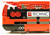 Not at all pure LEGO, but after a while I gave up trying to emulate a real sewing machine mechanism, and just went "embellishing" a real machine. Therefore, this is more of an "NXT-assisted" embroidery, than a pure solution. It's still a rather rough prototype, but it has proven the concept as worth the R&D. The X-Y fabric movements are simple - I've had much more trouble motorizing the handwheel (absolutely no grip, and occasionally huge torque required). Needle movements are imported from a program EmbroiderModder. Finally, some embroidered Classic Space, Technic and NXT logos for my bags and blank baseball caps :). A bit of extra text is here, and a YouTube video . Result that came out of the prototype after about 30 minutes of work... (the rusty old look is intentional - it can be avoided by using top and bottom threads of identical colours, rather than white & brown).
 -
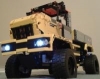 Hi. it's been a long time since last moc. on account of me moving. however i have been working on a articulated truck inspired by the Uniknick. like this one: Here it is: the model features (at the moment): - XL-motor for steering. - 2 x NXT motors for drive. Features i would like to implement: - front and rear hitch. - winch. i also mean to build a unimog u4000 or 402 cab for it. however i am not too good at building those sorts of things. i hope you can help me there. Here is the LDD file: http://www.brickshel...thout_motor.lxf Enjoy! Will upload more pictures to my brickshelf soon. http://www.brickshel...gi?m=KopMaister
 -
 Hello everyone. Who can help me get a set of hardware developer kit (schemas) for Lego NXT which was released in 2007 (8547) and was produced until release the EV3 I have found only versions before 2007 (9797) thanks
 -
Lego doesn't support a message protocol that is interchangeable between the NXT and EV3 brick. To overcome that problem, I have written a small program in C# to make the translation between the two different bricks. It works fine, but you always need a PC in between. At our blog (see https://siouxnetontr...pc-application/), I have written an article with a completely different solution, namely a 'motor communication protocol'. Enjoy. /Hans
-
 Hi there, Click here to download the building instructions on my website! It has been a while since my last GBC. But I have made a new one with new modules in it;) Click here to watch the video on my website with more information etc.: Here's some information about the LEGO GBC 8. To download the building instructions and watch the pictures, please visit my website: http://pv-productions.com/lego-gbc-8/ This time I used over 2000 LEGO pieces. I used 2 XL motors. One for all the modules and one for the airpump. I also used the LEGO NXT to control the LEGO GBC with your smartphone, so you can wireless turn it off and on again. You can also control the GBC with a mechanical switch. I also used the LEGO NXT for measuring data for more details. So now you can see the balls that have passed by, the average amount of balls per second and a clock to see how long the GBC is running. The mechanisms and functions, which I used, do not all have names. So I named them again by function. 1. Stop-go mechanism 1: Stops balls and let them go by at the right time. 2. Sinusoid: Moves the balls by making a sinusoid motion. 3. Stop-go mechanism 2: Stops balls and let them go by at the right time. 4. Elevator: Lifts the balls to a higher level. Every time 3 balls can fit in the cabin. 5. Bridge: Leads the balls of yellow tower to the blue tower. When the elevator(4.) is down the bridge will go up and when the elevator is up the bridge is down. 6. Stop-go mechanism 3: Stops balls and let them go by at the right time. 7. Vertical pushers: Pushes the balls in a vertical way up. 8. Color sensor: takes measurements of the balls. 9. Ball pump: Pumps every time one ball. A new ball takes a place beneath another ball and then pushes them up. 10. Android app: Controls the LEGO GBC Website: http://pv-productions.com/ Facebook: https://www.facebook...206638589482664 Youtube: http://www.youtube.c...op?feature=mhee Support site: http://lego.cuusoo.c...deas/view/51642
 -
Hi there, I previously posted the LEGO GBC 8 but now, after a week, the supportpage of the project is finally published. So, support the project if you want. Thanks. Click here to download the building instructions on my website! Click here to watch the video on my website with more information about mechanisms, programms, buildinginstructions, music I used, etc etc : Here's some information about the LEGO GBC 8. To download the building instructions and watch the pictures, please visit my website: http://pv-productions.com/lego-gbc-8/ Bron: Geek.com This is not GBC builder Philip Verbeek’s first outing with the concept — he’s on his 8th GBC build. Some of the past ones have included ball launchers, ramps, elevators, grabbing claws, and more. This time Verbeek has gone for a very ambitious build consisting of elevators, moving ramps, and a crazy undulating bridge. He’s also incorporated Lego NXT that allows him to track data about system performance and control the whole thing with an Android app. This new GBC consists of about 2,000 pieces, which is fewer than some previous builds. The contraption is powered by 2 XL Legomotors — one for all the modules, and one for the airpump. The mechanical energy from the motor is transmitted to most of the modules via gears or a network of strings woven through the blocks. Possibly the coolest aspect of this GBC is the Sinusoid ramp at the beginning. Watching it undulate while suspended by a network of strings its kind of mind boggling. It must have taken a good long time to get it timed correctly. Verbeek has also been kind enough to give us a walkthrough of the design. You can follow along with the gallery above to see each module up close. Stop-go mechanism 1: Stops balls and let them go by at the right time. Sinusoid: Moves the balls by making a sinusoid motion. Stop-go mechanism 2: Stops balls and let them go by at the right time. Elevator: Lifts the balls to a higher level. Every time 3 balls can fit in the cabin. Bridge: Leads the balls of yellow tower to the blue tower. When the elevator is down the bridge will go up and when the elevator is up the bridge is down. Stop-go mechanism 3: Stops balls and let them go by at the right time. Vertical pushers: Pushes the balls in a vertical way up. Color sensor: takes measurements of the balls. Ball pump: Pumps every time one ball. A new ball takes a place beneath another ball and then pushes them up. Android app: Controls the LEGO GBC. If you think you have the time and patience to assemble your own GBC with near-clockwork precision, Verbeek has made the plans available to download. It’s also on Lego’s Cuusoo page, if you think it’s worth supporting. Maybe Lego will finally make one of the GBCs a reality? You can also track Verbeek’s projects on Facebook and his YouTube channel. Website: http://pv-productions.com/ Facebook: https://www.facebook...206638589482664 Youtube: http://www.youtube.c...op?feature=mhee Support site: http://lego.cuusoo.c...deas/view/51642