
D3K
-
Posts
1,317 -
Joined
-
Last visited
Content Type
Profiles
Forums
Gallery
Everything posted by D3K
-
 Hi! Sorry if this has been asked and explained before, I tried googling and searching for help, but honestly I wasn't quite sure how to phrase my query.. I am currently making instructions of a truck MOC, and it turns out to be longer than the width of the page. As I see, it, there are two solutions to my problem: 1. Widen the page. This is easy, but I don't want my entire instructions to be in landscape mode, as the first half of it easily fits on a page in portrait mode. Needless to say; I can't seem to figure out how to make landscape mode take effect at a given step, and then last from there on out. 2. (And this is what I would concider my best solution in the current situation) Move part of the model "out of the frame". What I mean here, is, if I am focusing on building for example the front of the truck, there is no need to have the rear half in the frame. As always, pictures speak louder than words, so I'll show. What it's like: What I want it to be like: And here is the problem obviously: the right side front of the truck (that was initially outside the page) is not there. The parts "hanging out" outside the page now are not necessary to be shown in this step. What I'm wondering is; is there a command you have to use to make this happen? Also; is there a command to make a certain step in landscape mode whereas the rest of the instructions are in portrait mode? Any help would be greatly appreciated, even if it is just a link to a tutorial explaining it (as I'm sure there is, as there are several of the LDraw tutorials I haven't yet read)
 -
Still getting a little disappointed every time there is an update, and there are still no L or Servo motors!
-
Hmm, that might not be a bad idea! I am also thinking of a crane of Palfinger type (similar to the one on 8258), often seen on these kind of trucks behind the cab, maybe coupled with a cargo space behind it? Thanks! And regarding the diff; in the Swingloader it was more of a necessity, as there was some grinding of the 16 tooth gears toward the small LAs This model on the other hand, works perfectly fine with an unmodified diff.. I just wanted to see how a 6WD truck like this performed when put to the test, that's why I modified the diff And it performed very well actually, up until the u-joint broke, I had just one crack from a gear somewhere (probably one of the axle diffs) And making the a "base model" with several possible attachments could work actually! That way I could release the chassis first, and then release more instructions as I make different attachments, showing what modifications need to be done to the chassis itself along with how to build the equipment
-
Small update: I came up with a solution for the differential problem I mentioned in the last post. It is simply impossible (literally) to have the desired strength in the desired space with a lockable diff using legal techniques, the 4L diff is just too soft as it is. So I took one of my old ones, removed the small pin for the spider gear, made two small holes and pushed a 4L bar (cut to 3L) through it with two spider gears, like this: Thereby making it infinitely stronger. As I soon found out, the weakest link is now something more traditional: And that was actually inside the torque tube part for the 2nd axle! I'm still playing around with what to put on the back.. I concidered a standard tipper, something like this: (That's the one from my last dump truck, which isn't quite to scale, but I used it to test geometries and whatnot. Then there was the previously mentioned logging attachment in 8110 style: And yesterday I started playing with the idea of a hook lift. I made a pretty nifty mechanism to change from tipping to unloading, if you can manage to understand it from the following two images: Loading/unloading container mode: Tipping/dumping mode: It works by rotating the 9L axle roughly 1/4 of a revolution. In the first picture, you can see the 4L axles attached to the rearmost set of pulleywheels with a set of #1 angle connectors, are pushed through the 2x4 bent liftarms attached to the chassis. At the same time, the front pulleywheels pull out the 3L axles, thereby disengaging the front part of the hook lift bed. In the second picture, it's in the opposite setting, rear 4L axles disengaged from the 2x4 bent liftarms, and the forward 3L axles engaging the front of the hook lift bed, thereby making a rigid platform all the way to the back. Still a lot to figure out regarding the final model. I have for instance removed the ability to engage/disengage the diff lock remotely, thereby making more room for other functions. Higher resolution pictures, as well as WIP photos and some renders can be found in this bricksafe folder.
-
[HELP] Towball and Ball Parts
D3K replied to aol000xw's topic in LEGO Technic, Mindstorms, Model Team and Scale Modeling
The 2907 Technic Ball With Grooves is also used in the swashplates of helicopters 8412 and 8856, where it functions in more or less the same way as in the 8880 hubs, except to allow the rotor to be tilted on two axis. The 2736 Axle Towball fits into any part with the female towball socket, for instance this part , and probably a whole lot more. -
It looks soooo good! Can't wait to see the details!
-
Not a bad idea that.. I have an LDD that I can modify to have the same "space" in the rear as the MLcad model, so that people can see what they will be able to fit in there. Currently I have a dual pump compressor installed (for a rear logging attachment, heavily modified from the one off 8110), with room to spare. Also I am concidering removing, or at the very least redesigning, the motor for the RC diff lock, as it doesn't work 100 % reliably (motor turns back after it stalls when engaging or disengaging the diff lock. Thought I fixed it by adding some backlash (8 tooth gears), but apparrently not quite). Another thing is the central differential (4L 24z + 16z type), that seems to be pretty weak. The entire geartrain is very solid and well reinforced, but I have a lot of gear crunching inside the diff when I hit an obstacle. Ideas on this? Update: (clickable for high res)
-
Been doing some more MLcad'ing, and have finished the bigger part of the chassis, stepped and everything, ready to be made instructions of. I still need to figure out a nice way to fill in the space between the front and rear axles on both sides, as well as find out what to put on top of it. I am concidering releasing instructions for the chassis + cabin, and leave the back open for modding by those interested.. Thoughts on this approach? This is more or less the state of the physical model at this point as well
-
Oooo, looking forward to this! Can you reveal what shipyard you did this for?
-
Perhaps the prelim picture was of the B-model!
-
Thanks for the reply! I run Windows 7 64 bit on a fairly decent laptop (core i7 quad, 8 GB RAM and a 2 GB Nvidia graphics card), so hardware should be OK. I did a hard reinstall of Windows since the Swingloader MkII, but I remember having the same problem there. As it is now, this is the most annoying and time consuming part of the entire instruction making process. I will try some different things to see what I find out EDIT: Installing Ldglite, and using that as the preferred renderer seems to solve my problem. Rendering of the steps seem infinitely faster!
-
I never got SR3D Builder to work on my computer, which is kinda annoying. But I am liking MLCad more and more! I also finally got POV Ray figured out, so I'll show you my first self made render, where you can also see the progress of the model instructions: I have also finished modelling the cabin, but that's not coming on just yet EDIT: Is it normal for LPub to take 15-20 seconds to render each step? I'm just wondering, as the render above took maybe 5 seconds tops, and it looks better than the ones coming out of LPub. That being said, I have no clue as to how this actually works, and which parameters are concidered, hence me asking
-
General Part Discussion
D3K replied to Polo-Freak's topic in LEGO Technic, Mindstorms, Model Team and Scale Modeling
The only two Technic sets that come to mind that used similar Bionicle pieces, are the 8421 Mobile Crane and the 8420 Street bike. They used these parts respectively: (in black) and -
I too am a bit disappointed at how the Endurance Racer 42039 turned out, as opposed to the preliminary picture. I can see how they might have to make some aestethic compromises for the model to be playable (without being broken) by children, but several positive aspects of the prelim model seem like they could have been adopted into the final model for a better result. I particularly don't like the new splitter and front lights that much on the new model. Also, just by using white flex axles on the cockpit, it would have been better defined and also looked a lot better I think. The Motorcycle 42036 is pretty much as expected; it looks like earlier Technic motorcycles more or less. Odd colour choice though.. It definitely looks a lot better with the stickers applied! The Snow Tracker 42038 looks pretty awesome, and is something completely new! Hats off for the Technic Team for getting this model through, can't wait to see what it's like. Also, it's great they have used such a wide range of colours across the models!
-
This is the state of the MLcad modelling and instruction making process as of right now: In the process, I built a V8 in MLcad, which proved to take a lot of time. So if anyone is interested and don't want to spend a lot of time, I have a finished .ldr V8 that you can download here. Looks like this:
-
9: 10 3: 6 1: 4 10: 3 5: 2 8: 1 Difficult choices, all entries are unique and very well made!
-
Also something unique! I'd try to use some flat panels for the "walls" in the tower though.. Seeing as it is 13 studs wide, you should be able to fit flat 5x11 panels on all sides (except the rear), or at least the front!
-
42035 Panels
D3K replied to Richard Dower's topic in LEGO Technic, Mindstorms, Model Team and Scale Modeling
You probably could, by placing two of the left, or two of the right, together -
[MOC] Volvo L250G Wheel Loader
D3K replied to M_longer's topic in LEGO Technic, Mindstorms, Model Team and Scale Modeling
That is truly a fantastic MOC! Looks awesome, can't believe you managed that in such a short time! -
You can use File/Export BOM to get a parts list in LDD, or you can check out Rebrickable for this MOC.. There you can make an account, and add all your sets/parts, and it will tell you which parts you're missing. Building from an LDD file is not ideal, especially if you've never used the software before. Taking that into concideration, you might be better off building Han's 10x4 dump truck as he's made proper instructions, although that one is significantly longer, and of course you'll need to dish out the 10€ for the instructions. That model also uses some rather rare/expensive parts
-
I suppose it's more profitable for the creative minds to build, rather than to tear apart Taking apart a large Technic set can take some time, more so if you are to sort the parts. Dismantling a MOC contributes very little to the creative process I would imagine, so I suppose them using their time to create, makes up for the loss of materials
-
Hi! Yes, the dump truck I actually finished, it ended up looking like this: There is a separate topic here, where you can find additional photos and information. I also have a bricksafe folder with some WIP photos of it. I didn't make full isntructions for it, but I have the finished model in LDD, that you can download by clicking here. It should be fully buildable from that file, however I suggest you start with the front axle and make your way from there, if you decide to build it. Feel free to PM me any questions you may have regarding the build Building dense is well and good, until you decide you should have some additional features!
-
The wheeled excavator has been dismantled long ago, didn't get much farther than what you see in the LDD picture you mentioned. Maybe I'll give it another shot in the future! As for the current project, here are some pictures (clickable for large resolution): Early version (yesterday) of the front axle and misc. Here I was going to use a PF-Servo for steering, but it created to much slack and backlash. I rather opted for a PF-M motor wormdriving the steering axle. Here is what it looks like standing on my desk tonight. First of two rear axles added. The M-motor on top is for locking the central diff between front axle and rear axles. Here you can see the front live axle assembly I showed you yesterday, and also why it had to be so low. I wanted the V8 as low as possible, so I couldn't have a too high profile on the front axle The model is going to be yet another truck, with some similarities to my last PF Dump Truck. This will however be 6x6 driven, and be more of an all-terrain/offroad truck. Still haven't decided what to put behind the cab, was concidering something modular
-
Technic General Discussion
D3K replied to Jim's topic in LEGO Technic, Mindstorms, Model Team and Scale Modeling
I started tinkering with a Deltawing MOC, but soon left it for something else. A good MOC of one is something I really would like to see though! Fascinating piece of engineering! -
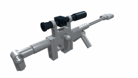
I need a driven, steered live axle, with a low profile, and this is the result (after a lot if trial and error).. But it probably makes more sense when you see it together with the rest of the model:-)