
gyenesvi
-
Posts
2,396 -
Joined
-
Last visited
Content Type
Profiles
Forums
Gallery
Everything posted by gyenesvi
-
General Part Discussion
gyenesvi replied to Polo-Freak's topic in LEGO Technic, Mindstorms, Model Team and Scale Modeling
Isn't that just implied by the basic laws of physics? -
So what's wrong with the 5L liftarm that you put there? Or you could just attach it rotated to face the rack. Or you could just use 5L thin liftarms with axle hole ends, that should be easier to attach to the vertical assembly with longer axles. Or just 4L thin liftarms if the 5L is in the way at the top. Or I think this piece will fit right in there :) Just put it with the axle hole end downwards so that the edge does not get caught up in the 7L flip-flop beam. By the way, I can see that you are using a Cada 7L flip-flop beam? Use a proper Lego one in this case!!! The difference is that the Lego one does not have those U shaped cutouts with all those edges, so it won't get caught up in all nearby edges that you put there as limiters! The Cada ones are bad in this respect.
-
I think this should work, takes roughly the same amount of space in the middle as your current version, but it has a straight rack between the links. Note the 7L liftarm under the rack, to allow it to sit and slide on the beam underneath. The extension gets a bit close to the tires, but as I checked it does not seem to rub them.
-
Actually, that sounds like a really good solution, because then the links would be 1 stud higher and forward, and they could be directly connected into the 7L flip-flip beam, or even the steering rack itself if it was moved 1 stud back, in case the engine mounting is revised (hopefully there would be enough space above the links, because the suspension does not move too much up I guess).
-
That's some impressive stuff! And I thought that my 120€ FlySky transmitter was a one of the better ones.. I didn't know other more advanced ones allow for channel remapping, but it makes a lot of sense actually. Indeed, that would make things easier on the receiver end. That's a pity, but I understand.
-
Thanks! Here is some progress on the bodywork. When I saw in @Appie's video that the fender parts of the Icons Defender are available in white, and looked it up on Bricklink, I realized that they are also available in black, which are just ideal as they go well with many colors, I immediately decided that I need to get some and build a Defender with them because they seemed ideal for 56mm wheels :) Also, it's something that the Traxxas TRX4M platform comes with as a body option, so it's fun to replicate it in lego form. So here's the design I came up with, a pickup version that I have been planning for a while. It is meant to be detachable as a single piece, just like in RC models. I have built it partially (need to buy parts in the right color), and started testing it. The trickiest part is of course the front section, being able to make the wheel wells large enough so that the tires don't catch up in the edges. Unfortunately, with the weight of the body, the camber of the front wheels get more emphasized, and there's more play in the wheels, so it gets harder, more space is needed for the wheel. I went a long way trying to make the front face as thin as possible while not pushing it too much forward to keep the proportions more or less. Also, I tried to mount the fender parts as firmly as possible. Here's a close-up of the wheel well. It's all supported from the top panels, and it actually came out sturdy enough. The face has a bunch of half stud offsets for the grille and lights, which are quite well possible with tiles and plates. Another area where I resorted to system plates and tiles is the wedged hood top / bulge, I think this is a good and simple solution. I managed to make a nice technic top (it is solid, and can be grabbed by the roof). Here's how it would look on the chassis. By the way, to make this possible, I had to make the chassis one stud longer. Now it's the same size as the new Bronco (also, I could have just used the Bronco's body on this chassis, but that would have been too easy). Furthermore, I added some bed sides to the chassis where the battery will be placed (I could not attach that part to the bodywork). You can also see the mounting points for the body, maybe I'll add two more to the tail as well (for now it would just rest on the chassis).
-
I think that's good enough. Okay, I understand, that sounds good. Yes, I was curious about things like these. I know that there are off-the shelf components even for basic motor controllers, like H-bridges used in Lego PF receivers. I just wondered if you used things like that or some microcontroller, or an entire programming board. What code did you need to write? But this is a bummer, it invalidates the whole concept for my use case. The servo ports are one of the most useful things for me when going with RC transmitters, as GeekServos are cheap, small, fast, precise and powerful, while Lego PF servos are rare, expensive, bulky and slow/imprecise. And on RC transmitters, steering is always channel 1, and channel 3 and 4 are two/three position switches also useful for gearboxes, for which servos are also best to be used. So with that I am loosing exactly what RC transmitters are best for. Sure, channel 5 and 6 could be used (continuously variable knobs), but those have less use cases for cars I guess. Wouldn't it be possible to output all receiver channels to preserve the servo possibility for channels 1-4 as well? Since that does not need any extra circuitry for RC servos, they can be attached directly. That would broaden the utility of this little box by a large margin I think. For me it's not so much about speed and power, but more about having good control, both in terms of speed control and steering control. This is why nowadays I am experimenting with brushless motors / ESCs, along with GeekServos. The reason I am asking all these questions is because I would also be interested in putting together something of an integrated solution for my use case, preferably from some existing components. For example I have small AFHDS2 capable 4-channel receiver, it would be good to integrate it onto one board with an ESC (maybe something AM32 based) to reduce wiring. Sure, no problem, thanks! Also, one practical detail. I like the XT30 connection to the battery, but batteries often have a very short output cable. So with this solution, it would often require an extension cable between the box and the battery, depending on their placement in the model. Maybe it would be better to have that XT30 connector on a 10cm wire, coming out from the box, eliminating the need for an extension cable in most cases. That would also free up some area on the top of the box for additional channel outputs ;)
-
It's interesting to see this, even in retrospect, since a nice solution has been worked out. When the 4L link came out, I was wondering how they would solve this problem of going around the differential, which is always an issue due to lack of parts in the right sizes; this is exactly where having proper part selection that work well with each other matters. A 9L steering rack could have provided a fairly straightforward solution (not just here but in some other sets as well), but they continue to hack around with those 2 existing rack lengths, often building convoluted steering assemblies, and here is the result.. And the stiffest solution would need a 9L rack and the 4L links with perpendicular holes..
-
Interesting to see all this progress! The form factor looks really nice, and the functionality is promising! Are the PF ports reversible? Or are you just counting on the transmitter to be able to do that? Are the PF ports controlled separately from the servo ports, or are the signals duplicated to them? Can this be controlled with a pistol controller that only has 4 channels? You say that AFHDS3 and AFHDS2A receivers can be used. So is the receiver not contain inside? Though later you say that there's one box that has the receiver inside.. So what's the plan with that? I have a FlySky FS GT5 transmitter (pistol), which has 6 channels and uses AFHDS2A. Can that be used? You say that you developed your own PCB with software, that's really interesting. So does that have a custom microcontroller and motor controllers? Is the receiver separate, and connected to the main PCB? Is it possible to get a peek inside the box? :)
-
Actually if you have an electronics tool to measure voltage (digital multimeter), it is possible to measure each cell of the battery separately on the charging cable, it's a bit tricky though, you may look it up in google. It seems that they could revive the 3rd cell of my battery, probably it was over discharged for some reason (maybe because it was brand new and should have charged it before use), I can pick it up tomorrow and see how it works. So far I was satisfied with my other Tattu battery, and it's not too expensive either. Thanks, glad you like it! I guess counter rotating shafts would require more space, not really possible in this small scale, but good idea!
-
[MOC] TRX-4 1:10 Lego version
gyenesvi replied to Krxlion's topic in LEGO Technic, Mindstorms, Model Team and Scale Modeling
Thanks for clarification, the missing piece of info for me was the existence of the open category :) -
[MOC] TRX-4 1:10 Lego version
gyenesvi replied to Krxlion's topic in LEGO Technic, Mindstorms, Model Team and Scale Modeling
Those rules make sense, interesting to see that the scale is so small, I thought those 96mm tires would result in about 1:10 scale. However, what puzzles me more is that if original Lego motors are required, then how was the brushless setup of @Krxlion competing here? Or was it a version modified to have Lego drive motor? And then is it allowed to have RC control electronics, like ESC, battery, transmitter/receiver? I guess that's required to control the GeekServo as well. -
I have recently discovered that it is possible to embed a short video that is hosted on Bricksafe the same way as embedding an image, which is pretty good. However, I have been wondering how it is supposed to be used / working. In my experience, what happens is that it's embedded in an autoplay, silent way. That means when I embed more than one video, they will both autoplay, and there's no way to stop them, and also to hear the sound we need to open them in a separate page, the possibility of which is not obvious. All the autoplay videos can be a bit distracting, but the even bigger problem is that in quite some cases it won't embed automatically (this happens for images too and not sure if there's a way to force embedding of a link) or when I open the page it won't display (even though it did display a few minutes before), and not sure what it depends on, probably internet throughput, which may be limited by Bricksafe's side as well, but I guess the more embedded videos want to autoplay at the same time the worse it gets. I was wondering if it would be better to embed them without autoplay, and allowing the user to start them as needed, with sound. Are these embedded with the HTML video tag? In that case it allows embedding with controls instead of autoplay. Could this be a choice when embedding a video in the post?
-
Indeed, I also like to go small scale and test the limits of how much suspensions can be miniaturized :) Thanks, glad you like it! I actually have a 450 mAh version of the same Tattu 3S battery you see on the image. However, I have never really used it, and when I started using it to test this motor (yet with no load), it was working okay initially, but after a few minutes, one of the cells lost all charge, and now it does not even charge back with the LiPo charger, but the other two cells work, and now it's like a 2S.. I took it back to the shop and they said they might be able to revive that one cell with slow charging, now I am waiting for that.. Do you have any other good small 3S that you'd say is worth buying? I am thinking about using them, mainly want to experiment with portal axles (you can read about my ideas in another thread I made about those). But for now, I don't want to go too far with custom axles and bearings and gears everywhere, I think for slower models they are not needed yet. Well who knows, it would be good to see the limits of those gears. I guess it is more difficult without the planetary reduction, the mounting points are 12 mm apart, so you need some custom part there anyway, and then the shaft is 2mm D shaped, so attaching a gear that can be used in connection with lego could be more difficult. And then you'd still need some down-gearing, but I guess you have figured a solution to that problem out already. Curious what comes out of it!
-
[MOC] TRX-4 1:10 Lego version
gyenesvi replied to Krxlion's topic in LEGO Technic, Mindstorms, Model Team and Scale Modeling
That's a really nice even, love all those big trucks :) What were the rules? Was there no limitation on the form, such as only trucks? Was everything allowed in terms of electronics? I didn't think there would be an event where brushless motors are allowed :) Agree that ground clearance is the most important. Also, for such competition, open or lockable differential is pointless. Just close them all permanently, and you'll simplify things and even gain space as regular gears can be smaller than diffs. About gearbox, I'd say that even if you have it, 2 speeds are enough; you only need the two extremes really. And that simplifies the drivetrain a lot too. Also, for trial, live axle also at the front gives better articulation. I'd only use IFS for fast models. -
Good to hear that this looks great even in comparison, and sorry to hear you burned yours! But I definitely agree you should try this one. Also, I'm considering buying its bigger brother too, the Fat Viper, a 28x19 mm variant for bigger models.. :D Yeah, in sinusoidal startup mode the motor is really silent! Agree this could even move bigger models, like 62-68 mm tires. For 1:10 scale on 80 mm tires, I'd go for the bigger one, or the 2435 SurpassHobby motor. Hope that one won't burn down this ESC :D It is supposed to handle 25 A continuously and 60 A peak, while the 2435 motor description says it takes max 22 A, so it should be okay I guess.
-
Thanks, indeed, I agree with you about the weight on the front. The bigger problem however is the steering motor, moving that would be more of an issue. Maybe something can be done at a larger scale. Also, for this scale I actually plan to use a smaller battery. Thank you! Yeah, I have been eyeing on those too, but for now I don't want to get carried away too much with custom parts yet, only electronics and tires. I guess that will open another rabbit hole :) Here are some short videos I made to showcase how it works. First, slow speed climbing: https://bricksafe.com/files/gyenesvi/private/small-scale-brushless-chassis/DJI_20250908_132226_167_video.MOV Then some high speed driving, it's only almost full speed towards the end because of the small space I had.. but it's surprisingly controllable, and the steering radius is great too! https://bricksafe.com/files/gyenesvi/private/small-scale-brushless-chassis/IMG_7970.MOV
-
Thanks! Sure there's a little camber, but it's really nothing major, much better than I expected, and the goal here is definitely to maximize ground clearance, so I don't plan to add anything to the bottom.
-
Anything with proportional control and a customizable app can have such features; end point adjustment can simply be achieved by setting the max output percentage. The Buwizz app has customizable output curves, where the mid point can also be shifted, and even non-linear output response can be achieved (even though the interface is pretty cumbersome and hard to set accurately). However, I realized that there might be a small issue, if you want it to work both for PF receiver and with app control / adjustability. The PF receiver would require to have the end points to be at 90 degrees in both directions to work as expected, like a PF servo. However, to make it flexibly adjustable from an app, the default end points corresponding to 100% output should be more than 90 degrees, say 180 degrees in both directions, and then 50% would mean 90 degree rotation. This would be required to be able to set max angles to more than 90 degrees, and also when trimming is applied and the center point is shifted, then even with 90 degree rotation, one of the end points would need to fall out of the +/- 90 degree range. So, one option is to define the base range to be 180 degrees, then it will work adjustably with app control, but not as expected with PF receiver. It could be okay, because usage with the PF receiver and normal PF controller is actually pointless, you'd loose the proportional control anyway (unless used with a train remote?), which is the key advantage of using a precise servo anyway. So I'd actually say that this is not a bad option, not much is lost. The other option would be to make a two-way switch on the board to only be able to select between 90 and 180 degree max range, 90 degree to be used with PF receiver, and 180 degree to be used with app control. That sounds much simpler than full end point adjustment and trimming capability, no?
-
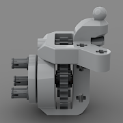
Hi! This thread is meant to document my first build using a custom brushless motor. If you follow the "Brushless Motors in Lego" thread you may have seen the motor design, but I give a quick summary here as well. Apart from the brushless drive motor, I am using a GeekServo for steering, and control them with an RC pistol transmitter/receiver. So lately I started experimenting with 3d printing lego compatible mounts for brushless motors. I bought a small Injora Purple Viper motor with a corresponding ESC to control it; they come in a package for about 50 Eur, that includes a 11T gear and mounting screws as well. The idea was to make a motor that fits into a 3x3x6 space including a two stage planetary reduction, which is taken out from a 3rd party PF M motor (costs about 3 Eur on AliExpress). Apart from these parts, only the 3d printed housing is needed. The result looks like this, more info in this thread. The key to this design is that it is possible to run a driveshaft right below the motor, furthermore, there's even space for heavy duty CV joints, as the motor itself is narrower: There are two obvious gearing options, 16:16 and 20:12. I checked Injora's transmissions that are applied with these motors, and they also come in two options, the "normal" provides a 1:13 down-gearing, and the "underdrive" version provide a 1:24 ratio. Since the two stage planetary reduction from the M motor is about a 1:24 down-gearing, applying a 16:16 on the output results in exactly the "underdrive" ratio, while applying the 20:12 up-gearing on the output results in a 1:14.5 total down-gearing, which is roughly the same as the "normal" ratio with the Injora transmission, so there's a pretty good speed correspondence here with RC parts. By the way, these Injora parts are designed to be a drop in replacement for TRX4M Traxxas models. So this was the starting point for my chassis, and I wanted to see first how small a 4x4 off-roader I can build, aiming for 56mm tires and two live axles. I also happened to have some soft and sticky Injora tires too that I wanted to try for a couple of years now.. For the front axle, I have been wanting to test this tricky wheel mount technique I have seen used by some builders around here, making it possible to use heavy duty CV joints at this small scale (9-wide axle between the pivots), combined with my linkage based steering techniques I used before: This is a fairly slim and dense axle for what it achieves, quite happy with it, however it misses two upper links, and the panhard rod also proved to be a bit far away, so it became a bit wobbly under the power of the servo, so I had to use other tricks to make the axle stable.. For the rear axle, my aim was to make it as flat as possible to be able to run beams right above it without obscuring the trunk space. It is an often used negative caster (torque tube suspension) setup with only one CV joint and two links and a panhard rod for stabilization. The springs are also mounted on the back to be able to lower them and so that they don't protrude to the trunk. A chassis that holds all these components together came out quite slim as well, I'm really happy that it actually looks somewhat like real RC chassis platforms! The servo is mounted fairly low at the front, and there's just enough clearance for the drivetrain even when the axle is articulated. Another key element is that the servo is in between the springs, and right behind the front axle's cross beam, and it actually stabilizes the axle, not allowing it to move too much sideways or tilt forward/backward (just enough to let it articulate freely). These limiters together with the panhard rod make the front axle stable enough so that the servo does not pull it sideways when steering, resulting in a really good steering response and a quite high steering angle! As you can see, there's plenty of space left for building internals / body and also for placing a battery and ESC/receiver to the trunk. For now, I have mounted these items with tacks onto the chassis for testing, it looks like this: As for performance, I don't yet have a video, but I am pretty amazed by this little thing. Speed control is just very smooth at startup, and with those RC tires, it can climb steep ledges with such confidence that I never thought possible with lego parts. First I tried the 16:16 gearing, but I though it does have enough torque for the faster one, so now I swapped it to 20:12, which has the advantage that the gear below sticks out less, and it does not get caught up so much from the bottom. Also, this way the top speed is very good, like something with a buggy motor (or two), but with much better speed control (and steering). Will make a test video soon, just need to practise filming while driving.. :) And the next step will be: building a bodywork; I'm thinking of a small Jeep, like a CJ or a Suzuki Samurai, but ideas are welcome printing some casing for the battery / ESC / receiver to enhance their placement / cable management (in the trunk)
-
Did MK just copy the Buwizz motors as they are, without even changing the label? That would be soooo lame..
-
Version 2 of my motor housing! :) As I started to build, I realized that it would be good if the sideways mounting holes would be vertically in the middle of the motor, because then it would be possible to hold it between two beams that are just the right height for dropping the output shaft right under the motor with one gear mesh; the simplest ever driveshaft (see below). So I designed another housing, where I could add pinholes in a row, and even round off the whole thing, and change the assembly so that it requires less screws, holding the back panel from the side. I also removed the back cover to prevent the motor from overheating. This version looks like this, as slim as it could get: The first pinholes (towards the face) are full stud deep, while the rear ones are only inverse studs for half pins. The new mounting points hold the whole 3L front section firmly, so there is no need for stabilization on the back. At the same time, it can be assembled using only the screws that come with the motor, and it is easy to disassemble and assemble again multiple times (the wear of the screw holes does not matter, because it is actually the head of the screw that holds the back wall). Another advantage is that now the wire can come out in a diagonal, allowing the motor to be tilted 90 degrees and mounted from the front without the wire interfering with the beam that runs next to it. The motor can also be mounted so that the wire comes out on the top, if needed. This is how it looks in more detail: Of course, it is possible to combine the two designs, and make a square version that has more mounting holes than the first version had: Now as for building, this is how the most compact 4WD off-roader driveshaft for live axles could look like (two gear ratios are possible): I have built this into a small scale 4x4 chassis and the performance is just great, super smooth control, great top speed! I guess I'll just open a new WIP topic for showcasing it!
-
[APP] BrickController2
gyenesvi replied to imurvai's topic in LEGO Technic, Mindstorms, Model Team and Scale Modeling
Yes, that is possible, you have to create the same control action (same button event) 4 times, and hook up one separate output for each one, with the same control parameter, except for maybe the direction, depending on how you built your model, whether the motors need to spin in the same direction or opposite. -
Good to hear that there's progress and there are prototypes already! Curious about the prototype car! However, I am not sure it's so important to add trimming and end point adjustment, especially if it comes at the cost of getting bigger. For one, if used with the PF system alone, it's already much better than the PF servo (smaller, faster, stronger), which also does not have those adjustment possibilities. However, when used with a Buwizz + app control (or even with PU hub + PyBricks if there was a version with PU plug), then both end point adjustment and trimming can be done from the controls software. This is the same way as in case of RC transmitters, the trimming and end point adjustment is in the transmitter. So why complicate it unnecessarily?
-
Thanks! The back section is completely optional, not necessary for functioning, so it can be left out to allow more cooling. However, there's a slight other problem with the back section: it cannot be taken apart without breaking off the mounting tabs (they kind of get jammed in the hole and rather break than slide out). Also, it is just in the way for the large head of the HD CV joint as I am building my 4WD off-roader.. So I might just do away with the back for now.