
Search the Community
Showing results for tags 'pneumatic'.
-
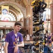 This topic is for pneumatic tips and tricks, how to use pneumatics and mocs including pneumatics or just general things about pneumatics. Ps mods if you feel this topic is not required feel free to remove. I just made this seeing there was no general discussion on pneumatics.
 -
 Hi everyone I need some help to troubleshoot an issue that I'm having with a Pneumatic Pump. It has a leak, but I don't think that it is the piston or the one-way valve. I think that there may be a tiny hole in the black casing. Please watch this short (2 min) video for details: Has anyone experienced a similar problem, or have a solution? I was thinking that I could use some glue (hot glue / super glue / two-part epoxy) to block the hole, but I didn't want it to seep in and block the air flow completely. I've had this pump for a few years, but I think this is the first time that I have actually used it. If this is a manufacturing defect, do you think Lego would replace it? Any advice would be appreciated. Thanks.
 -
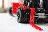 Hello, this is a WIP of my latest moc: a MAN TGS 8X8 leafspring suspended fully RC with autovalve compressor pump! Plus many other features and functions. It also features many attachments, like a Fassi F1950 XP crane fully RC using new pneumatic V2 system! It also has a dumping load bed, a front snow plow (this will be shown later on when completed! The idea is to use the cabin and chassis as a starting base to develop more mocs like the XXL version of the same truck, 3 axle, 4 axle, 5 axle. Functions: - 8X8 driver train driven by 1 L motor - Realistic steering system with levers (plus different angles between 1 and 2 axle) steered by an M motor - Pneumatic compressor with autovalve powered by an L motor - 2 IR receivers that controls the drive, steer, 1 pneumatic switches (in this case used for tipping the bed) and 1 more motor for extra function (in this case used to rotate the crane) More pics here: http://bricksafe.com/pages/TheItalianBrick/fassi-f1950-xp http://bricksafe.com/pages/TheItalianBrick/man-tgs-44.480-8x8 I'll progress I'll take more and better pics. Enjoy what I have so far! And this is the crane, it's also a WIP but so far I'm happy with the result!
 -
 Time for a dedicated topic as well. Link for high res image: https://mega.nz/#!qDQh2aZC!9L0SMGXuq9L_1oSgaaj20bn-H47tcH2jS8gCeEgJlFM This is the ultimate color barf that TLG has managed to produce: - Lime - Green - White - Yellow - Black - DBG - Red - Blue - Medium Azure - Reddish Brown Discoveries: - If you zoom into the cabin you can see a water bottle with a silver cap - There is a 6L towball link bar under the front row of wheels.
 -
 Hi everyone! Not long ago I finished my latest MOC. And today I finished the corresponding video. So it's time to show it here. Shortest description would be: Stewart platform for Ideas set 21306 „Yellow Submarine“. The longer description is: It's a MOC I built around the Ideas set. It's a fully working stewart platform powered by two pump compressor and controlled by two joysticks. Everything is working pure mechanically and with pneumatic. For better look I used system bricks for the control tower (with female naval engineer) and the housing of compressor and control center. Components: 1x PF L motor 1x PF M motor 1x PF LiPo 2x PF switches 6x Pneumatic V2 cylinder (small thin) 2x Pneumatic V2 pumps 6x Pneumatic Valves some PF cables Looking forward to reading your comments. Best jrx
 -
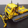
 Hello everybody, during this holidays I purchased the 42081 and decided to build it a little different. First, I made some minor changes in design, to look a little more similar to the "real" Zeux. I changed some color here and there; the yellow panels in the middle are different; the placement of the "02" adhesives is on the lower DBG panels instead of the upper ones. But the biggest MOD was to add the pneumatic system, with motorized pump, instead of manual LAs. The valves are located on the sides of the loader, 2 on the left and 2 on the right. There are 2 big cilinders (to rise the arm and the rear axle) and 2 medium (old) cilinders, to operate the bucket and the counterweight. Here you can see the last cilinder, the pump and the motor, located below the battery box: And here is a short video:
 -
 Hi, Can someone please tell me if there is a practical maximum hose length for a Lego pneumatic system? The application I have in mind is for ‘remote switching’ of a railway track point. The track point is ~1500mm from where I want the switch. I presume I would be best to use 3rd party hose at these lengths. I’ve tried to search for an answer, but nothing has turned up. Can anybody here help? thanks david edit: ps, I am probably going electrical, but just thought I’d consider a pneumatic solution, though it appears in any case parts for that may be difficult to source.
 -
Hello there! I ran into a small problem recently. I'm trying to synchronize a couple of pneumatic cylinders which are not connected directly to the same frame and they keep extend and retract at different speeds. The hoses are exactly the same length and the cylinders are from the same batch - they are not old+new. But even if I get the synchronization correctly then one of the cylinders does a harsh or abrupt action. For example when the pressure in the system is rising one cylinder starts to operate right away and the second cylinder is "stuck" until the pressure is high enough and it extends abruptly. I've spent couple of hours manually extending and retracting cylinders in order to make them work smoothly without success. Did you have such problem and if so - what was your solution?
-
 how do i steer pneumatics whit ev3 ?
 -
 Hi everyone, For the past year, I have been working on this MOC, making very slow progress mostly due to a lack of time. About a month ago, I finally reached the point where I considered it finished. It's not perfect and many things can be improved, but I am happy with the current state. Enough to finally make some pictures and a video. The MOC is based on the Manitou TMT 25S. It is a hydraulic forklift, one that hooks on back of trucks, but uses an unusual design. A picture from the original: It also combines some interesting hydraulic functions which I tried to carry over to my model. In the end, this is the list of functions I managed to implement: Manual steering, control placed at the back, behind the cabin - rear wheel goes 360 degree. Pneumatic compressor using an M motor and two pumps Electric switch to control the compressor Pneumatic functions for: Boom elevation Boom Extension Fork control Front outriggers Boom lateral adjustment Initially, my intent was to have an auto switch for the compressor. However, after many trials, I could not calibrate it properly so that enough pressure remained in the circuit to control all functions properly. The switch would not always return in position when the pressure was dropping, making some functions such as raising the boom unusable. So I replaced the assembly with a manual switch which can easily be controlled when air is required. To smooth out the functions, I used an air tank which is hidden below the control valves in the back. Overall, the functions are working well. The main issue is the control of the fork, which really needs better smoother valves to have finer control. Also, since it is pneumatic, It does not maintain its position when elevating or lowering the boom. I could not find a way to do that while keeping the boom extension which is required. So here are the video and pictures. I hope you enjoy it. More pictures are visible on the BrickSafe folder: https://bricksafe.com/pages/Minique85/manitou-tmt-25s
 -
After seeing @jwarner's excellent smalle crane and @Ludo Visser's WIP on a good looking undercarrage, I kept being reminded I still had one of these on my "to-do list". It's the last (I think) in what turned out to be a series for me of small versions of vehicles that are usally the big 4 "flagships" in Technic that return every couple of years. It features: - Boom lift by pneumatic cylinder - 1 stage boom extension - Rope (with old school 90's lock and also a hook from the 90's ) - 3 axle steering with different steering angle for the front wheels (bottom 12T bevel gear at the rear) - Working V4 (allthough a little out of sync, can fix that as soon as Lego actually makes parts to shift direction at this scale on 1 stud instead of 2 ) - Cabin tilt on the superstructure (through a worm gear controlled by 12T bevel on top) - Superstructure rotation (top 12T bevel gear at the back) - Outriggers (couldn't fit a central operating method so they are moved at the rear through the LBG crank shaft parts usually used for fake engines) Stuff I couldn't squeeze in no matter how hard I wanted to: - 2 stage boom extension (with 11L thin pneumatic cylinder). I tried, but with ropes in play I was looking at a 2 studs wide crane without a shell to give it ridigity, anything with 3 and 4 studs in width with the shell still felt very flimsy. And shortly after switching to a 1 stage boom with these 11x3 panels I really started to like that clean look on the crane vs the thin liftarm extravaganza I had in play earlier - A diff (or at least have the fake engine run in some form on both non-steering wheels). I barely managed to get 1 wheel driven. Had to use some ancient 90's Space Shuttle technique with a rubber band to get the stuff routed. I considered a blue clutch gear from the Chiron on the steering shaft, but besides that really killing my ground clearance it wouldn't fit up top thanks to the pneumatic cylinder. Why not leave the feature out? Can't do that when all the other mini's I made had fake engines. It was this or never getting finished pretty much - And as mentioned earlier: the outriggers being controlled by 1 knob. Couldn't route it to the rear, already crowded, the cabin in the front was blocked by steering angle of front wheels and crane up top. I am happy though that they at least can lock into place and lift the whole vehicle. And a couple of more images: Instead of messing with the length of the hubs on the 2 rear steering axles to get different steering angles, I shortened the front steering hubs by 1 stud to get a sharper angle with space lost in height (rear of the driver's cabin) but not in length. It's turning radius is pretty sweet, very small. Tried to get some details in the cabin, but they are missing half of their bottom seats thanks to the steering wheels. Also messed around a little with options to get the outriggers folded into the body as much as possible, not sticking out more than 1 stud up top and when extended looking at a decent angle. Hmmm, now that I am looking at this picture, perhaps I should swap the 4L thin levers for LBG or something to make the fake engine "pop" from the black chassis. Anywho, thanks for watching and reading.
-
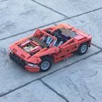 Hi, I have been trying and failing to make a small pneumatic car wth two cylinders that when air is pumped into an air tank, and a valve is released, the car will roll along a flat surface. Any ideas? Parts that I have: 2 (or 4) of the not-V2 style large cylinders 1 x Airtank 5 valves and 2 old style valves NOTE: I bought some small pumps, but they were all faulty.
 -
 Hello everyone. I would like to introduce my truck with excavator. It is loosely based on Tatra 815 with UDS 114 (universal finishing machine). The real thing looks like this: I really like this type of excavator, its main advantage is high mobility because it can even go on highway. It is mainly used on road building and terrain shaping. My goal was to make pneumaticly operated truck, preferably playable by kids. I started with some blueprints and decided to use 49,5mm wheels that set my scale to roughly 21,5:1. I wanted it to look like an older truck, with low cabin and boxy design. The model features: - HOG steering by spare wheel at the back of cabin - Openable doors with decent details in interier - Fake V4 engine that is connected to rear axles, each with differential and with shock absorbers (~1 stud travel distance) - Pendular unsprung front axle with ackerman steering (~3 studs travel distance) - Pneumatic stabilizers that are able to lift the whole truck - Pneumatic jib with manual extension from ~40 to 68 studs - Manually operated bucket with 360° rotation The above is a result of many compromises - like V4 engine instead of inline 6 etc. It is not possible to fit larger engine into this scale, I tried mini fake engine but I didn't liked how it looks. What is most satisfying for me is the front axle with ackerman steering and pivot point nearly in center of the wheel. That allowed me to build very nice fenders close to wheel. The wheel doesn't touch it even in full turn radius and fully compressed. The rear axles are by Efferman, he used this design in his Kenworth crane. I really like it. Enough talk, some pictures: IMGP4963 by Ivan Moc, on Flickr IMGP4964 by Ivan Moc, on Flickr IMGP4965 by Ivan Moc, on Flickr IMGP4966 by Ivan Moc, on Flickr IMGP4968 by Ivan Moc, on Flickr IMGP4969 by Ivan Moc, on Flickr IMGP4970 by Ivan Moc, on Flickr IMGP4971 by Ivan Moc, on Flickr IMGP4973 by Ivan Moc, on Flickr IMGP4974 by Ivan Moc, on Flickr The weight of the fully extended jib is pushing the thin pneumatic cylinders to their limit. I wanted to keep thin ones at all cost because they look much better. I have redid the jib like 15 times, ending with studded one that prooved the best abilities in terms of rigidity, weight and looks. The battery box is there as counterweigh only. I had several versions with PF - to run compressor (not enough pressure to lift fully extended jib), motorized jib extension (took too much space from the extension),.. so in the end I threw PF out, leaving all functions as manual. The stabilizers were also quite challanging due to the angle and size, at least they have no problem lifting whole truck. I hope you like it.
 -
Yet another little excavator. Jono Rocky's model was great, but one main thing I wanted to add to that model was some functions to the undercarriage. Then Efferman started his Liebherr Compact 926 project and figured I could add another cylinder to Jono Rocky's arm. This is the result: As you can seen, also used the standard Liebherr colours. Yellow and DBG just happened due to the panels at the rear and the colour of pneumatic switches and I figured I'd use white for the cab instead of "yet another black cab". It isn't scaled to existing Liebherr though. Functions: - Full functional pneumatic arm - Pneumatic dozer blade on the undercarriage - "L2" engine (let's say it's a little "out of sync" though more on that later) - Full 360 degree turn with controls at the rear I was pretty surprised the blade holds the entire model up, especially after every single cylinder on the arm nagged about hoses not being the right length or in exactly the right position. If anybody has any suggestions to make the hoses less stiff (some kind of oil?), I'd love to hear it, because this was just stupid. These panels just screamed: use me here and never ever remove me from this place I added a second pump to the undercarriage so the superstructure could turn 360 degrees 1millmeter of play between the gears+axle and hoses I actually wanted to add another function: cabin lift, but besides having a lack of space behind the cab for this (hoses) it would have a serious negative effect on the support of the arm. So I dropped this idea. I didn't really like having the controls for the turntable stick out at the rear so much as this, but I had no room for other solutions. I tried lowering the "knob" one stud so it wouldn't have to be that long (it's this long so it doesn't collide with the superstructure while actually turning). I tried looking for a way to make a sliding mechanism, but there was simply no room. So I settled for this third option: removable and click it elsewhere on the body. I didn't try to close up the whole rear with tiles, mainly because the hoses ruin any type of mounting points available. On the other hand I like seeing a bit of "the guts". Especially when I spend quite a few evenings on these "guts" (hoses) to get it to work properly The L2 is poorly tuned In the space available my options were limited. I used @Attika's half pin solution for the fake engine, but these pins won't work with plates with a clip on top, because they can lock up on these pins. So I needed parts that were round on top. I could only think of this crankshaft part in the 2x2x2 studs space available. In this WIP you can clearly see the current situation: I added the 2L thin liftarm for the simple reason that I like the engine more going 2 up> 1 up> 2 up etc. than 2 up > nothing > 2 up. Neither option is realistic, so I chose what was most fun for me With his other pneumatic buddies: Some WIP pics That moment when you realise that your superstructure is 1 stud too long or your undercarriage 1 stud too short... I tried making the superstructure 1 stud shorter, but that would really hurt the rigidity of the arm. So I made the undercarriage one stud longer, which funny enough was a bit of a puzzle to make it bigger, but in the end it turned out better (mounting of the blade didn't stick out on top anymore for example) and the whole undercarriage is stronger than it was. No idea how much hose I used. Jono Rocky was at 1.3m of hose iirc, with 2 more pneumatic functions I am probably closer to 2 meters. There was an attempt to add a diff to this model, like the previous models I made. However due to the size of the diff and the ground clearance it would turn out something like this: As we all know from Sariel's gear calculator, there isn't a combo of gears for 1 stud down+1 stud right, but these bevel gears with half a studd offset, work pretty well for this purpose (though I doubt it would play nice with torque from a motor). It even has that, as @Didumos69 would say, "sweet Lego gear rattle". It's probably common knowledge, but it was funny to stumble upon this during the build and something I might find another purpose for in the future. I decided to drop the diff from the model in favor of the dozer blade function. I also dropped the scale of this diff concept, because the bucket would be too big. I didn't want to build a smaller bucket or use one from normal Lego, so I decided to scale up to the normal Technic bucket. In case you wonder why there isn't a video of the pneumatic functions. I tried, but my big paws block alot of the model when operating the functions And here's a video of the pneumatic functions, don't ask me why I didn't think of holding it this way yesterday... Thanks for reading yet another too long post from me
-
 Hi everybody. last month I started a new project, while my 42043-C Unimog U4000 is on standby. I kinda like the Mercedes Benz team. so this one will be another Zetros. while my 42043-C Zetros was a C-model, this Zetros 3643 AS 6x6, will be way bigger, and not a C-model. Below is the blueprint I'm actually building from. been during a lot of research, blueprints and calculated a proper scale many times..... so by basing the scale on the wheels I figured out that a 1:12.5 scale would fit very well. I got some RC wheels 108mm, which kinda looks like the Zetros tires, but the Claas Tractor tires will fit the model very well too. Now let me show some pictures of my actual model so far. This one was my first atempt to build a proper fitting chassis for the Zetros But after a month with rebuilds and testing, I got to scrap that design, as the gearbox wasn't strong enough to power 3-4 kg of lego. also was the chassis a bit to flexible. so during january I ended up with this design: And by now I have finished most of the chassis, on moved on to the cab. As told it is the CrewCab model I'm building, mostly because it is the one I like most, and think it fits the size of the truck very well. By finishing the Chassis, it also means that bumbers and headlights are done. I'm not quite sure about the headlights yet, but it will work for now. The picture above, is the current prgress. More will follow. more pictures at: https://flic.kr/s/aHskRFHEQB
 -
Ive just assembled the arocs mercedez truck. Wow its big but the pnematics dont work at all. Pumps on, slight movement but not enough power to lift anything. How does one know if the pump is putting out or mal functuioning or valve mal functioning. Im frustrated a bit. Seems at best the pneumatics system is weak to begin with. Do the little blue pumps often cause trouble. It is a new set. Thanx
-
I am a fairly new member to the Lego community but have immediately been interested in LPEs. Here is my idea: Has anybody ever built or thought about powering a compressor with the engine itself. So instead of having a compressor powered by a PF motor, connect the crankshaft of the engine to it. This removes the need for the motor entirely. You will obviously need some sort of external pump to get the engine turning over as a start, similar to a starter motor. The other problem I have thought of is that it will create a never ending cycle of the engine going faster and faster and faster, assuming that the compressor can produce more air than the engine needs and vice versa. I currently do not have the resources to test this myself so any feedback would be amazing! Is this a stupid idea? Are there other things I haven't thought of? What are your thoughts on this project? Thanks!
-
.thumb.gif.ad7c8d88b264ee812194946c07404504.gif) This MOC came about from my wanting of a super compact all-in-one Lego compressor, and after trying many different auto valve designs (and about a week of building), this is what I came up with: Video: Features: Air tank Automatic pressure switch M motor and 6L mini pump compressor Very compact 15 x 11 x 7 stud size Easy removal of battery box Pneumatic tube lengths: 1x 3L (2.4cm) 2x 10L (8cm) 1x 14L (11.2cm) All the pneumatic tube lengths listed above (and most of the other parts) are available in 8110-1 Unimog U400. Instructions are available on Rebrickable. The compressor uses a single 6L mini pneumatic pump, but can easily be modified for two pumps. The automatic cut-off pressure can easily be adjusted by changing the strength of the rubber bands attached to the pneumatic cylinder.
This MOC came about from my wanting of a super compact all-in-one Lego compressor, and after trying many different auto valve designs (and about a week of building), this is what I came up with: Video: Features: Air tank Automatic pressure switch M motor and 6L mini pump compressor Very compact 15 x 11 x 7 stud size Easy removal of battery box Pneumatic tube lengths: 1x 3L (2.4cm) 2x 10L (8cm) 1x 14L (11.2cm) All the pneumatic tube lengths listed above (and most of the other parts) are available in 8110-1 Unimog U400. Instructions are available on Rebrickable. The compressor uses a single 6L mini pneumatic pump, but can easily be modified for two pumps. The automatic cut-off pressure can easily be adjusted by changing the strength of the rubber bands attached to the pneumatic cylinder. -
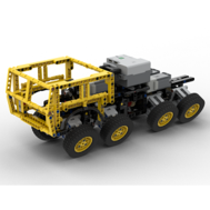 I triying to build the smallest pneumatic machine I can, 8 functions, 4 pneumatic autovalves and 5 motors but I don´t know yet... the fifth motor is just for the gearbox (yellow piece) without it I wouldn´t need a third receptor and in a small machine is a lot of extra room. Now you can see 4 motors, gearbox, 4 autovalves, the shifting mechanism and the outputs for the trasmision, I still have to put the stair and turntable mechanism, 4 pneumatic pumps, battery and 3 receptors with 1 motor or just 2 receptors, I am talking just about the body , I have to build tracks and two arms, normal and frontal type (this one needs the fourth autovalve to open and close it).
 -
Eurobricks TC10 Classic Locomotive Updates: click here for latest update on 23-Sep Objectives Model a Classic Steam locomotive that runs using LEGO pneumatic system. The Plan (best hopes) Match an elegant locomotive as much as possible Smooth run at decent speed The Initial design The idea is to create a pneumatic engine directly driving the locomotive's wheels. The engine receives power from a pneumatic compressor and can be supported by a fly wheel function to support smoother run. Other functions such as opening doors can also be implemented. Progress My target is to first accomplish the main function, getting the locomotive to run. when it starts moving I then have to try to make the run smoother. Finally, if time allows and if my parts are enough, I may try to add some extra functions. For now I built an initial structure and started the struggle to have the engine move when pumped.
-
hi all I am trying to design a small robust compressor and came up with a design that works well and uses hardly any parts pictures video
-
 So i just saw These parts: this parts came out before my "lego time" . I watched some Reviews on yt. They seem to be a bit slow. I think i could modify them a bit (harder spring etc.) Does anyone of you Afol´s have experience with these shock Absorbers used in this way?
 -
 UPDATE1: Final photos and video can be seen below, like: .... Hi! I decided to make something for TC10 competition. My plan is an underground mining loader, like the ones from CAT, etc. Functions: - pneumatic bucket tilting - pneumatic bucket raising/lowering - manual steering - 2 cylinder fake piston engine - 4x4 drivetrain The progress looks like this, will be finished until deadline IRL, I think: More progress and real life pictures coming soon. Comments, questions are appreciated, as always.
 -
 Hello everyone, For the new contest on Eurobrick, i built a scraper like this one: Functions All functions are pneumatic: - Steering by 2 pneumatic cylinder V1 2x7 - Ascent and descent of the bucket by 2 pneumatic cylinder V1 2x7 - Ejector are actionned by 2 pneumatic cylinder V2 2x11 Compressed air are produced by a pneumatic pomp small V2 and a L motor. In front, there is an 6L fake engine pulled by front wheels. Pictures Here is the first picture: Now I have to build the front of the vehicle. The rest of review later
 -
Introduction: For this contest, I wanted to model a piece of hydraulic equipment that uses a manual pumping action to manipulate the hydraulics. This would give the Technic model a natural look and feel when using the manual hand pump to activate the pneumatic cylinder(s). After much thought and searching, I landed on a hydraulic scissor lift cart. This piece of equipment will require the three main components of the Technic pneumatics system, should be compact requiring interesting mechanisms utilizing the pneumatics, and has a added bonus of being something that is rarely modeled (are there any others?) hopefully making this contest entry slightly unique! Here are some pictures I will use for my inspiration: Plan: I plan to break this model into four distinct builds: General Frame, including caster wheels and handle bar for pushing cart. Scissor lift mechanism to raise and lower the cart table using a pneumatic cylinder. Foot pump mechanism that uses the manual pneumatic hand pump to cause the pneumatic cylinder to extract. Hand brake lever mechanism that moves the pneumatic switch to cause the pneumatic cylinder to retract (based on gravity, not air pressure). Anticipated Challenges: Keeping the mechanics of all the pneumatics into a low profile so that the cart table is a low as possible when all the way down. The sliding mechanism of the scissor lift. I am not sure how to best model this and keep everything stable and strong. Translating the vertical foot pump action to a horizontal stroke that is strong and long enough to depress the pneumatic hand pump while keeping it low profile. Operating the pneumatic switch located in the cart base via a lever on the handle bar. I am currently thinking that this might be good use of the flex system! Issue here will be having enough travel to successfully move the switch far enough. Also need the mechanism to include a spring to return the lever back to initial position. Build: Part 1: General Frame Here is my initial prototype to set a standard for size and to use as a base for the different mechanisms. Part 2: Scissor Mechanism Part 3: Foot Pump Mechanism Part 3: Hand Lever Mechanism Final Model: Video:
