
gyenesvi
-
Posts
2,396 -
Joined
-
Last visited
Content Type
Profiles
Forums
Gallery
Everything posted by gyenesvi
-
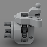 Hello Eurobrickers, Let me share my first finished model of the year, even though this one has been long overdue from last year. This time it is a fast buggy inspired by Ultra4 buggies, a variant of which I have built for last year's Buwizz camp, but I didn't get to publish it so far. The idea was to build a buggy with responsive independent suspension, but with something out of the ordinary on the rear: trailing arms with radius rods; something I have never seen implemented in Lego form. At the front the goal was to build a long travel (driven) suspension with long shocks and positive caster angle, which is not easy to do. The first implementation I built for the race was not very satisfying a bit weak and full of half stud offsets. Recently, I managed to redesign it to a more realistic and more robust form. Originally, I have designed this model with 2 Buwizz motors and one Buwizz 3 unit for the unlimited race category. However, after comparing to my fellow hungarian competitors' builds that used 4 motors, I decided to upgrade it and use 4 motors as well (at the chance of melting some axles). I managed to do an upgrade, which performed very well speed-wise, but turned out to be very hard to control (both speed and steering), so I did not fare well at the race unfortunately. I did not have much time for the upgrade, and the placement of the extra 2 motors was not ideal, was in the way for the steering motor, which I solved by adding one more CV joint to the steering actuation. This made the steering response even slower than usual and the whole car was hard to control at the race. So in the end I chose to publishing the 2-motor variant, which is more controllable, safer to use without melting and also cheaper to replicate. So without further ado, here is the usual performance video. Features Fast and powerful 4x4 drivetrain (2x Buwizz motors) Steering by PU L motor Powered by Buwizz3 unit Long travel double wishbone independent front suspension with positive caster angle Long travel independent trailing arm rear suspension with radius rods Complete interior with two seats Sleek curvy body on a tubular frame Suspension, drivetrain, chassis The whole experiment started with the rear suspension. Real high speed off-road buggies often have trailing arm suspension, which are stabilized by radius rods. I have already designed one such suspension in my Polaris RZR alternate of the Audi set. However, in that case I could only approximate the actual trailing arm and radius rod geometry with the available parts; the result was a bit of a fake variant, that's similar but not quite how it is in reality. So I wanted to build a more realistic variant of it too. On a larger scale this became possible, however, the space was still quite tight. In such a suspension, the radius rods keep the wheels moving on an arc, just like in case of a double wishbone independent suspension. At the same time, the trailing arm itself also moves the wheel on another, perpendicular arc. This is only possible if there is some wiggle room in the system, and the longer the parts (the trailing arm and more importantly the radius rods), the more flat those arcs become and less wiggle room is needed. So I had to maximize the length of the radius rods, and the 9L links were just good enough at this scale, but they had to be mounted as close to the center of the vehicle as possible, which made the space around the rear drivetrain very tight; no space for differential. No problem, it would be closed anyway on an off-road vehicle. Here is the linkage geometry I managed to implement. The planetary hubs are mounted onto the trailing arms, which was challenging to make solid, but the end result is quite good, thanks to using Defender rims, which can hide the hub assembly. The radius rods (9L links) cannot be pushed further back, that's why there's no room for differential. The 12T gears hold up surprisingly well, but knob gears could also be used, although they might not be efficient for high speeds. I didn't try. An advantage of this setup is that there's space in between the trailing arms for motors. At the front, I went for 9L suspension arms with 9L steering links, which just resulted in a feasible suspension geometry at the same width as the rear axle. However, there are a couple complications. First, I wanted to use long springs for realistic looks, which need to be mounted on the lower arm, and then somehow avoid both the upper arm and the driveshaft. This is not such an easy puzzle given the limited number of lego parts available for such a purpose. For the second try, I managed to come up with a geometry in which the shock absorber is just one stud off center, but the driveshaft passes safely next to it, and the upper arm is split in two going around the shock absorber, just like in real rigs. The other difficulty is the positive caster angle. To achieve this, I tilted the whole front of the chassis, which means that the drivetrain had to contain a CV joint. That's not an issue, but due to the single-sided nature of the 9L steering links, the steering rod could only go relatively low, close to the driveshaft, due to which it was not possible to integrate the steering motor into the tilted assembly because it would have collided with the driveshaft. So I had to add a CV joint to the steering axle too, and move the steering motor further behind. The final chassis came together like this; quite minimal but solid. The Buwizz unit is easy to access for charging or for taking it out of the model. The driveshaft itself is very simple to remain efficient. Joined Buwizz motors at the fast output, 16:16T gearing underneath and straight to the (locked) differentials (1:1 ratio), then to the planetary hubs. There would even be space for a 2-speed gearbox in the middle, but I did not want to complicate it for this one. Interior and exterior The interior has lots of space left, so I added two large seats and a dashboard / steering wheel. The shaping of the exterior was loosely inspired by the Ultra4 KOH buggy of Lazernut Racing: Besides trying to resemble the paneling using some simple flat and curved panels available in blue, I also aimed to replicate some of the tubing, both under the panels and the visible ones around the windows. The model can actually be lifter by the roof thanks to the two pillars in the middle of the windshield. Here are some renders and photos of the complete model from all angles. All in all, the model is quite fun to play with, it's fast enough but has good torque as well to climb some rocks, and the suspension is really responsive. It sits in a bit under its own weight, but is bouncy and floats nicely on uneven surface. More pictures are available on Bricksafe. Building instructions are available on Rebrickable. Let me know what you guys think of it! Cheers, Viktor
 -
Oh, indeed, looks like it. Then there's even more difference between the suspension arms and the steering links. And we cannot build a proper geometry with the 9L links either. Bummer :(
-
I also figured they are probably 8L, thanks for the reinforcement. A new length is really welcome. The new suspension arms seem 7L I guess, and with the new towball arm as extension, they form a 9L assembly together. So there's a bit of mismatch as usual.. The new arms will be usable with existing 9L links, even though they are only one sided, which is often a problem. Wish they'd also update the 9L to double sided at some point.
-
Wow, that's some amazing down-scaling! I guess the PF wire is baked in but the servo end is disconnectable? Why do you need to write the program in Assembly, what environment do you need to use? How do you even connect this thingy for programming? Through those 4 holes?
-
General Part Discussion
gyenesvi replied to Polo-Freak's topic in LEGO Technic, Mindstorms, Model Team and Scale Modeling
The Audi hub cannot be used in live axles, because of the balls built in that cannot be swapped for normal pins. If there were small (L shaped) parts with towball sockets, it would be easier to replace the old hub with the Audi one. But we are not there yet. On a similar note, it would be nice to see a revised version of the planetary hub in the form factor of the Audi hub. It would have more clearance around the steering links, and could be a swap-in replacement for the Audi hub in models. The grey one is easier to lock (also its radius is slightly smaller, needs less clearance), and the ratio is slightly different. But those are marginal differences. That one is actually quite useful still when you need that half stud extra spacer, because in many colors a half stud bush does not exist. Also, that 1 stud end feels to hold more stable than a thin version, even though half of it does not have an axle hole. I actually don't get why that is the case. It would be even more useful with a complete axle-hole end. -
General Part Discussion
gyenesvi replied to Polo-Freak's topic in LEGO Technic, Mindstorms, Model Team and Scale Modeling
Same here, I ordered on Nov 16, arrived today to Hungary. So it's not about the distance.. -
As noted above already, there are other GeekServos you could use, but the colors do matter. They exist in the same form factor as the most popular (grey) ones we all know. - the grey ones are the classic positional servos - the red and blue ones are simple DC motors (2 wires, so they need ESC), running at 180 and 90 RPM respectively - the green ones are continuous rotation speed servos, they should work off the receiver without the need for an ESC Also, GeekServos exist in the above linked weird form factor, but I think those were originally designed for studded building, so not that practical. So I'd try the green one as the simplest thing, I always wondered about it's speed / power, whether they are strong enough for a winch for example..
-
Wow, this is totally next level building, great work. Beatiful looks and seamless functioning. The cable operation lends itself to such smooth movement! How is the rear suspension made? Is it a bogie axle? It's so well hidden..
-
Thanks for all the detailed explanation! I also wondered that using the 5L liftarm with the bearing probably excludes the use of the 5x7 frame around the diff, and that would bring about other problems, but good to hear you solved that as well. I wonder if you experimented with setups using 4 BuWizz motors up-geared slightly (5:3) and then to planetary wheel hubs? I have a model with such a setup, I used it in last year's BuWizz camp, the speed was pretty much good enough, already hard to control even with Xbox controller (though the steering setup needs improvement, hence I haven't yet published it). Anyways, with that setup I did not yet have melting even after a race run of a few minutes on off-road terrain, using only plastic parts and lubrication (though I need to check the model thoroughly after disassembly, maybe I do that soon). Interesting that the PU ports provide less power, I didn't know that. Anyways, I only proposed the swap-in of the Buwizz3 unit(s) instead of the PU hub as a low-hanging fruit to improve the PU motor version now that that became the 'official' one on RB. But I understand that you don't want to focus too much on that one, maybe a pure PU variant is better to have then.
-
Thanks for all the answers! This detailed process description is quite insightful, thanks! Yes, I know about the green GeekServos, but I think having two PF motors along with 2-3 GeekServos would be quite nice for models that need steering plus gearbox maybe. By the way, I assume that the PF ports can be used to drive PF servos as well, right? I think the glued PF ports are quite simple and good enough solution for a DIY project like this. I like the simplicity of all the components used. How do you power the system? I mean can the LiPo be connected directly to the ESP, or does it need some down-regulation? The motor driver gets the full input of the LiPo, right? (apart from the control signal, which is lower I guess) One thing I wonder if this all could be made smaller a bit. Even a size that actually fits inside 9x5 (including mounting points) would be good. For example, I see that the bigger green board is the switch, from which a smaller variant also exists. Would that be sufficient? (Edit: I can see now from the list of materials that you are using the small one.) Anyway, maybe with a smaller ESP32, the whole thing could be made smaller I guess.
-
Nice to have the instructions for this model available, thanks @Didumos69! Maybe you could put a bit more images and info up there about the PU version as well though, now it seems too much focused on the Buwizz upgrade. Also, did you try driving those 3 L motors with a Buwizz3 unit instead of the PU hub? That could have better performance. And using 2 Buwizz3 units and 4 L motors for drive could actually result in a safer but faster model. Just an idea, could still fit into the space of the 2 Buwizz motors. I read back this thread but I could not find info on why you needed to introduce the liftarms with bearings/washers to the 4WD version? Did you actually damage parts without those? Was the drivetrain lubricated then? You only wrote about the RWD version destroying some parts. So would be interesting to know what are the chances if I try to build the Buwizz version without metal parts!
-
This looks like yet another really nice project @LabManager! The code looks nicely structured. I have a few questions: - What are those "other electronic components"? Is it like wires and connectors / resistors, or is it those two small green boards? - What does the BT connect to? The ESP? Or one of those smaller separate boards? - What powers/controls the PF ports, does it have a separate motor driver? Is it one of the small separate boards? Are the two PF ports separately controllable? - Are the PF connectors glued to the board? - Why can only be 1 GeekServo used when using 2 PF motors? Is it related to power (max amps) or number of output channels?
-
I wouldn't think so, otherwise all the RC products would have the same problem, no? But yeah, essentially that, would be good enough (as a start)! And proper servos for god's sake! They are used everywhere and cheap and precise.. shouldn't be too hard to integrate. I think they could actually fit into the PU system even, where the system can recognise the motor and emit the proper signal..
-
This looks really cool, nice alternative! Nice use of panels / wheel arches.
-
Oh, new electronics is a promising sign! But I as well can't imagine a system like this, even in different form factor, for RC technic sets. So I am hoping that they realized that the programmability thing for technic was not the most popular idea and they just separate Technic from the Education line and make something more plug and play for technic, such as physical controller.. Just hope we don't end up with something even worse, such as controllers tied (via firmware) to official sets..
-
Thanks for the heads up, sounds really interesting, the size of 12x24 mm is really good, would well be workable for a floating design! Looking forward to more progress when you have time for it!
-
In that case, it makes sense :)
-
Sure, but I guess you know that by submitting to Ideas you resigned the rights to sell on your own or elsewhere for several (maybe 3) years, even if it is not accepted, right? And in my opinion that very slim chance to have it accepted on Ideas is not worth the setback of several years to sell elsewhere.
-
2L Driving Rings Question
gyenesvi replied to LegoLord1880's topic in LEGO Technic, Mindstorms, Model Team and Scale Modeling
I don't think so, I guess they are designed to work with rotational selectors, such as the wave selector and the forks controlled by drums that keep them in place. -
Wow this looks really interesting with all those non-conventional angles and curves. I love how it has a sort of separate and realistically shaped chassis underneath the body, and the level of detail is also amazing! Great work! Unfortunately, I don't think cars have good chances at Ideas due to Lego being flooded with cars already.
-
Zero's workshop
gyenesvi replied to Zerobricks's topic in LEGO Technic, Mindstorms, Model Team and Scale Modeling
Oh, true, I did not think about that. -
Indeed, I hate those irrelevant edges at the bottom because those can easily get in the way depending on the exact mounting angle for example in a front engine car where there's chassis railing or suspension parts under he engine on the sides. But sometimes they can just interfere with the hood for example (say, in an inline setup). It's better if there's nothing protruding unnecessarily.
-
Zero's workshop
gyenesvi replied to Zerobricks's topic in LEGO Technic, Mindstorms, Model Team and Scale Modeling
Really cool model! I like how clean and smooth all the paneling is, and also that it has a complete and clean interior! Nice simple electronics layout, and the battery at the front under the hood is a neat idea, keeping even the bed clean! This is a great scale for building RC models. I wonder if a 2-speed gearbox could fit in there somehow without compromising the interior :) Also, I like the use of the CV joint for all wheel drive, the only thing I don't quite understand is why you used the 6L steering arm at the top? Is it just that it had a better shape for mounting? Or to act as a stopper? -
Yeah, I kind of agree with this, just making it physically challenging for the fingers does not make too much sense I guess, maybe you should try designing your own models @Fabulous Fox, have you tried that? That's an entirely different challenge compared to following instructions, and I guarantee you can spend endless time with rebuilding and perfecting stuff :) Also, you can make things so dense that it'll even be a struggle to put things together. I am just building something that where I already see that it will be a pain to route electronics and pneumatics in a tight space..
-
That is yet another, nice looking way to route it, so instead of 20:12 up-gearing, now you have 16:20 down-gearing, in total more than 2x difference, which should significantly ease the crane rotation! Hope the bracing also works out fine around it and it gets smoother!