


LegoLord1880
-
Posts
34 -
Joined
-
Last visited
1 Follower
About LegoLord1880

- Birthday 08/23/2009
Recent Profile Visitors
3,460 profile views



-
 THX!!! I went with the 4 stroke design for realism, and to preserve the engine's unique sound when running. Because of the 180 degree crank, it fires twice and then "misses" twice. Also, the original had a gear driven camshaft. I went with a chain because I ran out of space inside the block lol.
 -
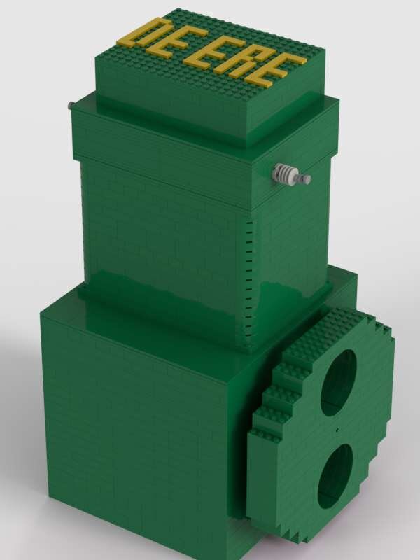
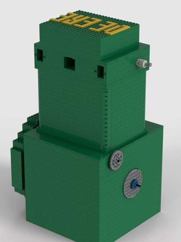
Here is a scale model engine I made, inspired by Digitaldan's 1:1 scale engine. Before I get into the LEGO version I made, let me tell a few things about the original: The John Deere Model A was a row crop tractor built from 1934 to 1952 in three generations: Unstyled, Styled, and Late Styled. It was a direct competitor to the Farmall F-20 and later the Farmall H. The engine was a transverse mounted inline 2 with a 5.5" bore x 6.5" stroke, for a total displacement of 309 ci (5.1 Liters!). Governed speed was 975 RPM. These engines were notorious for being extremely loud, and vibrated a lot with terrible power delivery. In my opinion, the only reason John Deere stayed in business was because their tractors were cheap to run. In 1934 a model A on steel wheels sold for $1,025. The comparable Farmall F-20 on steel sold for $900-$1,000 in 1934. The difference was that because of the high compression ratio, the Deere could run on may different fuels. The F-20 started on gas and switched to kerosene when warm. My model has 8x8 square pistons and a 10 stud stroke for a total displacement of 655 cc. The crankshaft is built out of 6x6 round bricks and incorporates engine1ear's caged bearing system. I built the model in Studio 2.0, and it consists of 12 separate modules: The block, crankshaft, cylinder casting, camshaft, head assembly (including valves), flywheel, 2 pistons, and 4 pushrods. All these modules add up to a grand total of: 2366 parts! https://www.tractordata.com/farm-tractors/000/0/2/25-john-deere-a.html Why only two cylinders?
-
TVS Vacuum Engine
LegoLord1880 replied to LegoLord1880's topic in LEGO Technic, Mindstorms, Model Team and Scale Modeling
Yeah, the manifold is a pretty big problem with SVS engines. You've got two options: you can either make the engine in banks of 2 cylinders and have manifolds between, or the more popular option is to put them all in one bank. The first option is only good for an I2 or U2, because you get the absolute least amount of manifold, but the engine is super long. If you want say, an I4, you have to make 2 of these units and plumb them together with a THIRD manifold! The second option isn't much better. You just make one huge manifold connecting all the valves. You either get good air volume (by making the manifold out of 4x6 plates) or good airflow(with 2x6 plates), and you have to choose which to shoot for. It's REALLY hard to get good volume or good flow anyway, because you're forced to make the interior of the manifold just 1 brick tall, otherwise it screws up the valve timing. With all this in mind, you also can't make the manifold too big, or you use up all your vacuum's capacity to suck air from it and not the cylinders. That's one major issue my TVS engine fixes. The external manifold serves only to hold the carburetor and direct intake air. All the vacuum valves are in the head, so I used the interior of the head as a manifold. -
I like OHV vacuum engines as much as the next guy, but they have more than their fare share of issues. Of course I mean the intake valve. It needs to have a hard enough spring to not get sucked open by the vacuum, but has to have the right rocker ratio and valve clearance for the engine to run well. The first work-around I've seen is to use butterfly pistons to break the seal and take in fresh air, but these also have problems. One is the piston itself. It tends to get caught on the seams between brick layers. On top of this, it only really works well with 4x4 or 6x4 pistons, and crankarms with a 2 stud radius. With these issues in mind, I went ahead and made my own fix to these problems. My new engine design is basically a classic SVS engine with a head. It uses a modified SVS valve on the side of the block to let in fresh air as the piston goes down. Then, the slide valve closes, and the poppet valve in the head opens for the power stroke. Because it uses two kinds of valves, my working name for it is Tandem Valve System, or TVS. It has all the benefits of SVS engines: It works with essentially any bore or stroke size, gets decent RPM's and torque, can be turbocharged or supercharged, and can even run on positive pressure, unlike other OHV engines. It also gets around some SVS limitations, like the manifold. The TVS engine also has the OHV benefits of realism, good sound, and the ability to make it into a four stroke. This engine ended up not even needing a flywheel, but I still used one anyway. That's not all folks! I mentioned on another thread how my vacuum engines have Water Injection, where water is pumped through the intake for extra lubrication and cooling to enhance the performance. My new TVS engine has a CARBURETOR to deliver a mist of water to the intake manifold to achieve the same effect. Here's how it works: I use a pneumatic pump submerged in water to get the water into a hose. In the carb, the pneumatic hose squirts water into the "venturi", into a minifigure spear mounted in a half-pin, which functions as the jet. The blast of water makes a fine mist, and the "richness" can be adjusted by moving the jet needle in or out. Then, intake vacuum draws the mist into the cylinders for lubrication. The carburetor also has a single butterfly valve made from a 4x3 plate which functions as the choke. When the choke is closed, it blocks some airflow and slows the engine down, while enrichening the mist. it all works quite well, and surprisingly makes a noticeable difference to running the engine without the carburetor. Now lets talk specifics: This particular engine is an Inline 2 with 6x6 pistons and a 3 stud stroke radius, for a displacement of 184.32cc, or 11.24 cubic inches. During a dyno test, it made 28 Studpower, or 0.0028 Horsepower. During the test, it made 0.03125 ft/lb of torque at 500 RPM, but peak torque when stalled came out as 0.0625 ft/lb, and a maximum speed of 2200 RPM (Not simultaneously). I think this engine design has alot of potential, and seeing as this is only the second prototype, there will definitely be a few issues to sort out. I hope you guys like it! Here is a link to where I have pictures posted on Bricksafe: https://bricksafe.com/pages/LegoLord1880/vvt-vacuum-engine/technic-starter-motor-prototype/kohler-k241-vacuum-engine-model/3-valve-vacuum-engine/tvs-vacuum-engine I also hope to have a video of the engine running and the carburetor in action soon :]
-
Or making it run off intake vacuum like the windshield wipers on old cars. THAT would be cool!
-
By water jacket, i mean places to mount the radiator against the block. they dont actually hold water lol. I'm gonna try making that engine again as an I2. oh, and you really do need a radiator submerged in water. An air tank will have WAY less surface area and will also lower the pressure in the air line
-
It looks like you already did lol. Go ahead! :) I've found it works best if you have multiple "water jackets" around the cylinder for more cooling. Sometime I'll have to borrow my dad's thermal imaging camera to see how big a difference water cooling makes
-
That's INSANE! I've never seen crankpin failure like that before! One time I had a piston weld to a cylinder wall though, and I keep both on a shelf as a kind of "trophy". Btw I've been trying to get into Discord to use TBLE but the stupid account verification is messed up somehow :p. I like your idea with lubing the crankpin. I just thought of a (complicated) way of doing that with my cooling system off the one pump actually. I'd have the air coming off the secondary radiator go into a sealed jar filled with water, and run a separate line out of the jar that would carry water. There is a really good picture of this in Sariel's "Unofficial lego technic builder's guide" book. Then I would tee off the water line and send one hose to the water injector and point the other at the crankpin to lubricate it.
-
Engine1ear has actually done that on his "life sized Lego vacuum engine" video on yt. I think its a great idea to have sleeves, but tolerances would be a major issue in getting it right, especially with how inconsistent 3d prints can be. This was actually my SECOND liquid cooling system design. The original has two radiators and works way better. With that system, plain air is pumped through one radiator submerged in a glass of ice and brine. Then the second radiator is pressed against the block. The water in the cup is what absorbs heat, the ice is to make the water colder (absorb MORE heat), and there is salt in the water to make the ice melt faster (to make the water colder, to absorb more heat. it all works together nicely). So basically, air goes through the primary radiator to be cooled, then through the secondary radiator to cool the block and fill the "water jacket" with cold air. Like I said, this cooling system works WAY better than the one in my new high performance engine( mostly because of the ice water + salt mix, and because it emits cooled air instead of drawing heat from inside the cylinder). I ran this by my dad who's worked in the HVAC industry for 25+ years, and he said it would work reasonably well as long as there is still solid ice in the glass. I'm fine with that, since these Lego engines probably don't produce much heat tbh. But it still is cool to say I invented the Water Cooled Lego engine! So why did I I use an inferior cooling system? Because I also wanted to use water injection and only have 1 pneumatic pump lol.
-
That's a good thought, and I can see where you're coming from, but lego engines really need liquid lubrication, just like real engines. Because of how leaky the seams between bricks are, we can't allow more leaks than necessary. The optimal engine does use air as a cushion to some extent though. When building a vacuum engine, you actually have to stretch the cylinder walls away from the piston a little so the engine can turn more freely. Then on the power stroke when the valve opens, the vacuum pulls the cylinder walls against the piston to make a seal, and THEN the piston is sucked up. When the valve closes, the cylinder walls relax, break the seal, and allow more free movement. We are dealing with around .0015 inches though, so the seal doesn't really "break", but there is a noticeable difference running an engine without cylinder stretching. This is partly why vacuum engines tend to not run as well on positive pressure. Also, like in gas and Diesel engines, the lubricant can be used to make the seal. The lubricant can "fill in" pitting or rougher surfaces to create seals, on top of making everything run smoother.
-
:D That's a great idea, I'll have to try it sometime! It does look like it'd draw quite a bit of power though. Since we're both lego engine innovators, I think Id better give an update on what i did and the new designs i have: The engine I did this one is a "high performance" 4x4 svs engine. Keep in mind I didn't use ANY performance designs like lightened pistons, cranks, or flywheels. Just a standard svs that I got up to 4000 rpm. You can see the mostly watertight oil pan in the picture, and the fill port where I put water in for lubrication. I use water because it makes less mess than vegetable oils, plus it doesn't leave residues, and it's thin enough to work well at high speed. The engine has splash lubrication for the bottom end, where the crankshaft dips into the water and flings it onto the lower cylinder walls. The seran wrap gasket isn't perfectly watertight though, so I have to run the engine in a 9x13 glass pan borrowed from my mom. My engine also has the water cooling system I devised, and here's where things get a little complicated. I use a pnuematic pump submerged in a glass of ice cold water to pump water through a small radiator I made. The radiator is pressed against the engine block, allowing the cold water inside to absorb minute amounts of heat from the engine. And here is the last of the 3 innovations on this engine: water injection. Water coming out of the radiator is injected into the engine's intake, which lubricates the top end. Then, the water either drips past the piston and slightly refills the oil pan, or gets sucked into the wet-dry vacuum on the power stroke. All the water action happens intermittently (bc of the manual pump), and the engine speeds up like its on nitrous when I pump water into the intake. It all works pretty well! I would love to see this stuff get put to use in other, more realistic engines (I'm talking to you, engine1ear! 🙂). I'll get some pictures uploaded and put in a link in a minute. Water Cooled Engine pics: https://drive.google.com/drive/folders/1U7hSHggFk5SBkjLve5Ibm4_0fHKgKr5v
-
Lately I've been working with poppet valve vacuum engines, which are interesting because of how much room for innovation there is. Today I built and tested a 3 valve head for one of my engines. It has one exhaust (fresh air) valve, and two intake (power) valves. I took tips for the head from the Cat D32 4 valve engine. The 3 valve head will make the engine run at around 1500 rpm, about 50% better than with its stock 2 valve head. Surprisingly, it's has about the same torque. I think this is because the engine has two intake valves to open. Any comments or suggestions for improvements will be greatly appreciated. I would also love to see someone use this to model International Harvester's gas-start Diesel engine, which was used in the Farmall MD tractor from 1941 to 1954. Pictures: https://bricksafe.com/pages/LegoLord1880/vvt-vacuum-engine/technic-starter-motor-prototype/kohler-k241-vacuum-engine-model/3-valve-vacuum-engine Inspiration: https://www.dieselworldmag.com/diesel-tractors/tractor-talk-1941-farmall-md-diesel-first-of-the-breed/
-
Hmmm. Seems like it could work, but I don't want to do anything that could permanently stick the pieces together. Maybe I'll try more plastic wrap, and between each layer. Previously I had used only a double layer on the baseplate in the bottom of the oil pan.
-
Recently I'e been doing some vacuum engine experiments. My engines always get more performance from using lubrication, but I'm wary of using olive oil, since it left a really gross residue on some of my pieces. Eventually I realized water would work just as well, but would need to be applied often because of how things it is. I came up with a splash lubrication system, which uses a sealed crankcase filled with water that is splashed up onto the cylinder walls when the piston goes down. It works great, but the water leaks out from between the bricks and constantly needs to be topped off. I've been using saran wrap between the layers of bricks, but I guess that's not enough. Does anyone have tips on how to seal the crankcase? Also, I would appreciate it if anyone has a water pump design to use for the water cooling system I developed. It needs to be able to pump water through a pneumatic hose.
-
I've been doing some experiments with my vacuum engines, and I'm trying out a splash lubrication system, using water instead of oil. An oil dipper on the end of the connecting rod and flings it against the cylinder wall as the piston goes up, and the piston is lubricated as it goes down. The only problem is, water leaks out and gets EVERYWHERE. I've been using cellophane wrap as a gasket for the baseplate it the bottom of the oil pan, and I've already accepted that I can't make shaft seals, but am I doing something wrong? Or is it just impossible to seal lego parts? Also, I would greatly appreciate it if anyone has a water pump mechanism I can use for this or my water cooling system.