
gyenesvi
-
Posts
2,396 -
Joined
-
Last visited
Content Type
Profiles
Forums
Gallery
Everything posted by gyenesvi
-
General Part Discussion
gyenesvi replied to Polo-Freak's topic in LEGO Technic, Mindstorms, Model Team and Scale Modeling
That's an interesting solution, I haven't thought about that, only problem is that in the incoming end I cannot use a stop axle to secure the small gear because that has to be a heavy duty CV joint in a live axle.. so I'm also afraid of what @keymaker is saying.. This is also a nice trick to improve it, but it mainly protects the large gears, not the small ones. If the incoming axle (without stop) slips out a bit of the 12T gear, then heavy forces can still move it and grind it up I guess.. Yeah, that's stable but the inefficiency part rules it out in heavily motorized stuff :) -
Thirdwigg's MOCs
gyenesvi replied to Thirdwigg's topic in LEGO Technic, Mindstorms, Model Team and Scale Modeling
Cool one! I thought first it's a Unimog :))) But what's a Mack Marble? I searched for it on Google and primarily found your builds :) but no real trucks in a similar form factor.. What tire size is this using? At first I thought it's Zetros size, but maybe rather 107mm? I guess the smaller DBG one is using Zetros tires? -
42177 Mercedes G500 4X4
gyenesvi replied to SNIPE's topic in LEGO Technic, Mindstorms, Model Team and Scale Modeling
My assumption is that majority of buyers have no clue what kind of pieces exist, and what pieces are new (just read some posts in FB groups). We are a small minority here who follow the part inventory. -
Sure, thanks, I'd appreciate that, standard pins sound simple enough as a start! You mean ditching PF ports? Sure that would be the best but then standard PF motors are not compatible. For not too extreme power (up to 2 buggy motors / XL motors, and up to 4 L motors) this method should work fine though.
-
I have the opposite problem, does anyone know how to receive response from Buwizz support? :)))) I had a few questions that I sent and were unanswered in the past. This one I sent lately and no response, so I ask it here as well maybe someone has experience with this. It's about control of PU motors in the Buwizz 3 protocol. I can see that there's a separate command (0x31) for advanced control of PU motors and that the interpretation of values depends on port state. I can also see that command 0x50 is used to set the port functions, and that some default values are selected for known PU motors when switching between PU servo modes. I guess those are the PID parameter values listed in the section "PID controller structure"? I also see that there's a command (0x52) to set the servo reference input (speed and position, depending on port mode). What does that reference input mean exactly? I guess for position servo, it sets the reference value to the current motor position, so that the current position becomes 0, is that right? But most importantly, I'd be interested in speed servo control. What does the reference value mean in this case? I guess the speed servo function needs a reference to know what the max possible speed is, and all other values are interpreted with respect to that? So how can I set up speed control to work properly? What value should I put there? Do I need to run the motors at max speed (inside my model under load) and set that speed to a certain value, which will mean 100% for my model, and all other values to command 0x31 will be intepreted with respect to that? Or did I get it wrong and the setup process should be something different? Another question is whether this function is available in the Buwizz App? I haven't found anything related. Precise slow speed control would be very useful functionality for the truck trial competition in the Buwizz camp in 2025. Is it possible to add it until then?
-
Speaking about PCB design, I have been looking into just that recently, and I was wondering how you made the PF connection in your RC deck. I remember seeing an image somewhere in this thread about the 'pins' going from the PCB into the PF connector, but I can't find it any more. Can you show that part? Did you use some 'standard' electronic part like a pin / pin header, or was it some custom flat bent metal part?
-
General Part Discussion
gyenesvi replied to Polo-Freak's topic in LEGO Technic, Mindstorms, Model Team and Scale Modeling
I get what you mean, but why do you think Lego started making separate spur gears and smooth running conical ones? Because they realized that they do need that performance (less friction) after all. Double bevel gears are strange for me for another reason as well. In my experience it's very rare to use both sides of it in a double-mesh, however it is really common that the unused side causes friction with a beam next to it. So they were basically opting for a rare case while not bothering with the frequent disadvantages. That feels counterintuitive. Thicker single-bevel variants with a smooth other side could have been better. But it's not always about performance. Sometimes a part wants to fulfill two distinct functions. Consider this recent one for example (or its 5x2 counterpart): It wants to be both a curved panel section and a 2x3 L shaped liftarm at the same time (on lego.com it is categorized in "beams with shapes"). As a panel, it is more-or-less okay, can join to a similarly curved 7L or 11L panel, but it has an inner corner with the cross-hole, unlike its long counterparts, which can be in the way (though can be useful for mounting in other cases). However, as an L shaped liftarm, it is often not usable, because the curve is in the way in most dense builds, exactly when a 2x3 L shape would be required (in not so dense builds, often a 2x4 or 3x3 L shape can be used instead). What is worse, is that I'd predict, that the existence of this part will block the introduction of a proper 2x3 L shape for quite some time. Sad, because it would be a very basic, very useful part. -
Interesting, to me, so far, this sounds like the most probable explanation of why all clone servos have only 3 positions; they all copied the hardware, but they could not really match the microcontroller software to it.
-
General Part Discussion
gyenesvi replied to Polo-Freak's topic in LEGO Technic, Mindstorms, Model Team and Scale Modeling
Actually I forgot about those old gears, I think they are closer to real conical gears than the single bevel gears, which are also kind of an approximation for conical ones. Also, the new gears in the Audi diff. And then the old crown gear is just that, a crown gear :) And year, I guess a double bevel gear is just a mix of conical and spur gears to allow more possibilities. However, something that's good for many things, is not really good for anything; double bevels have more friction than necessary in both configurations, and Lego is starting to realize that, and now making separate spur and conical gears (Audi). I hope this trend continues, including other types of parts (for example, currently there's not good way of making a heavy duty smooth 90 degree 1:1 gear mesh in a 3x3 space). There are so many parts that try to be multiple things, but in the end are not great for any of the options, and eventually need to be replaced by a proper part. It would be better on the long run just to have parts that are good for one clear purpose without compromising. -
General Part Discussion
gyenesvi replied to Polo-Freak's topic in LEGO Technic, Mindstorms, Model Team and Scale Modeling
Well, if you look up spur gear, it means a gear that has straight teeth, perpendicular to the direction of rotation. So it is not diagonal, and the gear is not cone shaped or beveled, just the most basic one you can imagine. Since in lego there are no diagonal teeth gears or cone shaped ones, only bevel ones, hence in lego a spur gear equals the plain ones that are not bevel gears. -
Okay, it may be that the stick is called the selector, and the orange parts are called changeover catch, rotary and fork, respectively. Though the rotary is often called wave selector.. And even in this model, the stick/selector and the shift forks are separate, and the stick moves the forks, as you can see in the assembly video above. Anyways, I guess it's clear which ones I proposed to move to the sides, there's only one gearstick and it would not make much sense to move that one.. When I say fork, I mean the fork shaped one, it's that simple.
-
General Part Discussion
gyenesvi replied to Polo-Freak's topic in LEGO Technic, Mindstorms, Model Team and Scale Modeling
I think he meant 8T. And that's just the normal 8T gear that has been around for ages. Not sure what else it could mean, if you look up the definition of a spur gear. -
Yes
-
I did not mean gears, I meant the forks. Moving gears can be an option as well, but in many cases keeping gears centered makes things simpler.
-
Looks nice and simple, though for proper RC operation, it would require supports in the middle as well, which would make it not fit into 11 long frames. Also, the standard version is quite a bit high for not too big MOCs. I wonder if a more flat design would be possible by moving the forks to the sides, one to left, one to right..
-
Thanks for the info, indeed I could look this up and starting to understand more. I meant that question about the microcontroller board of @tseary, not the ESP32-CAM board, that one seems easier as it has more connectors. No problem, no rush and thanks for the quick answers. Having looked into it, it seems that it's even possible to make such things programmable after being soldered with some suitable pinouts and microcontroller programming boards. Really curious how far this could be pushed.
-
I have been looking at the code you uploaded and kind of understand what it does. However, there are some details about the making of the hardware and the programming that I don't understand yet, so some further info would be appreciated. First, the making of the board. If I understand correctly you had the the naked board made by an online service and soldered all the components onto it manually (or are there some components that are pre-soldered?), and you have chosen each component to your needs, the main ones being the microcontroller and the buck converter, which you can just buy directly from the manufacturer and look at its docs for the pinout diagram, right? So far so good. Though I wonder if there is an online service which also pre-solders such common components onto a board if you'd like them to? Second the programming of the board. I see it uses Arduino programming. Typically, Arduino boards have a small USB connector to upload the program to the microcontroller. What I don't get is how you program the microcontroller in this one? Is there some special development board needed that you can plug the microcontroller into and use for uploading programs to the microcontroller before soldering it in? And if so, is it the case that the program cannot be changed after it has been soldered in?
-
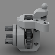
That's it thanks! It looks good on the right side of the image, and the angle also looks good enough. I'm a little worried that on the left side the edge would touch at some angle, but can image also that it just clears, have you checked that?
-
@aFrInaTi0n not exactly, I meant the same angle as the first photo just the wheel (axle) turned 90 degrees (as if the wheel was spinning) so that the other edge of the joint gets close to the pinhole.
-
Because a GeekServo is smaller, stronger, faster and more precise and have outputs on both ends :) And above all that they are cheaper as well, but that is not the most important advantage for me. PUP L motors also know their absolute position, but it's not marked on the outside, so it is a bit more difficult in that respect as well.
-
Actually that does not look as bad as I expected :) If you turn the U-joint 90 degrees can it still pass without tuching? That's the bottleneck I guess
-
Thanks, that sounds interesting! I was wondering if this board already contains a 5V downregulation of the signal which is supposed to be 9V or even higher in case of being powered from a buwizz? As for shrinkage, I think it would be possible to get rid of the pinholes (or keep at most 1) because a smaller unit does not need that much fixing, and in a housing, it could even just float in the air as well. Or a housing could have inverse studs on it just like in case of a PF plug.
-
Thanks for the explanation, so basically when using the C1/C2 to power PF motors you need the 500-800mA current, because it directly powers the motor, but when you use the signals to control the servo you don't need much current since that's only a control signal, the servo gets the power on another line, so this is why using the resistors makes sense there, right? Wow, that tiny board looks really awesome, this is almost what I was thinking. For me it would be enough to have a board that does not have an IR receiver, just the servo controller. For example, that way I could connect the servo to a Technic hub or a Buwizz unit, which does the communication for me already. I agree this would be a popular thing if published. The current form factor seems like 5x3 studs, right? How much of that space is used by the IR receiver, how smaller could that be if it only had the servo controller? Interesting to know that it could be done in theory (unfortunately I don't have enough electronics knowledge to understand those details at the moment). But if the microcontroller way results in a smaller and less problematic, than it's not worth it (and I might understand that better as a software engineer). So I'm curious about how the microcontroller path could be optimized!? If that little board could be shrunk a bit without an IR receiver for example to a 3x3 form factor, and put into some simple 3d printed housing to feel less naked, that would already be great!
-
Thanks for the answers! Indeed, that's also important :) This clarifies things, initially I thought it differently, I mixed the resistors up with something that does some signal processing of the two control signals; but now I understand that it just lowers the signals and passes both of them to the board. One thing is not clear though about the voltage divider. On one hand you have the buck converter to provide 5V signal to the ESP, and on the other hand the control signals are also transformed by the voltage divider for the same reason, because the ESP32 cannot handle 9V. So what's the difference between the two, why are two different techniques required to down-regulate the 9V signals? Is it that the power needs to be regulated precisely to 5V and for that you need a voltage regulator, but for the control signals it is enough just to lower them to some arbitrary low enough value that the board can handle? I also looked at your code and now understand that the analog control signals first get converted to duty cycle values, and then the output PWM signal for the servo is generated. I guess the Servo class which does the actual signal generation (write PWM signal with specified microseconds of frequency) is a system class on the ESP32, right? Sure, I understand that Arduino programming is much easier :) I just wanted to understand what would be required. The reason I think this should be doable electronically, is that a hobby RC receiver should have a similar circuitry if I am not mistaken. Such a receiver gets a 5V signal and GND and also receives some digitally represented control signal from the transmitter, and generates the appropriate PWM signal in its pins. Maybe in that case the task is one step simpler since the control signal is probably not analog but already digitally received from the transmitter, but the PWM signal needs to be generated. At least that is what I would guess, but I have little knowledge in electronics. So if anyone has more input on this, I'm all ears :)
-
Nice little experimental model, good start for the competition :) I like the construction of the half axles. It is weird that the two PF XL motors overheated with a 28:12 up-gearing and planetaries, that is similar to the up-gearing in 42099 with weaker motors, and many other builds employed such or even more aggressive up-gearing I think. Or maybe you were pushing it 10 minutes non-stop?