
SNIPE
-
Posts
2,678 -
Joined
-
Last visited
Content Type
Profiles
Forums
Gallery
Everything posted by SNIPE
-
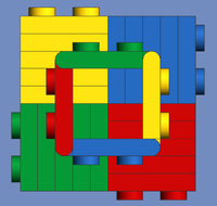
 mock up of the new hammer-drill attachment: Now both functions are independant, the drill spinning can also be done manually. I just need to modifiy the end of the excavator's boom so that the claws pivot in the opposite directions which should give space for 2 black knob wheels that mesh with the yellow knob wheels. The internal pair of knob wheels are used for the hammering, one of said knob wheels is acting as a cam, and theres a small pulley wheel acting as the follower, theres also a spring placed over the drills axle, so that the cam returns back to the pulley wheel. for now the 12 tooth knob gears are not connected to anything because I need to figure out how to fit the gears in. There also will be a CV joint that is connected to the end of the drills axle, since the CV joint has a frictionless axle hole and the axle needs to slide in and out.
 -
I have finished the model besides the bodywork and I have decided that the hammer drill will have a knob gear that mates with another knob gear at 90 degrees which is on the latching thingy, this means we can still remove the attachment but it can still be driven without having to align teeth, say on normal gears. The knob wheels obviously make the drill spin and hammer. Not sure if its possible to make those 2 functions independent. I will make it so that the knob wheel doesn't prevent the bucket from being attached. Hopefully third party attachments will use my system too :D
-
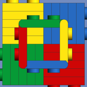
So, I did a mod + some tiny tweaks, the main is using reinforced CV joints instead of UV joints inside of the boom, I think if we move the axle for the 2nd stage linear actuator to where the lime pin is then run this thru the gearbox, we can use the existing axle line for the motorized hammer drill. Another option would be to just put a small motor in the gap shown in the first image then have extension cables going thru the rest of the boom and model to the battery box. But I want a turntable too, so I will be adding 2 more gearbox clutch rings, the functions will be: Turntable Boom stage 1 Boom stage 2 Bucket tiling PTO (used for hammer drill, and third party attachments, unused for bucket) Attachment unlatching There is also a space to add a clutch ring in the middle of the gearbox. Drive / skid steering would have their own motors and BUWUZZ in the substructure, so these dont need the superstructures motor/battery box. This is for my semi RC mod, the other version will have no gearbox and be all motors, Both versions will have LEDS
-
General Part Discussion
SNIPE replied to Polo-Freak's topic in LEGO Technic, Mindstorms, Model Team and Scale Modeling
Good catch -
General Part Discussion
SNIPE replied to Polo-Freak's topic in LEGO Technic, Mindstorms, Model Team and Scale Modeling
The black "C" cross block is very welcome :)))) -
I was going to buy this, now i'm not anymore. LEGO needs to learn. now im going to the pub
-
I'm sure it can be done but eurobricks needs to have more collaborations on MOCs and MODs. I also wanted to motorize this function for a long time, so when the set is out I hope I, or someone else makes a MOD for it!
-
WeDo 2.0 splitter
SNIPE replied to DzieX's topic in LEGO Technic, Mindstorms, Model Team and Scale Modeling
it may be possible with a 3rd party control+ Y cable or expansion hub, I've seen both before, but weather or not the hub will start shutting off power is a different story, I don't think it will but smart hubs can be a pain in the rear, like when I built my robot inventor set, only for it to want me to lock the motors off for calibration , which meant ripping the robot apart again, I tried just locking the motors off in a less invasive way but if they moved even a hair the hub would know -
unboxing Shame about the STUPID AI voiceover
-
shame you cant adjust them using a mechanism you build, only by hand I also bet you'd have to take the wheels.off to get your hand in there too
-
Maybe one day they will actually use those 2 extra motor outputs xD
-
General Part Discussion
SNIPE replied to Polo-Freak's topic in LEGO Technic, Mindstorms, Model Team and Scale Modeling
possible new wheel/tyre: (dark blue) Not sure if its rubber. source, maybe there's some other new parts/recolors that people can hunt down -
General Part Discussion
SNIPE replied to Polo-Freak's topic in LEGO Technic, Mindstorms, Model Team and Scale Modeling
I was going to suggest simply clamping it - maybe using a GBC ball between some frictionless stud pins, but I guess I was imagining a smaller scale than what you actually needed. -
General Part Discussion
SNIPE replied to Polo-Freak's topic in LEGO Technic, Mindstorms, Model Team and Scale Modeling
I wonder if we use a buwizz buggy motor + the large vinyl pieces from that technic race yaught (42174 ) but as helicopter blades, if it will fly? -
[GBC] Akiyuki Ball Factory
SNIPE replied to Berthil's topic in LEGO Technic, Mindstorms, Model Team and Scale Modeling
More GBC by akiyuki: -
I decided to start making a replica and add my mods. So far this has: two C+ L motors for drive/steering but I mistakenly mounted the tracks too low, so there will be space for two C+ XL motors once I fix that. it has two mini turntables per wheel for strength though I might change these to planetary hubs it uses 3 of the technic base-plates in black. since I need many mounting holes for the gearbox version of the MOD, I will do the RC version first however. But I did plan the gearbox, it has 8 clutch rings for the following functions: PTO (for the drill attachment) (one SP small angular motor) attachment pivoting (one M LA, one PU M motor) boom section A (two L LAs. two C+ L motors) Boom section B (one L LA, two C+ L motors) Turntable rotation Cabin elevation (one SP small angular motor) Drive (this may not need the gearbox) Steering (this may not need the gearbox) I also used the long tank treads and heavy duty differentials, and lots of girder frames. The model is modular so far.
-
I have a design for adjustable ride height (not suspension as people misname it), it supports a differential, the shocks from 42172, and steering. I'll make a digital model for them after I p1pst them on the pimp mclaren p1 tread. But how about a flappy paddle gearbox?
-
Is this Lukas2020 on rebrickable?
-
I would like a 1L diameter shock, but instead of being 6.5L, it can be built mostly from other lego pieces and has a lot of customization. I tried making a mock-up drawing by having basically an oval pinhole , like on this piece, and using a stud pin to hold the plunger inside of the body, but since I want the body to be 1x1 in diameter, the other parts would be too big. Also since the plunger is just an axle, but has a pinhole on the end, it would be too big where the pinhole is in order to be inserted into the body. which just has a friction-less axle-hole... We have the 5L axle joiner which has no friction on one end, we have just the metal springs on their own, as well as the 6.5L shock absorber body We have axles with stops in different lengths, connector pins, other connectors but what we don't have, is a way to lock the axles so that they doesn't fall out, but also lock the pinhole on the end of the plunger axle so that also doesn't fall off. So, we need a way to do that, while also allowing for a customizable shock absorber (because that's the LEGO way) IDK if anyone can come up with some designs. a mini pin and bar hole could work, in order to keep the plunger and body locked together, but its not as flexible as a pinhole, whicha ccepts studs, pins, axles, also mini pins are weaker.
-
General Part Discussion
SNIPE replied to Polo-Freak's topic in LEGO Technic, Mindstorms, Model Team and Scale Modeling
https://www.newelementary.com/2025/06/what-are-new-lego-parts-in-june-2025.html#go_to_cat_m_29 -
General Part Discussion
SNIPE replied to Polo-Freak's topic in LEGO Technic, Mindstorms, Model Team and Scale Modeling
I am praying to the lego gods that this subpart can be removed from the wheel that it comes in It has a "hard snap" but is friction-less, so it can kinda act like a 2L axle with stop -
I assume you mean a #2 connector but with pinholes rather than axle holes. If so the this acts as 2 of them :)
-
Another part I would like would be a 7 x 9 frame, because sometimes the 7x11 is a bit too long to fit in a model. yes, I could technically make one using some 9L and 7L flip flop beams but then its not 1L high anymore, and weaker, and some of the holes are needed for the pins. Here's a mock-up:
-
General Part Discussion
SNIPE replied to Polo-Freak's topic in LEGO Technic, Mindstorms, Model Team and Scale Modeling
New technic elbow/macaroni connector 45 degrees: https://www.newelementary.com/2025/05/review-10348-japanese-red-maple-bonsai.html?m=1 -
Arctic Train #60470 review is u: