Search the Community
Showing results for tags 'NXT'.
-
 OK, well the American Semi truck is a very recent MOC, but I made the European one quite awhile ago, and just never got around to uploading the pics, so.. ....here they are. European Semi truck specs: Front wheel rack and pinion steering rear 4WD only uses 2 motors, so you could build a trailer and add a/some motorized function(s) Pictures Here is the overall model Here are some pics of the front, and back. And some pics of it without the studded assemblies hiding the NXT brick. And that is it, now for the American style semi truck, and... ... the trailer with grabber Specs of American Semi truck, and trailer (with grabber) [Truck] Rear 2WD (It's on not the back axle, but the axle before it). [Truck] Opening hood. [Truck] Ultrasonic sensor for obstacle avoidance. [Trailer] Motorized grabbing arm controlled by button hidden on either side of the trailer. [Trailer] NXT Brick right, and left buttons control steering for the truck. Now the pictures, truck first. Front view of the truck View of the hood opened revealing the steering motor. Close up on the grille. Back view of the truck (revealing that the NXT brick is in the trailer, to keep the truck smaller so I would have more pieces. And now on to the trailer. Birds eye view. View from the front of the trailer And that it, I'm working on a tower crane now, if anyone wants to geve suggestions one what vehicle to build next I'm fine with I welcome that.
 -
 Background With some colleagues of mine, I am working on a fully automated train layout. You can read more about this at our blog: siouxnetontrack.wordpress.com. The layout is always demonstrated on Lego World in Utrecht. We gave a demo at another event, as can be seen on the following Youtube video. One of the items I have been working on, is the Candy Rotation Stock. I made a working version, as can be seen on the next video: Redesign of the Candy Rotation Stock After building the final version of the Candy Rotation Stock, I transported the object to our office to integrate it with the other parts of the track. I found out that the CRS was not robust enough and it took some time before it worked again. Although the concept works, it was not good enough to run for a couple of minutes without problems. And I needed it to work for four days at Lego World! So I took the difficult decision to redesign it. In this thread you can follow the progress. The redesign will be based on the conveyor belt that I found on Youtube (user ssugawara1955): And this is my proof of concept: I have ordered some extra parts to make a complete square and two switch points: one switch point that will lead to the Crane Pickup location and one switch point where new containers can be inserted to the rotation stock. Some more photos of the progress can be viewed on flickr: https://flic.kr/s/aHsk8h6MAc . Enjoy. /Hans
 -
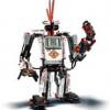
 The Robot: Model of a Lego Mindstorms NXT Sumo bot. The object of the sumo game: Push the other robot out of the ring. The objectives of our creation was to be low to the ground and still have all of the required functions. Completion date: 29/04/2012 Power: electric (NXT brick) Language: NXT-G Bricks: 1 Motors: 2 x NXT motor Sensors: Ultrasonic, Color Parts: Approx: 297 More reading. https://nxt45.wordpr...ent-sumo-winner
 -
Hello. This is my first MOC I've uploaded, but I've made many. :) So this is my RC, 6wd, LEGO Mindstorms NXT Log Skidder. For It I have one motor for driving the 6 wheels, another for steering, the last motor for lifting up the logs, and then a manually operated claw. EDIT 1, 16/5/01: I only have about 5-6 hundred LEGO Technic pieces so forgive me for any styling, look issues. :) Here are some pics (Click here for the full resolution images). A pic highlighting the re-designed log pulling arm (it can swivel around 360 now) A close the actual grabbing part of the log pulling arm. a closeup on the re-designed cabin. A picture highlighting the gullwing doors on the cabin. A picture highlighting the fact that the cabing tips up, and showing some of the (fake) machinery in the log skidder underneath the cabin. Another picture highlighting the titlting cabin, and showing some of the (fake) machinery in the log skidder underneath the cabin. A back view the the Log Skidder and the "engine" (NXT brick). A picture showing the whole model. One last picture showing the whole model.
-
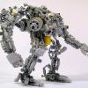 Teaser: Introduction The article describes the experience of using the Lego Mindstorms EV3 set for creating a robot prototype with software and manual control via Robot Control Meta Language (RCML). Next, we will discuss the following key points: Assembly of the robot prototype from the Lego Mindstorms EV3 set. Quick RCML installation and configuration for Windows. Robot software control based on EV3 controller. Manual control of the robot peripherals using a keyboard and a gamepad. Jumping a little ahead, I will add that for implementing control over a Lego robot via a keyboard, one will have to create a program containing only 3 lines of code. More information about it is available under the cut. Step 1 First, the Lego Mindstorms EV3 set was used for creating a prototype robot to be used for programming and manual piloting. The robot's design is similar to that of a truck chassis. Two motors installed on the frame have one common rotation axis connected to the rear wheels via a gearbox. The gearbox converts the torque by increasing the angular speed of the rear axle. The steering system is assembled on the base of a bevel gear speed reducer. Step 2 The next step is RCML preparation for working with the Lego Mindstorms EV3 set. Download the archives with executable files and library files rcml_build_1.0.6.zip and rcml_modules_build_1.0.6.zip. The following describes the quick start procedure for ensuring interaction between RCML and the Lego robot controlled by an EV3 controller. Content directory after extracting the archives Next, one has to create configuration file config.ini to be placed in the same directory. To implement control over the EV3 controller via a keyboard and a gamepad, connect modules lego_ev3, keyboard and gamepad. Listing of configuration file config.ini for RCML [robot_modules] module = lego_ev3 [control_modules] module = keyboard module = gamepad Next, the EV3 controller should be paired to the adapter. The instruction for pairing an EV3 controller to a Bluetooth adapter: The reference guide contains an example of pairing a Lego Ev3 controller to a PC running under Windows 7 operating system. Next, go to the Ev3 controller settings and select menu item "Bluetooth". You should make sure that you have set the configuration settings. “Visibility” and” Bluetooth” should be ticked. Go to "Control Panel", select "Devices and Printers", and "Bluetooth Devices". Click on the "Add device" button. A window with available Bluetooth devices will open. Select "EV3" device and click "Next". Dialog box "Connect?" will be displayed on the EV3's screen. Check as appropriate and confirm by pressing the center key. Next, the "PASSKEY" dialog will be displayed, enter digits "1234", and confirm the key phrase for pairing the devices by pressing the center key at the position with the tick image. In the pairing wizard of the device, a form for devices pairing key will appear. Enter "1234" and press "Next". A window with confirmation of successful device connection will appear. Press the "Close" key. At the PC, return to "Control Panel", select "Devices and Printers", and "Bluetooth Devices". The paired device will be displayed in the list of available devices. By double clicking, go to “EV3” connection properties. Next, go to the "Hardware" tab. By double clicking, go to the connection properties of the "Standard Serial over Bluetooth link". The COM port index specified in the properties should be used in the config.ini configuration file of the lego_ev3 module. The example shows Bluetooth connection properties of a Lego EV3 controller with the use of a standard serial port COM14. Further module configuration is limited to specifying the address of the COM port used for communication with the Lego robot in the configuration file of the lego_ev3 module. Listing of configuration file config.ini for the lego_ev3 module [connections] connection = COM14 [options] dynamic_connection = 0 Now configure the keyboard module. The module is located in the control_modules directory, then keyboard. Create configuration file config.ini next to the keyboard_module.dll file. Before creating a configuration file, specify the actions to be performed by pressing keys. The keyboard module allows using keys with a certain numeric code. The table of virtual key codes is available here. As an example, I will use the following key press events: The up/down buttons are used to rotate the rear wheels motor forward/backward. The left/right arrows turn the wheels left/right The configuration file of the keyboard module describes which axes are available for the programmer to implement interaction with the robot in the manual mode. Thus, in the example we've got two control groups - these are keyboard axes. To add a new axis, stick to the following rules of axes description. Rules for describing axes for the keyboard module. 1. In case of adding a new axis, add axis name property to section [mapped_axis] and set it equal to the value of the keyboard key in HEX format; there may be several keyboard button values for one axis. In general, an entry in the [mapped_axis] section will look as follows: axis_name = keyboard_button_value_in_HEX_format 2. You should set the maximum and the minimum values that the axis may take. To do so, add to the config.ini configuration file a section named as the name of the axis, and set the upper_value and lower_value properties for passing the values of the axis' maximum and minimum. In general, the section looks as follows: [axis_name] upper_value = the_max_axis_value lower_value = the_min_axis_value 3. Next, you should determine what value the axis will have after a previously defined button on the keyboard is pressed. The values are defined by creating a section with the name consisting of the axis name and the value of keyboard button in Hex format, separated by underscores. To set the default (not pressed) and pressed state values, unpressed_value and pressed_value are used, where the values are passed. In general, the section in this case will look as follows: [axis_name_keyboard_button_value_in_HEX_format] pressed_value = axis_value_with_pressed_button unpressed_value = axis_value_with_released_button To implement the control over the robot prototype, a configuration file of the keyboard module has been created, which includes the "go" and "rotate" axes. The "go" axis is used to indicate the direction of robot movement. When the “up arrow” button is pressed, the axis is set to 100, and when the “down arrow” button is pressed, the axis is set to -50. The rotate axis is used for setting the front wheels turn angle. When the "left arrow" button is pressed, the axis is set to -5, and when the "right arrow" button is pressed, the axis is set to 5. Listing of configuration file config.ini for the keyboard module. [mapped_axis] go = 0x26 go = 0x28 rotate = 0x25 rotate = 0x27 [go] upper_value = -100 lower_value = 100 [rotate] upper_value = -100 lower_value = 100 [go_0x26] pressed_value = 100 unpressed_value = 0 [go_0x28] pressed_value = -50 unpressed_value = 0 [rotate_0x25] pressed_value = -5 unpressed_value = 0 [rotate_0x27] pressed_value = 5 unpressed_value = 0 Next, for control implementation using a gamepad, configure the gamepad. Configuring the module includes creating configuration file config.ini next to gamepad_module.dll in the control_modules directory, followed by gamepad. Listing of configuration file config.ini for the gamepad module. [axis] Exit = 9 B1 = 1 B2 = 2 B3 = 3 B4 = 4 L1 = 7 L2 = 5 R1 = 8 R2 = 6 start = 10 T1 = 11 T2 = 12 RTUD = 13 RTLR = 16 LTUD = 15 LTLR = 14 arrowsUD = 17 arrowsLR = 18 [b1] upper_value = 1 lower_value = 0 [b2] upper_value = 1 lower_value = 0 [b3] upper_value = 1 lower_value = 0 [b4] upper_value = 1 lower_value = 0 [L1] upper_value = 1 lower_value = 0 [L2] upper_value = 1 lower_value = 0 [R1] upper_value = 1 lower_value = 0 [R2] upper_value = 1 lower_value = 0 [start] upper_value = 1 lower_value = 0 [T1] upper_value = 1 lower_value = 0 [T2] upper_value = 1 lower_value = 0 [RTUD] upper_value = 0 lower_value = 65535 [RTLR] upper_value = 0 lower_value = 65535 [LTUD] upper_value = 0 lower_value = 65535 [LTLR] upper_value = 0 lower_value = 65535 [arrowsUD] upper_value = 1 lower_value = -1 [arrowsLR] upper_value = 1 lower_value = -1 Step 3 The next step is writing a program in the RCML language. At the root of the created directory, create the program file. The name and extension of the program file may be anything, however, Cyrillic characters are to be avoided. In the example, the filename is hello.rcml. For the lego_ev3 module, the robot redundancy program code looks like: @tr = robot_lego_ev3; The lego_ev3 module connection page contains description of the majority of the features supported by the controller. As a test example, a program for automatic robot drifting has been created. The algorithm of the program is as follows: function main() { @tr = robot_lego_ev3; //Reservation robot @tr->setTrackVehicle("B","C",0,0); //Installing the engine synchronization @tr->motorMoveTo("D",100,0,0); system.sleep(500); @tr->trackVehicleForward(-100); system.sleep(1000); @tr->motorMoveTo("D",50,-50,0); system.sleep(4000); @tr->motorMoveTo("D",50,50,0); system.sleep(4000); @tr->trackVehicleOff(); system.sleep(1000); } After reserving the first available robot, two motors are paired for further operation as one. After that, the robot starts drifting. Program description of robot actions makes it possible to precisely set front wheels turn angles and rear wheels rotation speed. Using this method allows achieving the results that are difficult to replicate by manual piloting from a keyboard or a gamepad. The program is compiled in the windows command line. First, navigate to the new directory with the rcml_compiler.exe and rcml_intepreter.exe executables. Then enter the following commands. The command for compiling the hello.rcml file: rcml_compiler.exe hello.rcml hello.rcml.pc The result of compilation is a new hello.rcml.pc file in the created directory. Now make sure the EV3 controller is enabled, and paired to the Bluetooth adapter. A gamepad should be connected to the PC. After that, run the program file execution command: rcml_intepreter.exe hello.rcml A video showing the robot motion program is located below this article. Step 4 The next step is controlling the robot manually, using a keyboard. The following describes the process of software pairing of robot motors to the keyboard. Keyboard can be used for controlling any motor of the robot. Within the framework of the example, control over the following mechanisms has been implemented: Front wheels turn angle, Direction of rear wheels rotation. The algorithm of the program is as follows: function main() { @tr = robot_lego_ev3; @tr->setTrackVehicle("B","C",0,0); system.hand_control(@tr,"keyboard", "straight","go", "speedMotorD","rotate"); } Then the program should be compiled and executed. The result of manual controlling a Lego robot via a keyboard is shown in the video at the bottom of the page. Step 5 In addition to the keypad module, the gamepad module is available, which makes it possible to manipulate the robot using the gamepad. For implementing control over the robot via a gamepad, one should describe at the program level what axes of the robot will be set to the values of the gamepad axes. The algorithm of the program is as follows: function main() { @tr = robot_lego_ev3; @tr->setTrackVehicle("B","C",0,0); system.hand_control(@tr,"gamepad", "straight"," RTUD", "speedMotorD"," RTLR"); } Then recompile the program and execute it. Below is the result of manual control over a Lego robot via a gamepad, and all previously connected methods: Control Lego Ev3 by using RCML The article briefly shows only certain RCML features. A more detailed description is available in the reference guide.
 -
 Good day everybody and let's continue with the boat mania!!! Today I would like to post my experimental NXT project- The Supra Yacht. It uses two Nxt motors for propulsion , but I disn't tested the propulsion system yet. It is built on top of two 1l plastic water bottles , and all electronics are on top.Because every NXT component is on the rear of the boat I built a long mast on the front for maintain the balance. The mast is connected to one Nxt motor. Here's the video:
 -
 Just learned about this tiny Intel Compute Stick Wondering if it might be practical for use with LEGO Wedo, Minstorms NXT and EV3 BTW how are LEGO Train configured. Does it need a computer?
 -
 Should anyone be interested, the NXT Rechargeable battery is on sale for US$39.97 at the LEGO Education site. Sadly, I understand they will only ship to addresses in the US as they expect non-US customers to source parts from the LEGO designated redistributors in other countries. So in my case as I live in New Zealand, I'm out of luck but at least it is an opportunity for those members who live in the US to consider if this offer is worthwhile. Regards, David
 -
Sioux.NET on Track is a group of enthusiastic colleagues who come together after working hours to get experience with Microsoft.NET. To make learning fun, we develop an application in C# for making a full automated Lego train, using Lego Mindstorms and Lego Power functions. The layout is always shown at Lego World in the Netherlands. Our plans for 2016 have been published at our blog: siouxnetontrack.wordpress.com as well as an article about the new updated crane positioning. You can also view a video at our Youtube channel about the power chain systems: Enjoy, Hans
-
 Hello, I need advice for individual projects.I have done some work on my channel. Can you review? Waiting for your comments. Good work. https://www.youtube....m3IuBvcPALsXwGQ
 -
Several time ago I had problems with the NXT's speaker. It looks like if the speaker has corrosionrust or something like that.Is there any cheap repairs? I will post photos later. It doesn't produces the standard sounds like turning on or click and the sound files from all the programs are also in silence. (the programs work well)
-
 I am getting close to the end of this long term build and it's time to share some pictures and a bit of the story. Even before I had finished putting together 10231, I decided I wanted a Crawler to go with it. Being a Technic fan it had to at least drive around and lift the launch platform and shuttle. Those two basic goals spawned a project that has lasted a little over 2 years so far. Some ideas have stuck around since their inception, others were a bit optimistic (like building a peristaltic pump and hoping I could find a way to control the pneumatics hydraulically). February this year marked the 50th anniversary of when the two crawlers went into service, so recently there has been extra motivation to finish. The base equipment; - 16x M-motors (drive) - 4x L-motors (pneumatic jacking and leveling) - 4x IR Receivers (V1 as the V2s do not like driving multiple m-motors on a single channel) - 4x NXT servo motors (steering) - 4x RCX rotation sensors (measuring jacking level between truck and chassis) - 2x NXT bricks (one master and one slave. The master communicates with the Android Tablet and coordinates itself with the slave. Programmed in LeJOS) - 1x PF IR-Link sensor (link between master NXT and all PF motors) - 2x PF Battery boxes (with thermal overload removed) - 1x Android Tablet Future add-ons - Accelerometer (automatically detect the crawler is on a gradient and adjust the leveling to suit) Bricksafe folder is here: http://www.bricksafe.com/pages/OzShan/Crawler Firstly, a couple of my favorite reference pictures; The build itself started with the trucks, thinking that the pneumatics and LAs would dictate the scale. First proof of concept - build a coupling to give height, pitch, roll and yaw to the truck. The pneumatics need to be on their own gimbals too. The reinforced 2x2 rounds slide and rotate in the 4x4 macaroni's. It is on the limit of what will hold together without glue, but it does hold. The two 1x2 technic bricks at the base of the 2x2 column are helped a little by a string (not pictured) which runs up through the 2x2 rounds with the axle. Initial prototype of the drivetrain. I would have liked a higher ratio but there was just no room at this scale. When the gearbox was married with the truck chassis I had to juggle positions, so you will see in later pics the crown gears are facing in not out Best laid plans.... Marry studded and studless they said. It will be easy they said... Showing what will eventually be the steering between chassis and truck. The guide tube and pneumatic cylinders are all on gimbals with the pneumatics coupled together. The average height is preserved during any tilting. With prototypes sorted, it's time to bricklink some parts and quieten down the colour scheme! (thank you 42030 for providing 5L thin liftarms with axle hole in LBG color) You can see the relationship between "guide tube" and cylinders here. The pneumatic system was overhauled too many times to remember but this is what it arrived at. It is all controlled by the direction of the motor. Running forwards drives the pump. When running backwards, the lobes operate the pneumatic valves in series, letting small amounts of air escape each rotation. This lowers the chassis in a slow and controlled manner. The motor can be turned on or off and run in either direction at any time due to the valve timing. Early attempts with PF Servo and NXT servo just couldn't park the valve reliably and after a few operations I would hear a slow leak. I have been trying to keep up with the LDD but it's hard to stay motivated when I know I'm just going to have to suck it up and move over to LDraw if I want to include all the motors, pneumatics and LAs Works so far; (I'll make the files available if anybody would like them). I found LDD essential in the early days to plan ahead and simply find parts, but later on the build overtook it. Original 'box' pump. 1x PF XL motor, 4x 6L pumps running at 90 deg to each other. Very smooth but bulky. Flatter attempt in the same vein. The truck itself. The final design for the height control modules. I hope you enjoy the build so far. More pictures to come of chassis, steering, leveling and interior details. I'll leave it to others to decide what 'theme' it belongs to .
 -
 Interesting article on LEGO NXT Mindstorms. CNN News.... good publicity for LEGO!! http://www.cnn.com/2015/01/21/tech/mci-lego-worm/index.html
 -
 Back in 2013, I built and posted about my first NXT ball machine (you can view the original post at http://www.eurobrick...topic=87788&hl= if you are interested). While that machine worked, I learned a lot while building it, so I wanted to create an entirely new machine that incorporated what I learned. I also wanted to make it bigger. Now, in 2015, I have completed my second NXT ball machine. This one is almost 6 feet tall, and over 7 feet wide. The longest span is over 4 feet. It uses simpler lift mechanisms that are more reliable (though they do still jam occasionally -- I have an idea about how to fix that which I am planning to incorporate if I ever build a third one). This machine is also much less sensitive to how level the surface is that it is sitting on. As a result, this machine is a lot nicer to set up and display at a show. It is also much more open, giving people a better view of the balls as they move through the machine. Here's a YouTube video showing the machine in action: There are two possible paths through the machine. The path splits at the top of the left tower with some balls following the gray track that crosses the width of the machine several times. The other half of the balls follow the silver track that spirals down the left tower. Let me know what you think! Ben
 -
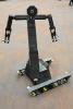 So, this has been in my garage for a couple of years and was supposed to be a mega segway, sadly LEGO MINDSTORMS motors are not powerful enough however 24 of them will move someone. First working demo of it, 24 NXT motors, 8 NXT's pure overkill
 -
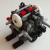 Lately I've been in the mood to make MOCs that haven't ever been done before, or improve upon unique ones. I haven't seen any descent penny sorters,so if any of you guys know of any please let me know. Copper Pennies are worth 230% of their face value just because of the metal contained in them. Some people hoard the pennies so that if they're ever taken out of circulation they could melt them down and sell the metal. I'm not one of these people, but I this would be a fun and challenging moc. There's two ways to sort copper pennies from the zinc ones without any special equipment: 1)Date: Copper pennies were made from 1909 to 1982. 2)Weight: Copper pennies weigh 3.11 grams, while zinc ones weigh just 2.5 grams. Naturally I used the weight to determine what kind of penny it is. There are two scales in the machine, each one being identical. When the penny is dispensed onto the scale if it is copper it will fall off, if it is zinc it will stay on top of the scale and will be pushed off by a fork into a different direction than the copper pennies. The entire thing is mechanical, all driven by a single NXT motor.
 -
 I'm proud to present that the LEGO GBC Pick & Place Robot module from GBC 6 has been digitized and ready for download. Also the NXT program is available on the website. Click here to download the building instructions and the NXT program. Skip to 1:33 to see the Pick and Place Robot working. Click here to support LEGO GBC 6 on LEGO Cuusoo.
 -
I'm proud to present that the LEGO GBC Pick & Place Robot module from GBC 6 has been digitized and ready for download. Also the NXT program is available on the website. Click here to download the building instructions and the NXT program. Skip to 1:33 to see the Pick and Place Robot working. Click here to support LEGO GBC 6 on LEGO Cuusoo.
-
I turned on my NXT the other day. It went pop and smoke appeared under the LCD panel. I opened her up and found the 2200 uF capacitor looked like it blew out some material. There is a hole around one of the leads. I tried testing it with a multimeter and I don't see the resistance changing over time like the other capacitors. When I turned on the NXT again, the LCD displays random moving lines. Has anyone experienced a similar problem with their NXT? Is it repairable? LEGO NXT Repair? by dr_spock_888, on Flickr LEGO NXT Repair? by dr_spock_888, on Flickr
-
I am thinking of selling one of my black NXT bricks. It is a limited edition of 1998 made. I did not buy it as a collectable, I just thought it looked interesting. I used it one or two times, but not much at all. The certificate is a PDF that the buyer can put their name on and print. I have seen prices all over the map from $180 to $280. Any interest in the Black NXT brick for $150? For $150 I will pay packing and shipping to a USA address. I also have a grey NXT brick that I will sell for $85. For $85 I will pay packing and shipping to a USA address. Or both for $200 and I will pay packing and shipping to a USA address. Any interest? Andy D
-
 Hi all! I'm programming a robot that has limited travel on one of its articulations. I don't require precision on its position, just that it stops the motor as soon as it hits the limit. NXC has the MotorOverLoad function, which appears to do exactly what I want... however, it always returns "false" even if the motor is completely stalled! Digging a bit, I found that MotorOverload is actually a shortcut for one of the fields of GetOutput (like "GetOutput(OUT_A, OverloadField)"). Checking the field's documentation, I see that, for it to work, I need to set the motor according to numerous parametres... but, after setting them, I can't get the motor to actually run! This is what I wrote to get the motor running, while enabling MotorOverload: SetOutput( OUT_C, RunStateField, OUT_RUNSTATE_RUNNING, OutputModeField, OUT_MODE_MOTORON + OUT_MODE_REGULATED, RegModeField, OUT_REGMODE_SPEED, PowerField, power_C * d); (power_C and d are variables I defined) If I use the normal "OnFwd" instead, the motor is never stopped: if(MotorOverload(OUT_C)) { Stop(OUT_C); } What could I be doing wrong? Thanks in advance!
 -
 recently the bluetooth compatibility on my mindstorms NXT 2.0 has stopped working, the mindstorms porgram now does not recognise it as a bluetooth device, it says "unavailable". I run mindstorms v2.0f5 on a 2009 macbook (wich I recieved in 2011) the computer runs on 10.8.3 mountain lion and the NXT runs on firmware 1.31. I have established that the bluetooth connection on both machines (laptop and NXT) as I can in fact pair the two devices. the problem is the NXT Retail program itself, it just does not connect making it useless, so there must be some patch to the program. I have attached a picture of the window in question, when I hit "scan" essentially nothing happens, it appears to be searching but within a millisecond the screen returns to its previous state (the state the picture shows). I watched it in activity monitor when I hit scan and the program did nothing, nothing new came up. Please respond with any ideas, questions or even possible fixes, I really need help here!
 -

The Reaper 4 x 4
Doc_Brown posted a topic in LEGO Technic, Mindstorms, Model Team and Scale Modeling
Hello everyone! I'm proud to show my latest MOC... THE REAPER This model is based on Tim Cameron's "Showtime" and other similar Rock crawlers. The chassis utilizes NXT motors geared down 3:1, and one servo for steering the front wheels only. The NXT motors are connected using adapters that allow connection to regular PF elements. This project started out as a "quick" experiment that soon got out of hand!!! I enjoyed trying out ways of joining liftarms and seeing what shapes I could get out of them. Things that I'm not too happy with are the shortness of the model, and now that I have found some better pics of Showtime I can see it should be 3-4 studs longer, and lower too. The seats were far more leaned back, but due to the rear motor needing more clearance I had to pull them forward making the cab a bit cramped. LOL As for performance, I was amazed, The Reaper will easily go up 45 degree plank of wood, that is quite smooth with no major tweaks. Turning isn't the best, but that is to be expected with no diffs; and I tried to tune it to a nice balance of turning and NON wheel tearing. This crawler has no gear grinding at all, and I am very happy with the new type 2 8t. :thumbup: also I rigged the PF lights to the steering so it kind of flashes when steered! Edit: The shocks were made from combining Unimog and old bike sets, just to keep it black. Weight is 1.320 KG. After I have made a video (prob next week, Wed) I will reuse and tweak this awesome chassis, and hopefully make something a little lower. Please feel free to comment, and ask any question's. If you would like a particular pic please ask soonish as I have the lights set up hahaha. Thanks for looking. -
 Here is my latest GBC module! It was inspired by . It was rather simple to build, but the turning mechanism took me awhile to figure out.Here is a short video I made: I am almost finished with my GBC layout, so be looking for a post about it soon! I just noticed I accidentally spelled "Mechanical" wrong in the title, sorry.
 -
 Well, I posted a lot on NXTLOG before I ever discovered EuroBricks, and so instead of reposting all of my creations, most of which weren't that great anyway, I decided to just summarize them here and provide links to each of the projects. So, here goes. I don't have any pics of my first creation on this computer, so here is just a link: http://us.mindstorms...c4-65e19addb8b4 X-1 Speed Boost Link: http://us.mindstorms...01-2421bc026580 X-1 Speed Boost Mk.2 Link: http://us.mindstorms...43-2f3d841fe7b2 X-2 Black Scepter Link: http://us.mindstorms...01-04630d644675 X-2 Black Scepter Mk.2 Link: http://us.mindstorms...01-b4874ff0b925 ULTRA (Ultimate Lego TRacked Attacker) Link: http://us.mindstorms...70-94ef06375900 X-3 Kilo-Carrier Link: http://us.mindstorms...ed-ef3ee2d5725f Z-1 Heavy Explorer (First Wheeled Vehicle) (Sorry, can't find any pics on my current computer of this one either.) Link: http://us.mindstorms...30-b4422d69267e Z-2 Rhino Link: http://us.mindstorms...65-bcee1624ef3d Z-3 Cheetah Link: http://us.mindstorms...0a-d2b191154b07 Thanks for looking!