
Hrafn
-
Posts
631 -
Joined
-
Last visited
Content Type
Profiles
Forums
Gallery
Everything posted by Hrafn
-
 When building trucks (pickups, trial trucks, etc.) that have motorized winches, do you use a dedicated motor for the winch, or use a distribution transmission from the main drive motors? A dedicated motor would be simpler, but then you'd need a separate channel for it and the motor would be dead weight when you weren't using the winch. Using the drive motors would allow re-use of the (presumably powerful) drive motors, and with a differential you could have the motors drive the vehicle forward as they also pulled the winch in - which seems useful when using the winch to self-extract the truck. On the other hand, a distribution transmission would add additional complexity. Specifically, I was thinking of (at some point) building a part-time 4x4 pickup with a winch on the front, which would have the following modes of operation: FWD high 4x4 low winch retraction (with the drive wheels in forward or neutral, for self-extraction; or the wheels locked by a brake, in order to use the winch to pull another vehicle) winch extension (by hand, using a ratchet or something similar to avoid having to back-drive the winch motor) I would probably use 2 XL motors and would lean towards using a distribution transmission for the winch. What do you think?
 -
Help me choosing
Hrafn replied to piterx's topic in LEGO Technic, Mindstorms, Model Team and Scale Modeling
I know you already decided, but as Benny might say, Stratos, STRATOS, STRATOS!!!! The bodywork will be very, very hard though. When I did my 037 I originally thought about doing the Stratos instead and concluded the bodywork was beyond my abilities - but I think you could do it! White with the Alitalia colors would be awesome, but probably a bridge too far - you'd need green and white parts, and all the diagonal lines would be very hard. -
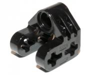
I didn't even think to check the ball's radius, thank you! Yeah, it appears to be larger than the towball that fits with the suspension arms. Oh well.
-
I was trying to figure out if this part could be used with or , or if the ball is too close to the tile for there to be much (if any) movement possible. LDraw suggests that it doesn't work well, but CAD can be misleading. Could someone who has that part try it? Thank you!
-
In principle, there are two factors to consider initially, both of which relate to getting maximum power out of your creation. First, the Lego batteries have thermal protection circuits that kick in at a given point, so there's a certain current level you don't want to exceed if you want to have your motors run for more than a few seconds. According to Philo, the 5292 motor can reach its maximum power at 1.4 Amps, if I recall correctly - but (for example) the rechargeable battery pack will shut off if you draw more than 1 A. 2 5292s powered by 3 LiPo batteries would probably give the best power to weight ratio while using about all of the available current, though you'd have to do some funny things with the wiring (PF to 9V, then use a small (PF-M or mini-motor) to control a switch that fed the 9V to the motors.) Second, any electric motor reaches maximum power at 1/2 of maximum torque and 1/2 of maximum speed. The main equations to keep in mind - which you may already know - are these. For motors: P = ω * T (ω is rotational rate, in rotations per second; T is torque, in Newton-meters; P is power, in Watts) ω = ω_max - (ω_max/T_max)*T for electric motors - in other words, there's a linear tradeoff between speed and torque P_max = ω_max/2 * T_max/2 (restating point 2, above; this might not be obvious but is derived from the first two equations) For wheels: v = ω * r (v is velocity in meters per second, r is wheel radius in meters) For batteries: P = V * I (V is voltage in Volts, I is current in Amps; fresh non-rechargeable batteries give 9V, rechargeable ones give ~7.2V, and the LiPo gives ~7.4V) As DrJB said, though, friction is important, tough to calculate in practice, and even harder to predict ahead of time. Probably the best thing to do is just observe best practices - keep your structure light and very rigid, keep axles short (and use axle joiners for longer ones, since they're more rigid), limit the number of gears you use, and use firm tires on flat, smooth, hard ground. Build a vehicle with no gearing, measure its speed, and calculate what the motor's rotational speed must be. If it's not close to half the theoretical maximum rotational speed for the motor, adjust the gearing and try again.
-
[MINI] Stratosphere Fair Ride
Hrafn replied to W3ird_N3rd's topic in LEGO Technic, Mindstorms, Model Team and Scale Modeling
That's a nice little MOC! It's nice to see things other than cars and construction machinery (though I love those too). No matter how many parts I have, I always find myself thinking I don't have enough - but this model points out how having to operate on a lean "parts budget" can really be a spur to creativity. -
[MOC] Galloping Horse
Hrafn replied to touthomme's topic in LEGO Technic, Mindstorms, Model Team and Scale Modeling
This is really amazing! What is the part that you used for the hooves? Would there be any way (a linkage or a couple of rubber bands, maybe) of making the hooves move a bit, or do they have to be fixed relative to the end of the legs? -
[MINI] D3K's WIP topic
Hrafn replied to D3K's topic in LEGO Technic, Mindstorms, Model Team and Scale Modeling
Beautiful! This is better than most official sets, especially considering how few parts it uses. I like the new tailgate, too. -
This is a great idea and I like the execution! A bit more color would make it pop more visually, though. What about the bright red cab design of the steam shovel in the classic children's book "Mike Mulligan and his Steam Shovel"?
-
Transfer Case: 2 Hi to 4 low.
Hrafn replied to sdotcarter's topic in LEGO Technic, Mindstorms, Model Team and Scale Modeling
Yeah, I realized that right after posting it. There are ways of dealing with that issue (ratchet clutch, second driving ring disengaging the front prop shaft, etc.) but then the design is no longer more compact than the original. -
Transfer Case: 2 Hi to 4 low.
Hrafn replied to sdotcarter's topic in LEGO Technic, Mindstorms, Model Team and Scale Modeling
I just realized one way to make aeh5040's design more compact while also adding the ability to lock the differential while in 4x4 mode. The differential case should be driven. When the driving ring is to the left, it's 2WD high mode; in the center, 4WD low with an open diff; and to the right, 4WD with a locked diff. -
Uses for "useless" Technic parts?
Hrafn replied to Hrafn's topic in LEGO Technic, Mindstorms, Model Team and Scale Modeling
I saw them used once as landing gear for a Millennium Falcon-like spaceship. But yeah, a Technic use (other than the intended one of storing rubber bands, which they work decently for) is hard to imagine. -
Uses for "useless" Technic parts?
Hrafn replied to Hrafn's topic in LEGO Technic, Mindstorms, Model Team and Scale Modeling
It's a pity they're so large. The one on the right would be great for using with a 40t gear, but the partial 24t gear attached to it is awkward. Aha! That's very good to know, thank you. That could be a useful combination. Also good to know! I'd noticed the groove on the back of that part before but never realized it would interface with a rail. Indeed! This part seems pretty hopeless though. -
I'm curious if anyone has found good uses for any of these parts. They're listed as being Technic parts in BrickLink, but most of them seem to me to be marginally useful at best. Are there other Technic parts that you find useless?
-
Pin, axel, - color - retoric question
Hrafn replied to AOW's topic in LEGO Technic, Mindstorms, Model Team and Scale Modeling
Also, while the blue 3L pin has friction, the tan 3L pin does not. -
One question - have you considered using instead of , and using a 20t single-bevel gear to drive the axle? That way you could get the center of the U-joint lined up with prop shaft axle, and both half-shafts would be of equal length. EDIT: it wouldn't quite line up, but it would get you 1/2 a stud closer to lining up.
-
People have used vinyl dye (here and here). Some people have apparently also used RIT dye, though others swear it doesn't work. That said, vinyl is highly toxic (carcinogenic, among other things) and RIT isn't exactly good for you either.
-
This is brilliant, thank you for sharing it! I'm totally going to use this for an AWD rally car of my own.
-
For some reason, I really want to see this mounted to the front of a low-slung supercar.
-
Extreme Bridge Layer
Hrafn replied to Zerobricks's topic in LEGO Technic, Mindstorms, Model Team and Scale Modeling
Very clever! I wouldn't have thought of doing a scissor bridge, and I'm very impressed with its strength. -
It's possible that part of Lego's deal with TRU and Walmart is that S@H won't offer sets that aren't being made available to the brick-and-mortar stores. Maybe the 2013 sets were designed by GM and they're fixing some bugs...
-
That looks very useful, thank you! Is there any chance you could post a copy somewhere other than MediaFire? It has a bunch of dodgy-looking pop-unders and seems to be somewhat unsafe.
-
Gears, most wanted
Hrafn replied to efferman's topic in LEGO Technic, Mindstorms, Model Team and Scale Modeling
Great job! I really want one (well, three) of these now. -
Gears, most wanted
Hrafn replied to efferman's topic in LEGO Technic, Mindstorms, Model Team and Scale Modeling
Ah, OK, that makes sense. f you can keep it compact by eliminating the spur gears, that would be awesome. -
Gears, most wanted
Hrafn replied to efferman's topic in LEGO Technic, Mindstorms, Model Team and Scale Modeling
That looks great! Is there any reason you've only chamfered the corners on one side? How long are the helical gears - 2L? How would you drive the differential frame? Every illustration of a Torsen diff I've ever seen also includes spur gears - the paired helical gears mounted to the diff frame don't mesh directly. Your version seems to make more sense, but surely there's a reason that the real-life ones add spur gears.