
Hrafn
-
Posts
631 -
Joined
-
Last visited
Content Type
Profiles
Forums
Gallery
Everything posted by Hrafn
-

[Help] Teaser and Hood Problems
Hrafn replied to unimog123's topic in LEGO Technic, Mindstorms, Model Team and Scale Modeling
Very nice! I may steal that suspension setup myself. -
[Help] Teaser and Hood Problems
Hrafn replied to unimog123's topic in LEGO Technic, Mindstorms, Model Team and Scale Modeling
That's a really interesting solution! I guess it's too wide to use a transverse 6.5L spring to connect the two sides. One other option (if you have the longitudinal room) is to use a bell crank on each side, and run the shocks longitudinally, something like the Rover P6: -
[Help] Teaser and Hood Problems
Hrafn replied to unimog123's topic in LEGO Technic, Mindstorms, Model Team and Scale Modeling
Looking forward to seeing it! Can you just swap in some different shocks with harder springs? Alternately, can you move the mounting points for the springs? The more vertical the springs, and the closer to the wheel they attach to the suspension arms, the stiffer the suspension should be. -
Gears, most wanted
Hrafn replied to efferman's topic in LEGO Technic, Mindstorms, Model Team and Scale Modeling
20t = 10mm radius; there is 3*8mm = 24mm between the two; so the new gear should have (24-10)=14mm radius and 28 teeth. Similarly with the 16t (8mm radius): (24-8) = 16mm radius and 32 teeth. A simpler calculation is: Distance in mm between axles = average number of teeth of the two meshing gears. -
Gears, most wanted
Hrafn replied to efferman's topic in LEGO Technic, Mindstorms, Model Team and Scale Modeling
28t double bevel is the only gear I'd want. Right now you can use the small turntable to simulate a 28t gear, but it's an awkward and bulky solution. -
I count 30 tread links on the first image posted, which would equate to 60 teeth on the gear.
-
PF Wiring Question
Hrafn replied to Blakbird's topic in LEGO Technic, Mindstorms, Model Team and Scale Modeling
Interesting! Do you have any more details as to how to do that? Never mind, I found it. 9V box -> converter cable -> empty PF battery box -> cable -> receiver -
[MOC] 1:10 Lancia 037 Rally Car
Hrafn replied to Hrafn's topic in LEGO Technic, Mindstorms, Model Team and Scale Modeling
I made a very, very basic video so you can get an idea of the car's speed and turning radius. I'm not sure how to embed a video from Flickr, so hopefully this link will work. -
Leviathan Airboat
Hrafn replied to Sariel's topic in LEGO Technic, Mindstorms, Model Team and Scale Modeling
For large, low-draft boats there are a couple of other options, but they're not one piece so they're more likely to leak and sink. There are some modular 22-wide ship units, and for extremely low draft you might be able to use the (24 studs wide?) hovercraft base (probably inverted, with the gaps covered by 8x16 tiles). The latter would probably leak and might not have enough draft, though. -
PF Wiring Question
Hrafn replied to Blakbird's topic in LEGO Technic, Mindstorms, Model Team and Scale Modeling
Philo's PF page should have the answers you're looking for; in particular he has this diagram, with dotted lines indicating channels that are not used: His diagram suggests that the receiver only needs 0V and 9V in, and C1 and C2 out. Motors need C1/C2 in, and I would guess lights are the same. The servo needs all 4: 0/9V for power, C1/C2 for angle. -
[WIP] Mercedes G Wagon
Hrafn replied to Pat-Ard's topic in LEGO Technic, Mindstorms, Model Team and Scale Modeling
You've really nailed the shape - it looks great! -
[MOC] 1:10 Lancia 037 Rally Car
Hrafn replied to Hrafn's topic in LEGO Technic, Mindstorms, Model Team and Scale Modeling
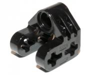
Thanks! I would never have developed that suspension without the help of many Eurobricks members (including seeing Piterx' inspired use of the black 3L-with-ball part). The roof turned out OK considering my limited time and the fact that I ran out of basically every size white liftarm except for 3L. I was trying to suggest the strange "double bubble" roofline the real car has: I'd love to see if someone can make a more robust version of my suspension. Right now the wheels eventually work themselves a little bit loose, and the top and bottom halves of the kingpin wobble somewhat relative to one another. -
[MOC] 1:10 Lancia 037 Rally Car
Hrafn replied to Hrafn's topic in LEGO Technic, Mindstorms, Model Team and Scale Modeling
Thank you all for the kind words! I'm looking forward to seeing your Stratos! I considered doing that instead, but the body shape is so complicated - the 037's bodywork was a lot easier to do. I have a second RC motor, but even with one motor the LiPo bttery is always just on the edge of having its current overload protection kick in, so I'd need a second battery in order to add a second motor. Thanks! For most things I like the new panels, but those two old small ones really fit the bill for the section under the headlights. I do hope to put up a video, but can't promise anything. I managed to drop my camera lens-down at the end of shooting these photos, and I'm not sure how long it will keep working -
[MOC] A.L.T. 6x6 mkI
Hrafn replied to Doc_Brown's topic in LEGO Technic, Mindstorms, Model Team and Scale Modeling
No, it doesn't. Buoyancy is a function of density: the mass of the tank, plus the mass of the air in it, divided by the tank's volume, should be a lower density than water for it to float. The only way to make the tank more buoyant would be to suck air out of it and create a partial (or complete) vacuum inside, but the effect would be small and the tank would likely get destroyed by atmospheric pressure if you had a vacuum inside. -
This is my first ever completed Technic MOC, originally inspired by Piterx' Lancia Fulvia but much simpler. It's not quite done, but I anticipate being able to spend very little time on Lego in the next year or two, so it's as finished as it's probably going to get. There is no gearbox or interior, and there are a number of things I'd change if I had the time - but overall I'm pretty pleased with it. The 037 was the last rear wheel drive rally car to win the WRC, in 1983. It raced in the infamous Group B category, which had few restrictions on vehicle design and engine power; as a result, the overpowered cars were in a number of fatal accidents, and ultimately Group B was abolished. While it lasted, though, Group B saw some spectacular driving and some extremely fast and loud cars. The Martini Racing stripes are done with washi tape (fancy Japanese colored masking tape), which works OK except where the tape crosses pin holes. It actually looks better in person than in photos. As in the original vehicle, the hood and rear lift up, and the doors open and more or less lock in place: Also like the original, the model is mid-engined. I used 1 RC motor geared 12:20 from the fast output. Until I put the bodywork on, the car could do handbrake turns and drift on wood floors, but now that the vehicle weighs 1030g, it can't drift and can only rarely do handbrake turns. I'm especially happy with the front axle, which includes a decent wheel lock, caster, unequal length wishbones, near-Ackerman steering, and a scrub radius of nearly zero. My thanks to all of those here who offered advice on suspension - I learned an enormous amount from you all. Steering is by servo, which offers return to center, reasonable speed, and high torque. I use a basic remote because the train remote is too slow for me to keep the car from crashing; the downside to that is that proportional steering is impossible. Wheel lock, steering, and scrub radius: Caster: The hub is held together by the 4L axle with stop (and the half bush on it), which turns out to be a more robust solution than I'd expected: The rear suspension is a modification of Thirdwigg's floating differential. It works well, with one caveat. Every once in a while, the 3L axle driving the 20t gear slips towards the differential a bit, and once when this happened a 3L u-joint got destroyed by torsion. The rear suspension is hard and has limited travel, and the suspension arms are tilted up even at rest; I would fix that if I had time. And of course the obligatory under-chassis shot:
-
How the RC system works - a video
Hrafn replied to Sariel's topic in LEGO Technic, Mindstorms, Model Team and Scale Modeling
Yeah, that's exactly why I haven't tried it. Having an auxiliary output would make the unit much more useful to me but I'm not willing to risk what I have now. -
How the RC system works - a video
Hrafn replied to Sariel's topic in LEGO Technic, Mindstorms, Model Team and Scale Modeling
Is it possible to add an auxiliary output to one of the RC units that didn't come with one? -
Small mining dump truck
Hrafn replied to jorgeopesi's topic in LEGO Technic, Mindstorms, Model Team and Scale Modeling
Awesome! Small is definitely beautiful. -
My LTM 1350 6.1
Hrafn replied to Zwergi's topic in LEGO Technic, Mindstorms, Model Team and Scale Modeling
Zwergi, That's a great looking crane! I look forward to seeing your further progress. If you want any help with posting in English, ask around - I speak a little German, and I'm sure there are other EB members who would be happy to help out. [Wenn Sie etwas Hilfe moechtest, im English zu schreiben, koennen wir hilfen. Ich spreche ein bisschen Deutch, und glaube es gibt hier andere Menschen, die koennen auch hilfen.] For non-German speakers, his initial post said (roughly) that over the last couple of months he's been building this as an auxiliary crane for his LTM 11200 crane. It can currently drive and he is now working on the crane portion, including the V-shaped portion (the two struts that stick out behind the main boom, over the ends of which cables run - I don't know what they're called). -
Thanks for the link! I'll have to peruse that carefully and try a few experiments.
-
[WIP] Unimog 416
Hrafn replied to That_LEGO_Guy's topic in LEGO Technic, Mindstorms, Model Team and Scale Modeling
Looks like maybe? How well do they work as shocks? -
Could you expand on that? How did you use the plates to connect them, since the 9V system only has 2 wires and the PF has 4?
-
I just tested this and ran into a snag relating to the extension/converter cables. Each cable has two ends; the light bluish gray (LBG) end has a PF connector on top and a 9V on the bottom, while the dark bluish gray (DBG) end has PF on top and bottom. Only the DBG end will attach to the top of the battery boxes. This means that each battery box has a wire connected to it, with the LBG end of the wire free. There is no way I can see to connect the two LBG ends exclusively through their PF sides. This is critical, because it appears that the receiver can only be powered through the PF side. Can anyone else verify that this is a real problem? Am I just missing something? There is an alternative, if you have a switch (PF or 9V; 9V is easier) and a spare PF-M motor. Use extension cables on the two battery boxes to connect them to one side of the switch, and more cables on the other side to connect the motors. Then operate the switch with a PF-M motor connected normally to a receiver. I just tested this and it works. For a real vehicle you'd also need to add in something (a hockey spring or rubber bands) to make the switch return to center when the PF-M motor turns off, and stops to keep the motor from moving the switch too far in either direction. Schematically: battery box -> DBG end of PF cable -> LBG end of PF cable -> [9V cable] -> 9V switch -> 9V cable -> RC motor The 9V cable in brackets is only needed for the 2nd (and 3rd, etc.) battery box. 9V electrical plates would also work in place of any of the 9V cables.
-
Torpedo Trike, going at 20.78 km/h
Hrafn replied to Sariel's topic in LEGO Technic, Mindstorms, Model Team and Scale Modeling
Maybe a meeting hall of some sort? Or an indoor arena? -
offset axles
Hrafn replied to Dans lego's topic in LEGO Technic, Mindstorms, Model Team and Scale Modeling
The one downside I can think of to doing what you've pictured is that when U-joints are angled, the rotation they transmit is not at a constant speed. This means your vehicle may seem to move in a series of pulses instead of at a constant speed.