Recommended Posts

That looks good! does the front axle collide with the servo when the suspension is depressed? 

I would also try to support the differential outputs on the rear axle a bit more. 

Myers 

Edited by Myers Lego Technic

Share this post


Link to post
Share on other sites
2 hours ago, Myers Lego Technic said:

That looks good! does the front axle collide with the servo when the suspension is depressed? 

I would also try to support the differential outputs on the rear axle a bit more. 

Myers 

No and I will do that.

Share this post


Link to post
Share on other sites

Can you post a picture? I'm guessing that the drag link has too much of a vertical angle, you want it too be at horizontal as possible to minimize bump steer.

Pitman-Knuckle-Draglink.jpg

Share this post


Link to post
Share on other sites
On 2017-03-16 at 9:23 AM, Lego2016Lego said:

Is this better? It has two differentials, is 4X4. and is more realistic.

33223174036_4cb777e6f0_c.jpg

Sorry to be the bearer of bad news, but the rear suspension is far from functional.  I will list the issues, the solution is to redesign it:

  • The ball joint can move up and down, which is what you want.  It can also move sideways, so you need stabilizer links, just like in the front.
  • Shock #1: the stabilizer links will limit the sideways travel, but it will still exist.  Your shock absorbers can rotate sideways, they also need to rotate parallel to the car frame.  Many builds use this piece on each end of the shock absorber:
    41678.png
  • Shocks #2: the sideways movement will put stress on one of the shock absorbers.  Leave at least 1 stud between the ball joint section and the shock absorber.
  • Shocks #3: as you compress the spring, the black bracket to which the bottom of the shock absorber is attached will want to separate from the frame.  It should sit on top of the frame, or be attached on the side.
  • The wheel supports should be beefed up.  They are held by a single axle and will flex (and eventually come apart) quite a bit.

I suggest downloading the instructions for the 9398 chassis - they show how to build strong pendular suspensions.  Yours will be much simpler, but the same principles will still apply.

Good luck.

EDIT: 42005 will probably show you just as much, and it's much simpler.

Edited by BusterHaus

Share this post


Link to post
Share on other sites
21 hours ago, JJ2 said:

Can you post a picture? I'm guessing that the drag link has too much of a vertical angle, you want it too be at horizontal as possible to minimize bump steer.

Pitman-Knuckle-Draglink.jpg

here is pic

33696887536_f0a5029907_c.jpg

20 hours ago, BusterHaus said:

Sorry to be the bearer of bad news, but the rear suspension is far from functional.  I will list the issues, the solution is to redesign it:

  • The ball joint can move up and down, which is what you want.  It can also move sideways, so you need stabilizer links, just like in the front.
  • Shock #1: the stabilizer links will limit the sideways travel, but it will still exist.  Your shock absorbers can rotate sideways, they also need to rotate parallel to the car frame.  Many builds use this piece on each end of the shock absorber:
    41678.png
  • Shocks #2: the sideways movement will put stress on one of the shock absorbers.  Leave at least 1 stud between the ball joint section and the shock absorber.
  • Shocks #3: as you compress the spring, the black bracket to which the bottom of the shock absorber is attached will want to separate from the frame.  It should sit on top of the frame, or be attached on the side.
  • The wheel supports should be beefed up.  They are held by a single axle and will flex (and eventually come apart) quite a bit.

I suggest downloading the instructions for the 9398 chassis - they show how to build strong pendular suspensions.  Yours will be much simpler, but the same principles will still apply.

Good luck.

EDIT: 42005 will probably show you just as much, and it's much simpler.

Thank you and will do.

Share this post


Link to post
Share on other sites
2 hours ago, Lego2016Lego said:

here is pic

33696887536_f0a5029907_c.jpg

Your Pitman arm is not long enough, make it a 3L or 2.5L using cams.

Share this post


Link to post
Share on other sites
10 hours ago, TechnicRCRacer said:

Amazing! It is so small, yet realistic! I hope that there will possibly be instructions!

I don't do that, but when I take it apart I will take some pics so you can reverse engineer it. If you wanted to know, it is going to be a Jeep JKA Independence.

Share this post


Link to post
Share on other sites
14 hours ago, TechnicRCRacer said:

Amazing! It is so small, yet realistic! I hope that there will possibly be instructions!

And thanks.

Share this post


Link to post
Share on other sites

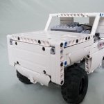
I am going to stop working on the jeep jk8 right now and make a new MOC. Probably a big slammed truck like this:


Edited by Lego2016Lego

Share this post


Link to post
Share on other sites

Here is the chassis for the slammed truck I am making. It has a dif, 2 wheel drive, 2 L motors, a servo motor and is going to have lights.

33187530114_189d8b99b8_c.jpg

33187528764_b6f2e1b6a0_c.jpg

33218152713_e8083d01d5_c.jpg

Please comment.

Share this post


Link to post
Share on other sites

Here is a C model for the Lego dump truck. It is a monster Hummer. I just have the one dump truck for Legos parts, as I sold the rest.

35535698540_1f1ca0a9fb_z.jpg

35084364934_e4d14c29d5_z.jpg

35792328591_8e2cc2f4e5_z.jpg

35535704120_b1653a216f_z.jpg

35535707600_3719b29fc1_z.jpg

35924193495_53eaf7b9db_z.jpg


Edited by Lego2016Lego

Share this post


Link to post
Share on other sites

Hi guys, long time no see! As some of you may know I sold my Lego's over a year ago. I have just got back into it and have been working on a mini crawler.  My part supply is limited so apology's in advance if something seems like it is built weird, it may be because I don't have the parts I need to build it properly. Ok, now that we got all of that out of the way I need some help on this build. if you guys can point me in the right direction to make a small front axle for this that would be great. I don't have any PF but I am trying to make it so if I get some it will be easy in incorporate.

My max size for uploading is 0.1MB so I can not upload photos.

Share this post


Link to post
Share on other sites

Create an account or sign in to comment

You need to be a member in order to leave a comment

Create an account

Sign up for a new account in our community. It's easy!

Register a new account

Sign in

Already have an account? Sign in here.

Sign In Now

  • Recently Browsing   0 members

    No registered users viewing this page.