
Equilibrium
-
Posts
169 -
Joined
-
Last visited
Content Type
Profiles
Forums
Gallery
Everything posted by Equilibrium
-
Custom LDD bricks and fixes
Equilibrium replied to Equilibrium's topic in Digital LEGO: Tools, Techniques, and Projects
In 3D Max you'd average vertex normals on surface edges for both meshes so their vectors points in the same direction. -
Custom LDD bricks and fixes
Equilibrium replied to Equilibrium's topic in Digital LEGO: Tools, Techniques, and Projects
@suenkachun Yea, just a typo -
Custom LDD bricks and fixes
Equilibrium replied to Equilibrium's topic in Digital LEGO: Tools, Techniques, and Projects
@suenkachun Try making textures of these dimensions: 3024; 1024x412 then resize it to 1024x512 3032; 1024x204 then resize it to 1024x256 3623; texture from 3032 will be streched, try 1024x136 then resize it to 1024x256 34103; 1024x114 then resize it to 1024x256 -
Custom LDD bricks and fixes
Equilibrium replied to Equilibrium's topic in Digital LEGO: Tools, Techniques, and Projects
@suenkachun I mentioned black just so you can see white lines :P I also just checked how this particular texture looks like in 3D Max, it seems that LDD doesn't tile it (repeat). So this part can be ignored. -
Custom LDD bricks and fixes
Equilibrium replied to Equilibrium's topic in Digital LEGO: Tools, Techniques, and Projects
@suenkachun Checkered background is your texture, green lines are brick's texture surface borders: if green border was same size as background you'd get 1:1, if a border is smaller then background stuff beyond borders won't get displayed but grid spacing is important! In this example models polygons are in similar size but grid gets shrinked closer to its sides. This mean image will be distorted (in this example stretched) between green line and first white vertical line next to it the most, if a border extends beyond background then texture will get repeated. Bitmap texture view How it looks on a surface This is what I mean in 1c point. 1024x1024 uv map with alpha, save as png and add some black background layer below it: @Mobieus69 Yes, but changing it would break every existing decoration. -
Custom LDD bricks and fixes
Equilibrium replied to Equilibrium's topic in Digital LEGO: Tools, Techniques, and Projects
@suenkachun That's nice, I'm glad it helped -
Custom LDD bricks and fixes
Equilibrium replied to Equilibrium's topic in Digital LEGO: Tools, Techniques, and Projects
@Stephan Yea, try to stick a bar into narrower side of 6111 brick. It will go through. Anyway I replaced negative signs inside 55 files. Collisions itself will now work but there still might be issues if they were made too big or something. @suenkachun Try now, I'm curious if it was the case. Download Link -
Custom LDD bricks and fixes
Equilibrium replied to Equilibrium's topic in Digital LEGO: Tools, Techniques, and Projects
@suenkachun I'm not sure if it is the cause of your particular issue but its an error that keeps popping up. I've searched through files and it seems there are at least 20 bricks affected. I'll look into fixing all of them tomorrow. -
Custom LDD bricks and fixes
Equilibrium replied to Equilibrium's topic in Digital LEGO: Tools, Techniques, and Projects
@suenkachun Heh, plus its side collisions are turned inside out (negative scaling) so they are not working. -
Custom LDD bricks and fixes
Equilibrium replied to Equilibrium's topic in Digital LEGO: Tools, Techniques, and Projects
Tested this a bit more and turns out manually resetting normals was enough, these vertices don't even have to be removed (at least in 3D Max). So main issue is related to normals reset in blender (from what I read it is advised to remove loose vertices there for example). -
Custom LDD bricks and fixes
Equilibrium replied to Equilibrium's topic in Digital LEGO: Tools, Techniques, and Projects
I don't know about blender but 3D Max has a button for that xD (bottom right corner) Removing them and resetting normals manualy fixes the problem. You could try to select all polygons and move them away, then (if blender has it) switch to showing vertices and it could look like this: -
Custom LDD bricks and fixes
Equilibrium replied to Equilibrium's topic in Digital LEGO: Tools, Techniques, and Projects
Ok, I know what's up. You have free-lying vertices that aren't part of any polygon/surface. -
Custom LDD bricks and fixes
Equilibrium replied to Equilibrium's topic in Digital LEGO: Tools, Techniques, and Projects
Updated :) -
Custom LDD bricks and fixes
Equilibrium replied to Equilibrium's topic in Digital LEGO: Tools, Techniques, and Projects
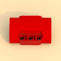
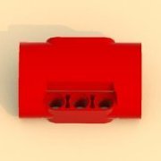
These 2 bricks look completely normal for me. @Stephan Regarding that brick. Can you upload .g file so I can check it? -
Custom LDD bricks and fixes
Equilibrium replied to Equilibrium's topic in Digital LEGO: Tools, Techniques, and Projects
There's definitely something wrong with that spot, either bad normal or something welded there. -
Custom LDD bricks and fixes
Equilibrium replied to Equilibrium's topic in Digital LEGO: Tools, Techniques, and Projects
Sounds like you welded top with sides. Can you post a picture? -
[WIP] Red Coupe RC
Equilibrium replied to Daniel-99's topic in LEGO Technic, Mindstorms, Model Team and Scale Modeling
Green didn't look bad either -
Custom LDD bricks and fixes
Equilibrium replied to Equilibrium's topic in Digital LEGO: Tools, Techniques, and Projects
To @Stephan and anyone willing to make better outlines: So there are two main factors (+ minor one) that determine how Brick Studio generates outlines: Angle between neighbouring edges (I don't remember exact number and my understanding is probably simplification of how it actually works). Groups of polygons that are welded together (that is when you grab a single polygon/triangle it resizes/moves neighbouring ones not only itself alone). Outlines will be generated for their borders. In 3D Max there's an option to select by "Element" which selects the ones welded together. Don't know about Blender. Also some space is needed between edges to display an outline. If outline in question doesn't generate nicely only due to 1st point then it can be fixed with rather simple Brick Studio trick: Let's take 73682 brick, it appears that model mesh is ok but outline wasn't generated as we would expect: So, we open Brick Studio, select brick mesh and click on "Separate meshes". This will allow us to move groups of polygons that are welded together: Then we move one of the surfaces somewhere up/down/to the side and click on "Calculate outlines" after that we move that element back in place by setting its position to 0: We export the brick and we're done :) Now, regarding 2nd and 3rd point: Let's see how I improved outlines of 73507: First left circle. There was not enough space between edges to generate outline so it was possible to fix by simply removing one of the edges (on the left) and connecting vertices differently (on the right): Now right circle. There were 3 different, not welded/connected together surfaces at which border Brick Studio was trying to generate outline: By cutting one of the polygons (to get 3 vertices) and welding them together we achieve one surface: And one more brick 73109: Two not welded surfaces: We move and weld some vertices to get one surface: And we can check end result: -
Custom LDD bricks and fixes
Equilibrium replied to Equilibrium's topic in Digital LEGO: Tools, Techniques, and Projects
@Stephan I think it's more of knowing what kind of mesh Polymaker's Brick Studio needs to produce nicer outlines rather than modeling skill itself. I'll try to make some example later. New update based on your newest one: 19086 - Category change only; moved to technic beams category 32523 - Fixed 3D model decoration surface normal (ugly "seam") 39369 - Category change only; moved to technic beams category 67139 - Category change only; moved to technic beams category 70644 - Category change only; moved to technic transportation means, vehicles category (technic axle pin icon) 71708 - Moved to technic beams category, slighty changed collisions once more (some had negative scaling, g file just in case) 73507 - Improved outlines 78267 - Fixed collisions (did not work becouse of negative scaling) 80267 - Improved outlines and collisions 80268 - Improved outlines and collisions 80286 - Moved to technic beams category, improved 3D model and collisions 98107 - Added collisions 426502 - Fixed 3D model, collisions and connections (it's already incorporated) Download Link 78267 collision didn't work becouse they were turned inside out, found same faulty collisions in 71708 and 80286. -
Custom LDD bricks and fixes
Equilibrium replied to Equilibrium's topic in Digital LEGO: Tools, Techniques, and Projects
Yes, but LDD takes into account only last line of code, so if you have 2x wire parameters only 2nd one will be used. Now I see that you have deleted comment outs from my 61927. Head doesn't come loose only becouse it happens to be the 2nd line. If you'd try to switch the lines, head would come loose but axle input and body would become 1 part. Don't do such changes. I didn't even think about checking all my bricks afterwards every update. I wish it worked like this but we're out of luck and making them adjustable has such drawbacks :/ I'll later post some updated bricks (collision for half dome, some category chagnes for technic bricks, some outlines, etc) -
Custom LDD bricks and fixes
Equilibrium replied to Equilibrium's topic in Digital LEGO: Tools, Techniques, and Projects
@Stephan It errors due to missing files (both xml and g): 65834 30680 86876 9559 47157 76110 In case of 43097 don't use two times "Annotation wire" becouse it won't work and only one will be used. That's why I have one of them commented out for 61927. And collisions for half dome shouldn't take more than a minute so I'll take care of them ;) -
Custom LDD bricks and fixes
Equilibrium replied to Equilibrium's topic in Digital LEGO: Tools, Techniques, and Projects
Ok, but it's worth to update collisions as well. -
Custom LDD bricks and fixes
Equilibrium replied to Equilibrium's topic in Digital LEGO: Tools, Techniques, and Projects
@Stephan I've found few more issues: 21987 doesn't have its .g file 11391 is under unknown category There were multiple issues with 426502: 3D model was offcentered, collisions were few units away from the model as well as fixed connection points. I've fixed them, Download Link I'd also shift categories for some technic parts I'm not into adding anything new myself lately so I'll be fixing errors as I find them. EDIT: Updated 71708 with my 3D model and some collisions, Download Link -
Custom LDD bricks and fixes
Equilibrium replied to Equilibrium's topic in Digital LEGO: Tools, Techniques, and Projects
@Stephan I have downloaded newest version and noticed couple of things: I have also updated these files in my last update: 2684.g, 2686.g, 25561.g and 25561.g1 You have these 3 .g files in main primitives folder instead of LOD0: 47326.g, 47326.g1, 73230.g What's the reason behind 24119 changes (seems like only pinholes were rotated)? It makes it incompatible with models saved on vanilla LDD and removes it and in some cases parts connected to it. I've noticed you aren't using my 71708, you might reconsider it due to nicer 3D model (the orientations are different so in order to not brake any existing models the 3D model from .g file would have to be rotated to match .xml pin holes).