gerger
-
Posts
64 -
Joined
-
Last visited
Content Type
Profiles
Forums
Gallery
Everything posted by gerger
-
 Thanks for the comments. It helps to refine my next step. I can't remember when and why I did that. Probably because the offset helps the steering from touching some parts or chassis. I need to test. Good observation. Yes, the real PANTHER dimension is 11.2m(L)x3m(W)x3.6m(H) and the model is 66x19 studs for now, which is 1.5~2 wider. The main reason for 19 studs wide is because it's the easiest way to implement a fully suspension with differentials. I totally agree. I also use Dark blush gray scheme for the skirting and front grille in my early draft, but changed to dark one when I realized there is notmuch dark gray panels... In fact, it's quite limited in term of panel color selections for body styling ( mostly Black, White, Yellow, Red...) I referred to the Axle Collection Thread in this forum and modified from there into double driving axles. The ball joint part #92910 took up some space and I need to workaround to the 3rd axle in order to put both rear axles to come close together. I did both motors schemes (side by side vs. stacking). The stacking position give a more direct drive train and it's quite easy to modify to 2 motors for 3 axles when I need more space. Here's an older version side by side trial: It's tight and they fit in like this:
 -
I have been searching new MOC subject for some time, as I want a model to be good looking for display; to have enough features but not too complex; to well use of my inventory (major sets part out mostly from 2012 onwards), and to play with my kid reliably. The new PANTHER Aircraft rescue and firefighting (ARFF) vehicle by The Rosenbauer Group has caught my attention. It’s the 4th generation ARFF vehicle launched in mid 2015 and its futuristic appearance, 6x6 chassis, unique sliding doors and feasible color scheme fit my MOC wish list very well. I started from the bodywork by modeling the truck exterior features, for example , roof profile, back exhaust louvers, incline headlights, steep ramp angle at the front and the back, and spent quite some time adjusting the body shape from being too boxy. The design of the chassis is straight forward. Since the real PANTHER is supposed to be a fast rescuing machine, I made good use of the large interior to fit in 3 XL motors to ensure enough power for driving. One motor drive one axle at a time, instead of stacking all three motors in parallel. This will avoid too much toque applying on one single Lego element. Rear axles are modified live axle suspension ‘floating’ within a rigid frame, resulting similar effect as independent suspension. Front axle is simple live axle suspension with steer function. All axles are driven in 1:1 ratio. Similar to the real PANTHER engine location, an inline 6 cylinders fake Volvo engine is seated at the back and is geared up to 2.78:1. By using the rear axles as pivot, weight (battery boxes) is placed at the back to balance the motors weight applying to the front axle. Sides panels at both end can be opened manually for battery box access. It’s challenging to pack the door sliding mechanism under the cabin without interfering the steep ramp angle at the front. The test build is done during the Christmas holiday and the doors slide quite well after a few design attempts and I am quite satisfied with the result. I am still in the process of thinking whether to use a simple swinging turret as the forth function, or a more complex high reach extendable turrets that will require an extra 2 channels and a lot of design effort.
-
Hi Alex, Thank you very much for the final instruction. I read the carrier part and It is very well made. The steps and order is much better than I built. I can only spot one minor error on page 57: the 4 green arrows should be pointing to the next four 3L pins. Other than that, it's perfect!
-
It's a good start and it may involve significant modification to the superstructures in order to accommodate a 90 degree geometry, especially at the gear chain for the boom extension. Thank you. Very nice crane collection. I am interested to see a gmk6400 sitting with the big family because I have two set of 42009 but I use them straight into MOC without building the set actually. it's good for display but you may need to take out the 8T turntable gear before the superstructure can rotate freely with drive.
-
It looks so real to the actual crane with the longer actuators. Looking forward to see how the boom preforms and how the carrier move around with these cool superstructures! Yes.
-
[MOC] PF Buggy 2
gerger replied to Madoca 1977's topic in LEGO Technic, Mindstorms, Model Team and Scale Modeling
I got a pair of steering hub #50301 finally and the best way to use them is to build something simple and fun to drive. Madoca's buggy is at the top of my list and here what I got. I made a few changes to loosely match a classic RC buggy with lower body. It's so fun to drive and I don't think I will dismantle it. Very nice buggy and thank you Madoca. -
This model is as good looking, nice featured, parts packed as the classic wing truck by Macdoca and some unique features, eg half stud displaced real live axles, grille, cabin details like windscreen wiper, mirrors etc are actually the same. I can't deny myself to keep thinking how to modify the wing tuck into the above transport truck and it's quite nicely done here. great job!
-
I spotted some color change on parts and it's fine. But I also found the number of blue 3L pin is now 341 pieces, instead of 333 pieces. Same for 7L LBG liftarm is now 20 pieces instead of 19 pieces. Just to double confirm if there are some changes.
-
Good question! I used tan axle with middle stop for all axle modules but I changed the 1st axle with 4L axle with bush after some driving tests. It's because the wheel hub from 42000 is a bit wobble (but I like the fact that the hub can hold the wheel firmly). Once the CV joint is attached to the hub, its 'click and stick' tendency causing the CV joint wobble as well. A tan axle with middle stop will have chance for some displacement that is enough to cause a half thick tan bevel gear from the differentials to misplace under extreme loading. The 6th axle doesn't have this problem because it has less driving force as compared to 1st axle and therefore I just keep it the same as the rest of axles. This is also why I use 8T gear for first and sixth axle steering, instead of more simple 12T gear + 7L gear rack, just to reduce a bit of steering angle for a silk smooth turning. I'm glad that someone do pick up this minor changes.
-
Another good work you have done, Alex. And thanks for all the work and refinement. the draft instruction is already perfect to me even you called it as quick n dirty one.. I am really interested to see how the Firgelli actuators work with the superstructure.
-
I did before and it doesn't work well. During the optimization process, I tested a setup with double XL motors with 1:3 gearing ratio at the front drive module and added a differentials between the front and middle drive module. The driving power is more than enough for front module but rather than compensating the different wheel RPMs while turning, the differentials at drive shaft kick in without delivering much power to middle or rear sections. The result is more like a 4 wheels drive at the front with 8 spinning dumpy wheels at the back. I also tested with limited slip differentials (LSD) by adding a few DIY bushes into the bevel gears. It slightly improved the turning for one or two second, and the middle and rear drive just dropped as usual when LSD kick in, resulting in similar effect as above.
-
The main purpose of V2 receiver is to maximize the driving functions from 3 XL motors as well as the outrigger lifting power. I think you can use just one V2 receiver for drive and outrigger Up/Down function; and use one V1 receiver for steering and outrigger Left/Right extension. Or one SBrick to rule them all :)
-
While Alex is working hard in creating instruction at a perfect way (and thanks a lot), I tried to mess around with LPub "add assembled image to parent page". It turns out that the assembled image only appear at the page after the assembled model. I have no idea how to create a assembled image as a preview before the model assembly. Here's is an example of what I mean.
-
I bought this set today but don't like the blue panels and huge gaps around the chassis. Here's my revision on the color scheme and body work that I feel more complete and more comfortable.
-
The Grove 6400 carrier solid axle version LDRAW and brickstore file are ready. It's fully synthesized to demonstrate the intended cabling. Total parts is 2371.
-
Yes, it's challenge but the result is satisfactory. I have LSynth 4 cables out of 18 in 4 hours and the whole exercise will take some time...
-
Progress update: I've made an LDRAW Conversion with stepping for the solid axle version of the carrier. The routing for the PF cables is tricky because the PF motors and servos are located differently as compared to the independent suspension version and I have specific cables routing between the front and the rear PF elements. It's worthy to proper illustrate the PF cables with LSynth before I can release the final ldr/mpd file.
-
I have done a detail pre-stepping in LXF so that experienced LDD users should be able to follow immediately. LXF here. LDRAW stepping file will be next.
-
I made a rough measurement on how much weight the outriggers can do before the internal clutch of mLAs kick in or the outriggers stop working. Each can of "counterweight" is about 1093g and by adding 2 of them, the carrier can lift about 2.2kg of superstructure without problem. While the carrier itself weight about 2.7kg, with the additional loading, the total weight is almost 5kg. This surprised me because I thought each mLA can only do 900g of loading during design stage(http://www.technicbr...magnifying.html). But it seems that they are capable to do more, depends of motors and gears setup. From a design perspective, I would said only 2 versions. One with full suspension (Mk1, MKII) and one with solid axles (this one shown with more raw powers / motors)
-
Here you are the video to show the actual performance of basic drive & steer, and outrigger self lifting of the solid-axle version or so-called GMK6400-MKIII. I add crab steering as a bonus because on paper the carrier shouldn't work without 3rd and 4th synchronizing with the other axles. But in real test, it passed the friction limit and is driving ok. A manual switch hook under 3rd and 4th axle to control different mode of steering. Normal steering with optimized angles. Crab steering. There are also minor improvements like dashboard, lower seating, better roof bodywork mount, etc because more spaces are available after moving XL motors to the back. The carrier+superstructure are simply too heavy and bend all outriggers when fully horizontal extended. They works well when retained. (see video above) Adding counter weight is a way to balance the superstructure directly but it also add loads to carrier as well as to outriggers. Therefore I made an option to include double turntable setting in the carrier such that it is possible to extend the support to the turntable without adding too much weight. It works the best if both can apply together but I worried if the outriggers can self lifting as it is. I haven't work into details modifying the superstructure and I am sure someone will and it does already happening in the forum. Finally LXF here.
-
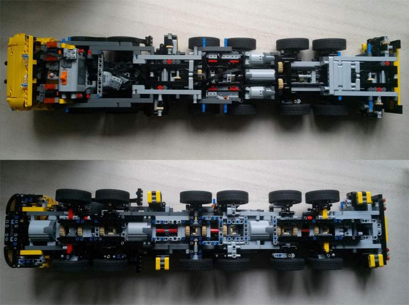
I take away independent suspension and use solid axle. Steering is similar setup as in 42009. i.e. no more wobbly steering. 1st & 6th axles steering rack are 3stud apart from drive axle; 2nd and 5th axles are 4 stud apart, 4th axle is 5 stud apart. 3rd axle is solid axle without steer. I keep the same wheel hub as in 42000 because the wheels are more securely mounted. Let me have some screen capture from the lxf file tonight. I can do a LXF to LDraw conversion again if this modification is worth for the community to update.
-
It is amazing that the project has been on going! So do I for the carrier. After finishing MarkII, I built set 42030 and I feel ashamed that my MOC performance is way under standard lego functions. This caused me to further look into details of each function. I rebuilt the model a few times with different setting and I discovered a critical design issue about single long driving shaft with different turning radius axles. When steering, different axles run at different radius and stress will build up along the driving shaft. After prolonged steering, stress will stack up to a point that it causes the carrier to slow down, gears slipping in differentials and axles twisting + gears damge. It’s lucky that MarkII wobbly steering racks setup has absorbed most of the above issues but it doesn’t help improving the functions. The only solution is to have individual driving motor for each axle. That mean I have to give up MarkII suspension to allow more spaces for motors at different axles. It is a painful decision but worthy to try out. To free up spaces, I use simple solid axles with 3 XL motors for front, middle and rear axles. The overall carrier length is increased by 2 studs. Stress issue is completely gone; driving speed is much faster as XL motors are directly attached to axles without the need of gearing down; steering is smooth and responsive with the help of 2 servo motors. A manual switch between the steering servos is added such that normal steering and crab steering can be selected manually by sync or reverse the servo’s direction; The extra space also allow more gearing down for outriggers to self lifting the whole carrier + superstructure (without extending the outriggers horizontally) ; and enough spaces for double turntable to stabilize the superstructure. When all the above functions added together, I feel like I am playing with a QC tested lego set now. I am still tidying up the cable routing and reattaching the body works and I will create a video update shortly to demonstrate the improvement.

-
wow. amazing! while I am still considering to get a city arctic set 60062 or not, your MOC really attracted me to try one! I don't know how much friction will there be under water, but some technic panels for the rudder blade eg, #64682 , may feel more secure. Just my two cents
-
Good try. There are quite a few 8x8x8 setup without suspension but in compact design. you can google them easily. eg. If this is gonna be BIG style, you may need more torque by adding XL motors in order to keep your carpet test success
-
Although steering geometry is not as ideal as in real cranes, the 1x5L suspension arm + wheel hubs are wobble enough to adopt any angles varies. The real challenge is the very long driving and steering train vs weight. When it steers WITHOUT drive, 1st and 2nd axles turn as always and 4th-6th axles turn less than expected because the superstructure is heavy enough to press the rear part of the carrier not moving. Adding more counterweight to the superstructure may cause the carrier steering worse. All axles steering works fine when it drive. I have some brain storming whether to keep the front and rear drive / steer functions separately, something similar to real grove 12x8x12 arrangement: the front 1st and 2nd axle: - keep 1L motor for steer as where it is now. - keep only 1XL motor for drive and arrange it longitudinally. the rear: - remove 3rd axle gearbox and use that space for second XL motor to drive 4th and 5th axles. 3rd axle will not drive or steer. - remove 6th axle gearbox and use that space for additional L motor to steer 4th, 5th and 6th axles. 6th axle only steer but not drive. A pole switch can also be added to the rear steering motor such that the carrier can preform crab walking mode! There is a big question mark whether the above driving and steering setup can result a more even power distribution along the carrier. But I like current 12x12x12 all wheel drive and steering setup as it is very fun to play with.