
gyenesvi
-
Posts
2,396 -
Joined
-
Last visited
Content Type
Profiles
Forums
Gallery
Everything posted by gyenesvi
-
 This does not seem to have anything to do with non-existent parts that would be good if existed, so it would probably be better in the general parts discussion?
 -
I agree that unfortunately, you are locked to 6L suspension parts, so making a smaller one is hard. But I didn't mean width, I meant longitudinal space. Sure that live axles are better in that respect, allowing you to build narrower driven axles, and to include diff locks. But they take up a lot of longitudinal space and also require quite a lot of space upwards, which makes it harder to build a tight solid chassis around them. Yet still, I prefer live axles, especially for slow vehicles and trucks. Just I had the feeling that building trucks with independent suspension would be kind of cheating and unrealistic (for example in competitions), but this truck shows that at least there is a real world example. For example, this 6x6 truck has 4-wheel steering and probably a small turning radius due to the independent suspension (big plus for trial). That would be really hard to do with a realistic 6x6 truck with live axles, that has the two rear axles further back close to each other. Even driving both (non-steered) rear axles is non-trivial if you don't want to couple them in a simplistic way.
-
What do you mean? In a big model there's more space, and independent suspension takes maybe the least space of all, typically the easiest to implement in lego.. This would have been really hard with live axles, maybe with pendular ones. That's why this model is interesting, I actually wondered if there are real trucks out there with independent suspension.
-
Thanks for the info on that Zil, that's a pretty interesting vehicle, indeed it seems like it has independent suspension, based on this photo I found it even seems it has portal axles (the driveshaft seems to be on the top of the wheel hub)
-
This looks really neat and compact! Only thing I wonder if the real truck (at least in the game) has fully independent suspension?
-
You could still share the motors and the idea to connect them in the brushless motors thread..
-
I undertand that the ends of the U-joint can be shorter because of the axle being fixed by a screw, but I don't get how that would solve the problem of the joint colliding with the pinholes when articulated. So the pivot point must still be misaligned I believe.
-
Well, that's exactly where I was going, that they look misaligned on the picture by half a stud. I don't think it's just the images; it is impossible to align them, because then there's no room for the U-joints to articulate. You can try this with lego joints (only moving them half studs out allows them to articulate without collision). That's why these kind of lego hubs are made with CV-joints instead. So given that they have to be misaligned, it needs to be compensated somewhere. If we want to keep the length of the shaft equal to the length of the suspension arms, that would create a half stud offset on the other end next to the diff as well, which would make it hard to position, and half axles would be required. The other option for compensation is shortening the driveshaft with half a stud. That would create the problem of changing distances between shaft and suspension arms upon articulation. Sure, the difference would be small, and only noticeable upon high articulation angles in off-roaders (not in sportscars). But I wonder how that would effect the drive, whether it would result in unwanted friction, since the metal will have less slack and will yield less than the plastic in these king of situations. The length of the U-joint does not really matter, it's the flex point that matters. Or do you mean the axles going out of the U-joint? Actually, moving the pinholes one stud further away could solve the problem. And also would make the suspension build more firm. I'd guess metal parts are most useful in larger, heavier builds, and those typically have suspension arms 5 studs apart, instead of 3.
-
Hmm, is that U-joint offset with half a stud in the wheel hub? Wonder how easy is that to compensate..
-
I wasn't talking about cutting the axle, indeed that's rounded anyway in reality and the situation is even better than on the renders. Rather, I was talking about having an axle hole at the top where the bottom corner of the surrounding material is chipped off, like in the images. Which, when designing a new special piece, is a viable option :)
-
I had some interesting findings today regarding the towball axle piece. For one, the axle part is a little bit shorter than on the axle-pin (it shows both virtually and I confirmed it on real parts). Second, the collar on the towball axle lifts it a little bit if inserted into an axle hole. This can give extra clearance above the piece, which can be useful for our hub constructions. For example, if it was mounted above a U-joint like this. Then the space up to the towball axle would look like this, allowing the U-joint to articulate up to 25 degrees before touching the axle. So if the corner of the towball axle mount was chipped off like this then the joint would have enough clearance to articulate upwards; 25 degrees would be pretty much enough for an IFS portal. So based on all this, I have designed a simpler, updated version of the currently existing lego portal hub. This is much more simple than the main one in this thread; it would only support U-joints, and would not support kingpin axis, only vertical. However, there are two key differences wrt the existing lego portal. The top part is cut off, and the top reinforcement goes around the top gear (like in the main design, but an axle hole mount is used at the top instead of a fixed towball) The wheel hub insert itself is 1 stud shorter. It would use a similar click-in technique as the currently existing one. I think the shortening would not be a big deal, because of the through axle supporting the wheel as well in case of the portal (as opposed to a regular wheel hub). Because of these, it would fit into the Defender rim and the pivot point would get as close to the wheel as possible (2 studs closer than with the current one). The advantage of the axle-hole top mount is that in case of solid axles, there is no need to use a towball, which makes the axle build much more simple. Here are the ways in which an IFS and a solid axle could be built. In case of the IFS, it would become possible to link the two steering arms, while retaining a max steering angle of 40 degrees! It would look like this with tractor tire. Would already be a substantial improvement over the current one. I think if TLG ever updates the portal hub mold, it could become something like this. Or something completely enclosed based on heavy duty CV joints.. :) I think that may be possible, I have also been thinking how the hub insert could be made better to have less friction and make it more stable. I think where currently the 3 pinholes are next to the 3 pins on the hub insert, there could be 3x 8mm diameter, 4mm thick bearings maybe..
-
I feel that some times too! Glad you like the idea. I guess that day will never come :) The thing is we only need a new part for those things that are impossible to build from the simple ones, due to the inherent limitations of the building system (like discrete sizes and a family of shapes). I don't have them, @Aurorasaurus has, but I'd be curious what you'd like to modify? Any improvement ideas?
-
Well that was materialized fast at the other end of the world :) We've got to appreciate technology! I hope in 10-20 years from now we can just design a piece like that and print it in every home in high quality and strength! Let us know if you make a more polished print and try it in a sketch build! I'm not sure what you would benefit from that, but I agree that being able to swap in 12:20 gearing is also useful, many MOCs use that gearing with the existing portal hub.
-
The problem with raising the pinhole would be that it would be in the way for inserting the 3-pin hub (and maybe also for the 24T gear) from the back.
-
That's an interesting use case, good to know. Btw, a 2L axle would also be useful for connecting two connectors with axle holes in a way that they can be rotated on each other not only by multiplies of 90 degrees. Yeah, I remember those times as well :) And sure, I'd be okay with doing that too with rigid hoses!
-
Well it's obviously too big for 43 mm rims (any design would be too big for that as you cannot fit a 5L liftarm inside, and hence no regular gear mesh would fit inside), it's designed for Defender rims. But it could work with regular 56mm rims, it would be possible to make room for the 0.5L protrusion in the center of the wheel hub, but it would be pretty pointless as you would loose the whole point of getting close to the wheel with the steering pivot.
-
Cool, I've added a part file for the updated frame as well in the main post!
-
I know this part exists, but as you write, it is useless for the purpose of connecting two pins (for example a towball pin to a half pin), because the middle section is in the way. Yeah, cutting the rigid hose is an option, but then I might as well cut a 3L bar to 2L :) Though not sure if cutting the hose is considered "more" legal :)
-
Just remembered that when I was building the G-wagon, it seemed like it could have used this piece with a 1L bar in quite a few places. It uses this piece but half of the bar sticks out in many uses (and looks a bit ugly). Even better, it would be good if a 2L bar existed and we could just make that piece up..
-
Upon consulting with @Attika we considered that the bottom part may need extra reinforcement as the mounting of the lower towball is quite indirect and relies on axle friction and hence not rock solid and may result in some flex and ultimately tilting of the wheel. So here is a possible solution to that, adding a pinhole to the bottom. And here's how it could be built up. To be clean solution, the kingpin variant would benefit from having a towball pin with 2L pin end (would be a very useful part in many other situations as well). For now, a possible solution is adding a half pin and connecting them with a 3L bar (which just stays clear of the rim/tire). Why on earth doesn't even a 2L bar exist..? Thanks, that's a good idea for adding in the towball in case of printing! You might be right, and it's just getting more complex :) Anyways, even if weak, a printed version may be useful just for testing out the geometry in a manual build and not stressing it too much.
-
I can share the Studio part files (added links to the main post), but I cannot make the 3d printable version, and that would require some adjustments I guess. Also, the insert would be better to print without the pins, only 6 pinholes, and add in lego pins.
-
I think they all come from the same manufacturer, everybody is just reselling them. AliExpress may be the cheapest, that's where I got mine.
-
No, in this regard, it has the same geometry as existing lego hubs. However, there's an interesting difference which might be important, because it may be that you could get away without connecting the two steering arms: as opposed to standard hubs, here both arms are connected to the hub from the bottom, the towball facing up. Hence, the lower one cannot disconnect downwards, only upwards, which is less likely I think. For example, if you attach springs to the bottom arm, the force of the spring cannot push it apart, because of the bottom support.
-
When going into RC electronics, I think it is worth separating whether you'd like to just use RC stuff for control, or whether you also want to use non-lego motors. Because Lego and Buwizz motors can also be controlled with RC electronics, and that may be an easier start, as the hardest part is mounting the non-lego motor into lego builds. However, there's a small catch for transitioning later to these RC motors: lego motors are brushed, and the above motors are brushless, and they require different ESCs (or very expensive high end ones capable of controlling both). I think for transmitter/receiver Dumbo RC seems like an affordable and good enough start. You might also want to get some GeekServos for steering/gearbox control, because they are better than Lego servos and it would be more complicated to control them anyway (would require another ESC). With RC receiver it is trivial to control them.
-
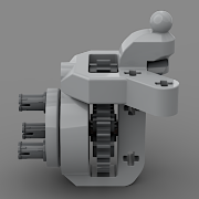
For the eager ones, Studio part files are here: frame and insert. Hello Technic Builders! The existing technic portal hub was a nice piece at the time, but it was designed long ago before the existence of deeper rims (Defender) and it is unfortunately not really compatible with them in the sense that it cannot make use of the extra space (does not fit inside). Unfortunately, when used with regular rims, the current portal hub piece has a horrible steering geometry (huge scrub radius), as it sticks too much out of the wheel, and also takes away a lot of space from the center of the axle build (less room for springs, links, etc). In the past few years I learned a lot about realistic suspension geometry and the ways they are achieved (it turns out that kingpin axis inclination is essential for realistic portal hubs, as the upper pivot point must be outside of the wheel since it is lifted up). So lately I have been lamenting on what could be achieved with a better lego portal hub designs? How well could real-life portals be approximated in lego? This thread is about my findings and design for such a piece. First off, let's list what I'd expect from an ideal portal hub: Requirements it should be symmetric, so that only one piece is required for left/right side it should have a 3-pin rim mount (otherwise we can just brick-build something with a bare axle) it should accommodate 8:24, 12:20 and 16:16 gear ratios (even though the 16:16 does not fit into the Defender rim, there might be bigger deep rims out there, like the Ferrari one or future ones) it should accommodate both U-joints and heavy duty CV-joints. In case of U-joints, it should support a steering angle up to 45 degrees (the joint itself should not collide) it should be usable both in solid axles and in independent suspension (the joint should not collide even in case of up/down angled steering arms) the steering pivot should be as close to the wheel as possible (in case of vertical kingpin axis) it should support building an angled (non-vertical) kingpin axis, moving the steering pivot inside the wheel it should be easy to build a non-steered variant as well That sounds like a lot to ask for. Good news is, that the above piece could satisfy all these criteria! :) Let's see how it works! Basic design features The hub consists of two pieces: a frame and a wheel hub insert with 3 pins (1 stud thick without pins). The hub itself can be inserted from the inside, and it has a ridge to hold it agains the frame to prevent it from being pulled out (the idea is taken from @efferman's design, but my frame designs allows the integration of the pins while still having space to insert the hub piece). The hub insert does not click into the frame like in case of regular lego hubs; this is useful as it can be taken apart for cleaning / greasing. A key design in the frame is to let the whole bottom part be buildable to allow for many options. The piece incorporates the parts that are impossible to build due to the tight space, like the top mounting point and the frame around the gears. In order to allow for independent suspension and give space for heavy duty CV joints as well, the top mounting point is fixed to be a towball. Such requirements would be impossible to achieve with a regular pin, as the pin would collide with the joint. But with the past introduction of planetary and Audi hubs, the integrated towball is an established practise for lego wheel hubs, so this piece uses the same technique. Hopefully more towball socket pieces will follow to allow for more mounting options.. Finally, the frame adds mounting points for connecting the lower steering arm and the steering links. This is done with minimal extra material and with care to leave space for the joints. Of course, the exact shaping of the part can be polished, some edges could be rounded off, and some extra support bits can be added where it is needed. But the overall shape and mounting points are there, this is how I could easily model it in Studio Part Designer. Gear and joint assembly To assemble the gears, one more piece is required to close the gear housing from the back. A key feature of the frame is to allow for two options (5L thin beam and 5x3 thin T beam), resulting in two possible pivot positions in case of U-joints. In the outer position (aligned vertically with the upper steering pivot), the upper gear is supported from two sides, half a stud on each side. In the inner position (half a stud more into the wheel), the upper gear is held by a full stud of mounting on the outside (as in case of the existing lego portal hub). In case of heavy duty CV joint, the same two positions are available, with even more support (always on both sides of the upper gear), and an extra support piece can be added right next to the joint head. In all cases, there's space for more than 45 degrees of steering angle (if the joints allow), and more than 25 degrees of suspension angle. The outer joint positions (aligned with the upper mounting pivot) can be used to build vertical kingpin axis geometry, while the inner joint positions where the joint pivot is half stud more into the wheel than the upper mounting pivot can be used to build a tilted kingpin axis geometry. In this case, the lower mounting point will have to be one stud more outwards (into the wheel) than the upper one, and the joint will be exactly in line with the kingpin axis halfway between the two mounting points, like this Mounting the steering arms / examples The only thing left is building the mounting point for the lower steering arm. There is a lot of space, and there are plenty of options, here are a few examples. Here's a basic way to connect the top and bottom part of the frame with extra pieces, adding mounting point for a towball or pin at the bottom, both in an outer and in an inner position (U-joint could also be used as above). Here's how it could be used in a solid axle (steered and non-steered version): Here's an example for a (non-steered) independent rear suspension (in that case, the upper and lower mounting points can simply be aligned, no need for kingpin inclination): And here's how the most complex one, and independent front suspension with kingpin inclination could be built. The same can be used for a solid axle with kingpin inclination, in that case the steering arms would not be angled but would be fixed to horizontal. Note, the mounting position of a the steering link. In this height it is in line with the kingpin axis, so there is no ackermann geometry. If however, we move the steering two studs lower, like below, then we can achieve ackermann or anti-ackermann geometry because of the half stud distance to the kingpin axis at that lower position. Here's how it would look with rim and large tractor tire on And here's an image showing the kingpin axis from the front One more note about suspension geometry. By making the lower suspension arm 1 stud longer in the above IFS example (aligned pivot points next to the differential), it is possible to implement changing camber angle (tilting of the wheel). In this case the top of the wheel would tilt inwards, when the steering arms are not in a horizontal position. This could work well for faster buggies when the resting position of the arms is close to horizontal, and when the wheel moves upwards, it would tilt inward at the top (relative to the chassis), keeping the wheel horizontal during fast cornering (when the body tilts outwards). Compensating half stud offsets of joints One additional difficulty about building the kingpin variants is that the joint will the be on a half stud offset relative to all other parts and that needs to be compensated somewhere. It's not trivial with the available lego parts, but there are some options: The 5.5 stud long axle can be used in case of solid axles where the with permits The old CV joint male part has a 1.5 stud deep hole in it. That can be used in case of an IFS or even in case of a solid axle, as a straight axle joiner. It is not a big problem that this old CV joint is weaker, because it is only used in the front axle, and only on the inside next to the differential, where there is less stress on it. In cases where there is independent left-right drive, there may be space for an extra half stud of axle in the center of the suspension axle In less stressful applications, a 2L axle with a half bush in the middle, leaving 3/4 studs on both ends could also be used to connect two joints. I've tried it, feels solid enough by hand :) Updated variant with extra lower mounting point Studio part file. Let me know what you think of all this, if you see any problems or possible improvements! For virtual testing, here are the Studio part files: frame and insert. Anybody wants to try and make a printable version of it? And of course, should Lego make such a piece? Cheers, Viktor