
Hod Carrier
-
Posts
1,001 -
Joined
-
Last visited
6 Followers


About Hod Carrier

Recent Profile Visitors
10,039 profile views
.thumb.jpg.ce80d68d9be64aea52e2c3eabf9f3075.jpg)

-
[Virtual MOC] Stadler Flirt UK - TfW Class 231
Hod Carrier replied to Hod Carrier's topic in LEGO Train Tech
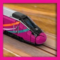
Forgive the boost, but I've been tinkering on and off with the Flirt. Initially this was to address concerns about it's structural integrity, but I thought I'd also have another go at addressing some of the design choices I had made with the original design. Most of this is around the driver's cab, as can be seen by this side-by-side comparison. One of the biggest errors was the angle of the windscreen, which I had made too steep. Some newer parts have helped me to get a smoother shape, although one or two cheats are needed to get the shape shown here. The cab now has a more curved profile that more accurately follows the shape of the real train. I've also addressed the side window, which would require a custom made sticker or printed parts. The head-on view makes the new design look a little bit too wide, but it's about as close as I can make it. On the positive side, the shape of the lights are nearer to the real train than the previous version. While I've been tinkering, I took the chance to use more recent pictures to correct the roof of the power pod. Unlike the diesel-electric Class 231 which has four diesel motor-generator units (MGUs), the Class 756 is a tri-mode train that operates mostly as a battery-electric train and has only one MGU. This means that the roof details are different, which I've replicated here. I'm still not sure about whether or not this model will ever get built. The idea for power and control was to have some manner of smart brick hidden in the power pod with wiring through the train for lighting, etc, but it seems that the state of third party supply has taken something of a dip. The ideal was the PFx Brick with a matching light board, but it seems that the focus on their track system has meant that the Brick has fallen off the table. It may be that the only option will be BuWizz, but it's expensive and not really ideal for my needs. Either way, here is the model as a virtual design at least. -
You've been on quite a journey, but it's been totally worth it. I'm really glad that you've got it finished and are happy with the result. It's a testament to your determination. Congratulations!!
-
Oh no, I'm far too long in the tooth now to consider a career change. I'm happy just tinkering with LEGO.
-
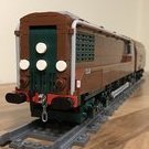
As we say in the UK, there's always more than one way to skin a cat and, as someone whose garden has become some form of communal feline latrine, I'm always keen to uncover new ideas and ways to tackle a problem. ...but that's just me. @Ferro-Friki: I must congratulate you on your chassis design. Her Ladyship is a bit of a whopper and the bogies are quite far apart, but when I looked at the photos you'd posted I estimated that, with the amount of lateral movement you had given to the middle bogie, the outer bogies were likely to need only around half a stud of movement to be able to fit around an R40 curve. So I built a basic chassis using the same dimensions and layout to test the theory, and so it proved (just)!! It's a wee bit tight, but there is just enough movement to get her to sit nicely on an R40. As to the articulation, I'd had a very simple idea based on visualising what would happen with three bogies linked together with bars travelling around a layout. I'll admit that I wasn't hugely confident that such a simple idea would work, but I added a set of levers and pivots to the chassis and away she went. I set up some curves, straights and points/switches and hand-pushed the chassis around it, and it seems to work fine. The problem was always going to be how to centre the loco again after coming out of a bend onto a straight, but the levers take care of it admirably. This configuration should work fine for your model, although the position of the pivots can be moved to change how much each bogie will move relative to the others to suit other models. I'm unsure how you might want to incorporate this into your design, or even if it would be suitable. I know how little space you have inside the loco body, but it might still be possible.
-
Firstly, huge admiration for crafting a wonderful loco so full of detail and so faithful to the original. Loving your commitment to the curvature. I have given some thought to the B-B-B arrangement in the past and how it might be made to work with the track geometry we are given, and I came up to the inescapable conclusion that it wouldn't be enough just to articulate the middle bogie. You'd have to articulate all three. The problem with this is that you would need some kind of internal linkage to ensure that the loco stays straight, and that might mean space inside the loco body becomes a premium. Given that you have already designed and built your wonderful engine, this would unavoidably mean a wholesale re-engineering. There is a concept in my head that needs to be refined and tested, but I don't have much time at present to work on it. However, if you'd like, I can see what I can come up with which might help in your quest to run Her Majesty wherever you wish.
-
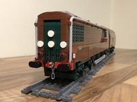
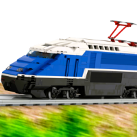
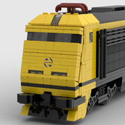
You may be interested to know that "The Badger", as the loco is affectionately known, still exists. I drove past it just today at Crewe. Your model is a very good likeness and immediately recognisable. Just one small observation, if I may. The pantograph is facing the wrong way and needs flipping around so that the elbow points towards the centre of the loco.
-
I'd just like to add my own thanks and appreciation for your time, effort and devotion. I wish you every success with whatever direction you take next.
-
Custom decals/printing: where to start?
Hod Carrier replied to TeddytheSpoon's topic in LEGO Train Tech
I always think that if you're building a model of something real it would be good to include at least some of the more obvious markings and other decorations. How far down this particular "rabbit hole" you want to fall is entirely up to you, but I do think that a loco should have it's number and the railway's identifying crest/logo. Printing onto bricks is the Rolls Royce solution for getting logos, numbers and other decoration onto parts, but it is permanent and a bit pricey. May I recommend a couple of alternatives...? An option that I've made use of is printing my own graphics at home and then applying them to the finished model. Design and scale them on your computer and then print them onto self-adhesive inkjet vinyl (available in A4 sheets of white or transparent from retailers such as this one). Just a couple of tips with this technique. Leave the sheets for a few minutes after printing to dry before handling and then seal the print with some spray-on craft sealer before cutting and sticking. As well as the sealer you should also get a selection of Sharpies in different colours, as the white edge of the stickers will still be visible and may need to be coloured-in before applying them to the model. If you want to try to match your stickers to the colour of LEGO bricks, Rebrickable has this useful guide giving you the RGB code for each colour, although bear in mind that there can be quite a bit of colour variation between individual parts of the same colour and that your printer may not necessarily replicate the desired colour perfectly. The other option is to use waterslide transfers. Most LEGO train models are tolerably close to UK 7mm scale/O-gauge (a scale of 1:43.5) and you can buy sheets of crests, numbers, markings and lining that you can apply directly to your model. For British models, like your Ivatt 2MT, a retailer like Fox Transfers should be able to provide all your needs. Hope this helps. -
I've done something along similar lines, although not exactly the same thing. Being primarily a builder of trains, I started off using luminous parts to replicate interior and exterior lighting, which has worked out quite well. With the basics covered, I moved on to using them to try and provide realistic lighting for enclosed spaces, much as as you might do for modulars and other similar builds. In my case, I applied the technique to underground and subway stations. One small innovation was to combine luminous parts with custom graphics to provide stencils to replicate illuminated signs. The closest that I have come to using luminous parts out-of-shot to provide a sort of lighting rig was when I fell down a bit of a 2001: A Space Odyssey rabbit-hole and created some artwork pastiches. Replicating some of the lighting effects from the original film poster (the lighting of the space station and the reflections on the helmet visor) required luminous parts in various configurations. As well as the original film poster pastiche, I recreated a couple of artworks released to commemorate the 50th anniversary of the release of the film that required the use of luminous parts. These included an alternative poster featuring the famous corridor scene in which the lighting is provided by luminous parts in-shot, and my version of the Dave O'Flanaghan Monolith scene on the lunar surface. One thing that I have struggled with is just how shiny the surface of regular parts are when rendered, forcing me to make heavy use of the rubber colours palette to create matt surfaces that wouldn't simply reflect everything like a mirror. Part of this might have been due to how close the parts were to the light source (e.g. in the London Underground scene) and also because I was trying to light a scene rather than a single MOC. Whatever the case, it looks as though you've not been hindered by any such problems enabling you to get some great results using this technique. Your renders certainly look a lot richer as a consequence of the interplay of light and shade that you've been able to achieve compared to the slightly less interesting results the standard lighting creates. I will certainly be looking into this a bit more as a result of your ideas. Thanks so much for sharing.
-
[MOC] 2-axle passenger wagon in 1/32 scale (gauge 1)
Hod Carrier replied to Sven J's topic in LEGO Train Tech
I investigated this issue a few years ago and there is quite a long thread detailing the process. I don't necessarily recommend you read the whole thing (unless it particularly interests you), but you can read my summary here. -
Thanks folks. I'm not sure how buildable this design would be, as it uses a whole hill of SNOT (and I really doubt it would be strong enough to support a pot plant). I've spent a lot of time looking at it and fiddling with it and I'm still unsure about it. I had an idea about powering it, but that also is still just an unproven idea. I don't release instructions or files but am happy to share techniques. The track has sleepers/ties and ballasting using conventional methods with an added 3rd and 4th rail using clip tiles and flex tube.
-
Interesting. Not sure how many people are sticking to the part limit, but might be worth a tickle.
-
BBCode has been disabled, but you can still embed Flickr content by following the instructions in this post. Click Nice "Chopper", by the way. Good to see some triple grey.
-
Oops!! My bad. I have flagged the post and asked if it can be moved. In my defence, the descriptor for this board on the forum index does still mention "military" and probably was what stopped me scrolling any further down to find a better home for this thread. Thanks, Dave. Wikipedia are pretty good at listing surviving aircraft, so they may have a better list than me. The only two I am aware of are a complete Mk.X at the RAF Museum in Hendon (free entry) and an Australian Beau that has been under restoration to flying condition for more years than I can recall at the Imperial War Museum in Duxford (admission charges apply).
-
I’ve been a big fan of the Bristol Beaufighter since boyhood and have made several attempts down the years to build one in LEGO. The big Bristol fighter was a compromised design from the beginning and for a long time lived in the shadow of the faster de Havilland Mosquito, but it still managed to carve out its own niche as a potent strike fighter, which endears it to me enormously. In my opinion, the Beaufighter is one of the great unsung heroes of WW2. It was not a fast or pretty aircraft, and most of its exploits were carried out away from the public’s gaze, either in the night skies over Britain, far out over the sea in the North Atlantic or over the dense jungles of the Far East. However, its ruggedness and its ability to land a mighty punch made it an indispensable weapon. Its design may have been compromised from the beginning, but it more than made up for its shortcomings with its abilities. Annoyingly, the Beaufighter is a difficult shape full of LEGO-unfriendly curves and every design I came up with looked wrong or out of proportion, in particular around the nose. In the end I decided to shrink the design down to approximately Microfig scale which seems to have worked relatively well, although I have had to use one or two illegal techniques. It requires a couple of tabs of double-sided tape and some modified parts, in particular around the landing gear and the obvious 2x6 wedge tile on the rear fuselage sides to allow for stickers which would be difficult to apply to a 2x6 wedge plate. So here is my design for the Bristol Beaufighter. I have done some test builds to prove that it is buildable but I am presenting it here as a digital design. I have gone a bit mad and varied the design to depict not only the first prototype but also all five major production marks, although colour availability would mean that only four of these models are actually possible to build. The origins of the Beaufighter go back to the Munich Crisis of 1938 which highlighted the RAF’s need for a heavy long-range fighter. Development of the Westland Whirlwind was delayed, and so Bristol submitted a proposal for a twin-engined cannon fighter based on the Beaufort torpedo bomber that would use some of the same assemblies to speed the production of the type. The result was the Bristol Type 156 “Beaufort Fighter”, a name that was shortened to Beaufighter. The unarmed, unpainted first prototype flew in July 1939 and achieved 335mph, although this came down to 309mph with the second prototype which had operational equipment fitted. Changes were made to help improve aerodynamic efficiency, but concerns remained about performance due to the engines used. The intention had been to use Bristol Hercules VI 14-cylinder radial engines rated at around 1,500hp, but these were still being developed and priority for them was given to the Short Stirling heavy bomber. The model design depicts the first prototype, R2052, in its original configuration with the oil coolers under the engine nacelles (later moved to the wing leading edge) and short landing gear doors that did not fully enclose the main wheels when retracted. The Beaufighter Mk.I went into production using a less powerful version of the Hercules engine than originally intended, but it still packed a mighty punch. Armed with four 20mm cannon in the fuselage and six 0.303in machine guns in the wings, the Beaufighter had the heaviest fixed armament of any aircraft of the time. It was originally intended to be used by RAF Fighter Command as a day fighter, but it’s large size and low speed made it less than ideal in the role. Combined with airborne interception (AI) Mk.III radar the Beaufighter was an ideal night fighter, having the speed to intercept enemy aircraft and the weight of armament to deal a lethal blow. Night fighter squadrons who had been saddled with less effective aircraft, such as the Bristol Blenheim, and were frustrated at being on the sidelines of the Battle of Britain eagerly took to the Beaufighter. Very soon, a number of night fighter pilots had become aces flying the type, including John “Cats Eyes” Cunningham, and night fighter squadrons were soon accounting for more enemy raiders destroyed than ground defences. In addition to its success as a night fighter, the Beaufighter (or “Beau” as it became known to its crews) continued to operate by day against air and ground targets, particularly in the Mediterranean and North Africa where it was used to provide air support to ground troops. Beaufighters were also supplied to RAF Coastal Command for use as long-range strike fighters. Mk.I aircraft were initially built to a common standard and then adapted, but the differing requirements of the two commands meant that they eventually had to be built separately. Coastal Command’s Mk.1C differed from Fighter Command’s Mk.1F by trading the wing-mounted machine guns for additional fuel capacity for increased range, different radio and radio-navigation equipment and no radar. These aircraft performed a variety of operations including long-range fighter patrols as well as strikes against enemy shipping and ground targets. Patrols over the Bay of Biscay and success in destroying long-range bombers operating against allied shipping, such as the Focke-Wulf FW 200 Condor, effectively removed the aerial threat from the Battle of the Atlantic. A single Coastal Command Beaufighter Mk.IC, flown by Flt Lt Ken Gatward and his observer/navigator Sgt George Fern, took part in a daring one aircraft daylight raid on Paris. Codenamed Operation Squabble, Gatward and Fern flew at extremely low level to cross occupied France unopposed. They overflew the Arc de Triomphe and dropped a French Tricolour, continued at rooftop height along the Champs Elysee to strafe the Kreigsmarine headquarters on the Place de la Concorde and drop another Tricolour before escaping again. It was later described as “perhaps the most impudent raid of the war”. Although the Mk.I wore a multitude of different colours, including day fighter and desert camouflage, I have modelled a Mk.IF night fighter in matt black camouflage. I have attempted to include the AI Mk.III radar antennae on the nose and wings of the aircraft. Following the slightly disappointing performance of the Mk.I, the quest to unlock the potential of the Beaufighter continued. The original specification stated that the aircraft should be capable of using either the air-cooled Bristol Hercules radial engine or the liquid-cooled Rolls Royce Griffon vee engine interchangeably. Although a Griffon-engined prototype was flown, this engine, like the Hercules VI, was prioritised for another aircraft and so was unavailable for the Beaufighter. A potential solution came in the form of the Rolls Royce Merlin XX which was being offered in a self-contained “power plant” installation that would be seen again later in the war on the Avro Lancaster. The result was the Beaufighter Mk.IIF. The Beaufighter Mk.IIF was used primarily by Fighter Command as a night fighter. A small number were also delivered to the Royal Navy Fleet Air Arm for use in a variety of secondary roles such as operational training and convoy escort. Although the change in engine did give the Mk.IIF slightly better performance at high altitude compared to the Hercules-powered Mk.I, the Merlins were still insufficiently powerful to improve the overall performance. As well as a lack of power, something about the installation and characteristics of the Merlin XXs on the Mk.IIF exacerbated a problem inherent in the Beaufighter design. Right from the start it was observed that the Beaufighter had a directional instability at low airspeeds. The Mk.IIF in particular could swing violently to port (left) during take-off runs, potentially causing the aircraft to ground loop. This made the Mk.IIF unpopular with crews. Wing Commander Pearson, commanding 600 Squadron, who were one of the first to receive the type, observed that it was “an unnatural and dangerous aeroplane … No matter how the aircraft is trimmed, it will not fly straight and level hands off”, concluding that “the Beaufighter is a great aeroplane; the Merlin a great engine. Together they are a great disaster”. Various solutions were tried, including a taller tail fin and a dorsal fillet, but the designers settled on enlarged tailplanes set at 12 degrees of dihedral for all marks, but only the last Mk.IIFs built received this design of tailplane. Of around 450 Mk.IIFs built, around one third would be lost in accidents, and by mid-1942 the Mk.IIF was withdrawn from frontline service and relegated to secondary duties. My model of the Mk.IIF is in night fighter matt black, which is the role that the majority of these aircraft undertook. The big difference is in the shape of the engine nacelles. A change by RAF Bomber Command in aircraft procurement meant that the Short Stirling was no longer in demand and the Hercules VI engine could now be made available. At last, the Beaufighter would receive the power that it was always intended to have. The Beaufighter Mk.VI was, like the Mk.I, built to two different specifications as the Mk.VIF for Fighter Command and Mk.VIC for Coastal Command. As before, Fighter Command would initially use the Mk.VIF as a night fighter, although they would eventually transition to the de Havilland Mosquito for home defence. However, it would continue in the role in other theatres of operation, including with the USAAF in the Mediterranean and Italy. Once again, it would be Coastal Command who would put the Mk.VIC to best use. The additional power meant that the aircraft could now lift external weapons including bombs, rockets and even air-dropped torpedoes. Squadrons would be formed into Wings operating out of strategically located airfields so that they could operate in large formations of rocket or torpedo armed aircraft to harass enemy shipping from the Bay of Biscay to the Norwegian Fjords. I have adapted the design to show a Coastal Command Mk.VIC in the short-lived white and grey scheme with rocket rails under each wing. The tailplanes have the now standard 12 degrees of dihedral. Eventually, with Fighter Command’s interest in the Beaufighter waning, Bristol would offer Coastal Command a bespoke low-altitude strike fighter specifically suited for low-level attacks on shipping and land targets, the TF Mk.X. With the Hercules engines now producing 1,750hp each at 500 feet, the TF Mk.X was equipped with ASV radar to search for shipping and could carry an air-dropped torpedo. The “Torbeau”, as it became known, also provided rear defence in the shape of a Vickers K gun at the observer’s position. Initial versions looked similar to the preceding Mk.VI, but the TF Mk.X was later equipped with updated ASV radar in a thimble radome and the dorsal fillet first trialled on the Mk.IIF to aid directional stability. Alongside the TF Mk.X, Coastal Command received the Mk.XIC, which was identical to the TF Mk.X but was armed with rockets instead of a torpedo, which became known as “Rockbeaus”. These would be the definitive versions of the Beaufighter. This model shows the final iteration of the TF Mk.X with thimble radome, dorsal fillet and Vickers K gun for the observer. Air-dropped torpedoes had a plywood aerodynamic tail to ensure that they entered the water in the correct attitude. This would break off when they hit the surface of the water. The abilities of the Beaufighter as a strike fighter meant that, as well as serving in the war against Germany and Italy, it also served in the Far East and Pacific against the Japanese. The RAF were using the type over the jungles of Burma and South-East Asia while the Australian RAAF were operating Beaufighters in defence of New Guinea and other territories adjacent to their northern borders. One of the most notable actions in this theatre of operation was the Battle of the Bismark Sea, in which Australian Beaufighters flew in support of Australian and American bombers and torpedo bombers against a large Japanese troop convoy. The RAAF received British-built Beaufighters of various marks (all of which appear to have been confusingly classified as Mk.IC irrespective of their specification) but soon the type was being built under licence in Australia. This version was classified as Mk.21 and was broadly equivalent to the Mk.VIC, although local operating conditions meant that the precise nature of the equipment and armaments carried could vary. These Australian-built aircraft became known as DAP Beaufighters, after the Department of Aircraft Production in Melbourne that built them. This model of a Mk.21 DAP Beaufighter is in overall dark green as used by the RAAF with SEAC roundels to aid identification of friendly and hostile aircraft.