arik
-
Posts
72 -
Joined
-
Last visited
Content Type
Profiles
Forums
Gallery
Everything posted by arik
-
3 Speed linear Gearbox
arik replied to SNIPE's topic in LEGO Technic, Mindstorms, Model Team and Scale Modeling
Hmm the idea is nice, but I don't think it will work too well this way. The motor will be fighting against the clutch gear when in the central position. I think you'll need at least two driving rings (or moving axles). -
Thanks all. The catch/switch combo works nicely as long as you remember to turn the switch all the way and not stop already when the motor starts spinning. It looks like it might not get all the way into the transmission ring, but at least here it works nicely (not very high torque). I wanted to have an air tank so that the functions can be used without constantly running the motor (especially as my 2 year old son likes to play with the truck). Then again filling the tank takes long time with only one pump, so another is a must. Also using the large cylinders quickly depletes the air pressure. So yeah, the reason is to get the tank filled quicker. I don't think dual pump would affect max pressure. I've been contemplating adding an air tank override switch to the system. The simplest way would be to have the tank in a separate T-branch behind a switch (i.e. connected only with one tube). It would also allow pressure release. But I don't know whether an air tank works well with only one tube and running compressor (the other end blocked, obviously). Thanks. The tank isn't needed if running the compressor at all times, but it's nice to have. :-) I hate it when the pressure builds up too much and strains the motor (and the pump I guess). The only advantage using LA in this model is control of the height of the boom (which of course gets ridicuously high). Maybe it could be simulated using pneumatic cylinders in sequence... Having completed the build I noticed one problem. I geared down the winch quite a bit (maybe half the speed from original model), so now it is maybe too difficult to unwind. I'll probably need to redesign it with fewer gears and/or less gearing down.
-
Hi, I'd like to present my mod of the 42008 Service Truck. We've seen the excellent all-PF mod by Arachnid, but I took a completely different route: all-pneumatic functions! :-) To summarize, the modifications were: - pneumatic outriggers (instead of mini-LAs) - pneumatic boom raising/lowering (instead of large LA) - dual air pump, located at the side - switch for engaging compressor or hook winch (run by the M motor), located at the other side - air tank - lights at the top All four pneumatic switches are located at the top of the vehicle, plus winch release lever in the original place, making it easy to operate functions. I think this improves playability considerably. Hook can be wound with the 6th lever on the left side of the vehicle. The same lever is used to engage the compressor, which doesn't need to be running at all times because of the air tank. In the original model the boom raises way too high, but it is non-issue as the LA can be extended only little as needed. Pneumatic cylinder is much more difficult in this respect, so I decided to use only part of the range of movement, so the boom is either lowered or raised to a reasonable height. Of course this is easy to modify if needed. I relocated the pump to make room for the air tank, but mostly because I like to watch it operating. :-) Also there's now shorter route from motor to it. As there are now four large and two small pneumatic cylinders, I felt a single pump wouldn't be sufficient, so I came up with design for dual pump setup. Having them run side-by side in opposite phases would have taken too much space, so I set them up counter-rotating in the same plane. Even though the pumps are supported only from one side, it doesn't appear to be a problem. I wanted to have the compressor and winch under the same switch (there's really no reason to operate both at the same time). I connected the changeover catch and PF switch with the same axle, so the motor is only engaged when either gears are engaged. This also ensures the winch is wound only in one direction (given that battery box switch is in correct position). I don't know if this is 'legal' or not (if the angles for co catch and pf switch are the same), but appears to work nicely. Video here: https://flic.kr/p/oPKXvM (ignore crappy audio) I'll be making an LDD model of this later on (possibly improving the design here and there), so stay tuned if interested. Thanks for reading, comments are appreciated!
-
Very good entries indeed, very difficult to choose the best. Here we go: 3: 1 6: 2 11: 1 12: 2 21: 2 22: 2 29: 1 31: 2 39: 2 40: 2 46: 1 51: 1 54: 1
-
Actually I think it needs some support to keep from spinning when either of the axles is turned. I suppose it shouldn't be too hard to do by replacing either of the 2M beams with a longer one so that its other end is between other parts of the structure. Also having the input and output axles aligned is possible, but then we're back to a rather complex structure.
-
Would the new sliding red 8t gear (which I have none so far) work for this? Some thing like this:
-
[HELP] 9398 4x4 Crawler Steering
arik replied to Stingroo's topic in LEGO Technic, Mindstorms, Model Team and Scale Modeling
Btw how common is it that when reset, a servo motor doesn't perfectly align the dots vertically? Mine doesn't, so the gear rack isn't centered with a 12t gear. (But the difference is less than one tooth in the gear.) It's noticeable when driving around, not only with 9398 of course. Hm, maybe adding one extra 12t gear somewhere might help with this... -
8052 container truck hook mechanism
arik replied to arik's topic in LEGO Technic, Mindstorms, Model Team and Scale Modeling
Solved! Not surprisingly, it was my mistake... A misplaced half-pin that prevented the hook arm extending fully. Thanks for the help! (I just knew that I would find the problem as soon as I posted this...) -
Hi, I've just built 8052 from parts from other sets, mostly according to instructions. I had to change a couple of details, but nothing functional, except substituting the 24t gear with the white clutch gear. However, when I unload and load the container from/to the truck using the clever hook mechanism, the hook doesn't get sufficiently low for easily attaching or detaching the container. It stays maybe one stud too high. If gently pressed down, it can slide under the container attachment point. Do you have the same problem? It's not a big issue, but I've seen a YouTube video where the truck just unloads the container and then "drives" away. I was sure there was some kind of mistake when building the truck, but I cannot spot it. The only thing I can think of is if the linear actuator behaves differently: if it only extended a couple mm longer, it would be fine. Surely the clutch gear cannot be the reason? (Now the LA internal clutch doesn't engage, but I don't think correct operation of the model would depend on that...) If this not a common problem, maybe I should post a pic or two, if you can spot the error/reason...
-
[HELP] Pneumatic Walker
arik replied to Zerobricks's topic in LEGO Technic, Mindstorms, Model Team and Scale Modeling
That's interesting! I've been thinking of building a four leg walker myself, and found it much harder than six legged. Basically you can either move the legs in opposite pairs (like a lizard), or move legs up and forward one at a time. Instead of keeping the other legs stationary as in the video above, I think the most realistic way would be to move the other three legs 1/3 of the speed back, keeping up continuous gait. But I don't think it will be simple to do either mechanically or pneumatically. (I'm sure I'll try to build a mechnical one anyway some day.) Did you have a gait pattern already in mind? Oh and the leg design looks very nice! Any chance to get a video of it? -
1. For steering, chaning friction pins to axles and leaving out the half pins helps a bit. 2. I've not moved the battery box, but using the crane stabilizers and keeping crane turned sideways facing away from pneumatic controls helps it keep it straight. (Also note that turning the wheels will cause leaning.) For other issues, I've done these small modifications: - I've run the electric cable near the center diff using a black pin so it's not loose. - I've added an air tank under the bed (but then you can't add a motor for drive). - I've changed gear ratio at portal axles to 1:3, it makes the fake engine run faster and of course is good for motorization. - Also a pole reverser switch is useful addition (although I don't have one installed at the moment) For a "bigger" change, I've changed the grabber to the one from 42006 Excavator, of course changing it to pneumatic. (I think there was discussion about it some time ago here, but I made my own version. I could share if I find time to do a LXF of it.)
-
Hi all, I'd like to share my pneumatic tail lift design. Lowered and tipped down. Raised. Closed. It's now 15 studs wide (can easily be made wider but not much narrower) and will fit to vehicle that has bed at 10 or 11 studs high from ground. As pneumatic cylinders are 7 .. 10.5 studs long, I had to make the static arm just over 7 studs long in order to be able to tip the platform down slightly. Also the air hose nozzles had to face upwards for ground clearance, so the black arm needs to make a 90 degree angle to leave room for tubes. The lift is powerful enough, and as always with pneumatics, you have to be careful operating it, particularly tipping the platform up and down. I'm not terribly pleased with the platform, as it is of even width, and so you can't really have a large panel there without breaking symmetry. Here's a video of it. The red beams represent the body of a vehicle, grey ones holding them just supporting elements. Here's the LDD file. (Don't pay attention to pins and axles in the platform, they're not realistic.) I hope you find the design useful for your own creations. Any improvement ideas are warmly welcome (especially regarding the platform)! BR, Ari
-
I also completed building this yesterday, and have to agree this is a spectacular moc! Haven't yet fitted a Barbie for it from my daughters' collection, though. Was there somewhere updated instructions for the current 9398 parts set, meaning building it with only 28 cross blocks (6536) instead of 30? (2 of them got replaced with another 90 degree connector in 9398.)
-
Gee's General Newbie Topic
arik replied to Gee's topic in LEGO Technic, Mindstorms, Model Team and Scale Modeling
I still think there might be extra friction or faulty parts somewhere. It should be able to lift small weight (maybe around 100g?) easily, definitely more than a couple of bricks. Speaking of the clutch gear, I think it kicks in too early. I've understood (not tested myself) that it starts to slip at 2,5-5 Ncm, while M motor torque is around 4 Ncm (?). So having gear reduction 3:1 between motor and the clutch gear means it starts slipping already when the motor is delivering 1-2 Ncm, or 25-50% of what it is capable of. I think the gear reduction should be after the clutch gear, if needed at all. -
Gee's General Newbie Topic
arik replied to Gee's topic in LEGO Technic, Mindstorms, Model Team and Scale Modeling
That's quite fast building! It took me much longer. (But I came out of my dark ages only less than a year ago, 42006 being the first set for me.) But actually you might want to check your gearbox and other power transmission to the grabber. I recently de-motorized it and even my 2 year old son could operate the grabber with his tiny fingers, there's not much resistance. Just make sure not to squeeze gears against liftarms, as it will cause quite a bit of friction. + Ari -
[HELP] Gear Ratios
arik replied to SNIPE's topic in LEGO Technic, Mindstorms, Model Team and Scale Modeling
Yes, but regardless of the idler gear. You get the same ratio whether you connect with the idler or the gear driving the idler. Nice design nevertheless. -
[HELP] Gear Ratios
arik replied to SNIPE's topic in LEGO Technic, Mindstorms, Model Team and Scale Modeling
As the idler gear doesn't rotate any axle, I'm not sure it makes sense to calculate gear ratio for it. You would drive yet another gear with the idler, so that would define the gear ratio. If you'd drive a 8 tooth gear with the 24t idler (driven by 8t and 2x 16t), it'd be 1:1 ratio. Driving a 24t would make it 3:1, right? As far as I understand, the idler gears do not contribute to the gear ratio (only direction possibly). -
I put an L motor from 9398 to Unimog (under the bed) just a couple of days ago and it works quite well. Did you remember gear down the portal axles (3:1)? With that it's still quite fast (certainly not a crawler) and cannot climb much. I'm planning to put 25:9 gearing to the rear (will leave room in front for the servo, and I'm also avoiding putting too much torque to the universal joints there). The central diff should take care of speed / torque distribution, right? Of course XL would have more power (and maybe no need for gearing it further down?).
-
2: 4 11: 3 22: 3
-
Thanks! It seems I can't register to Brickshelf, but here goes a few pictures I put to Flickr:
-
Thanks. I only came across one Unimog having a tail lift, but as far as I recall there weren't any decent pictures of it. But at least one exists ;-) A box covering the bed would definitely be good, as it would also allow for a longer lift part. Now it can't be any longer without looking silly with the open bed. Will have to wait some time before I dare to suggest to the wife I'd get some more sets ("for the son", 1 year old ;-). + Ari
-
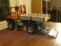
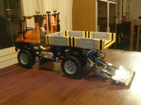
Hi all! I'm new to this forum and also to building Technic since my dark ages. I've only got the Excavator 42006, Unimog 8110 and Power Functions pack, and decided to try building something for the Unimog. I haven't seen anyone done a tail lift for the Unimog so here it goes: (Sorry for bad photo quality but it appears I have strict size limits as a new member.) It took quite a bit trying to get the geometry right, and having such a limited set of parts (8110 arm and 42006 excavator), I had to do this with a combination of pneumatics and linear actuators (would have preferred just pneumatics). The bed of the Unimog is very high for a tail lift, so the lift arm needs to be long. Luckily a 15M beam was just enough for it. Also the bed needed to be extended by about 8 studs, which doesn't look very pretty but is ok I think. (Bee coloring is of course due to limitations with the parts available :-) The tail lift is a separate module but cannot be attached as a normal rear attachments. To minimize the extra length needed for the bed, I removed the rear bumber and the attachment point and moved PTO a couple of studs towards the front. The tail lift module is secured by wrapping a 9x5 frame around the four beam ends from the vehicle. I also added some reinforcements for the beams to keep them from bending too much. I tried also Lego Digital Designer and modeled the tail lift and extended bed with it, primarily just for myself so that I remember how to build it later on :-) Here are the lxf files (I used pneumatics and LA parts from this forum, thanks!): Tail Lift.lxfExtended Bed for Tail Lift.lxf Any comments are welcome, and if you find improvement ideas or a nice way to add the rear bumber, let us hear... Oh and if you wonder about the 6M half beam hanging from the bed side, it's for keeping the tail lift securely in place when the system is depressurized (without it will droop slightly when depressurized). Regards, + Ari