
gyenesvi
-
Posts
2,396 -
Joined
-
Last visited
Content Type
Profiles
Forums
Gallery
Everything posted by gyenesvi
-
 I fear bright green, since the Porsche is also bright green..
 -
Yeah, recolors are always good for parts. Recolored cars should not be counted as one more set, in the sense it's just a bonus item. It's not taking the spot from anything else.
-
Thanks, sounds interesting. I see that most components are just standard RC electronics without any lego compatible housing, the main thing is the in-wheel motors and custom rims, but that can result in good play experience and easy installation.
-
What is this Add Power? I could not find any info about them online. 3rd party electronics company? Do you have more info?
-
That runs pretty smooth even on the dense grass! And indeed, the cost sounds good too! What are those motors exactly? They seem pretty flat! And how did you fix the U-joint to the output shaft? With a thin plate inserted?
-
You need to learn to read these properly and take then with a grain of salt. It was clearly some AI generated piece of text copy-pasted from somewhere (maybe based on people's wishes expressed somewhere). Also, motorizing a 1:8 supercar with lego electronics would be clearly a pointless thing, even 1:10 cars can only move quite slowly with weak lego electronics; all playability would be lost.
-
Grohl's Creations
gyenesvi replied to grohl's topic in LEGO Technic, Mindstorms, Model Team and Scale Modeling
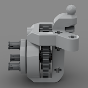
Congrats on the model! Can you please give more insight into what this exactly means, how it is achieved? I don't know how a proper boxer engine should work, but some people say this cannot be true with the lego cam/piston pieces. For example, there are 3 cams and 6 pistons, so they are paiwise connected/dependent. Is that true for the real engine? Furthermore, the cams can only be rotated 90 degrees, no 60 or 120 degree difference can be made (as would be realistic to achieve uniform spacing). That means that two cams will be 180 degree opposite each other, which means that 2 pistons out of the 6 are going to fire at the same time (on opposing sides). Is that realistic for this car? Or do we misunderstand something? -
Thanks, nothing specific, just the overall constructions is what I was curious about!
-
Looks cool on pictures, do you have a video of it floating? :) Though may be hard to capture.. Can you show details of the new parts you developed?
-
Grum's Shed
gyenesvi replied to grum64's topic in LEGO Technic, Mindstorms, Model Team and Scale Modeling
Merry Christmas! That sounds like a good adventure! :) -
Technic Pub
gyenesvi replied to jantjeuh's topic in LEGO Technic, Mindstorms, Model Team and Scale Modeling
Merry Christmas to You All! -
Zero's workshop
gyenesvi replied to Zerobricks's topic in LEGO Technic, Mindstorms, Model Team and Scale Modeling
I like the chassis construction a lot, everything is neatly packed in, and seems to drive well even with standard PF electronics! And looks cool too! -
Thanks, glad you agree! Not sure I understand why that is a concern? I agree it should be like that, and for that, soft long springs are needed, and this one is exactly that, the softest long spring. I expect it would actually behave that way under a medium sized model! Or do you mean that such force could pull the lower mount out? Yeah, kind of what I roughly thought too, although it's a good idea to cut the other end of the link and use the axle to fix into a drill or something, I did not think of that. The only problem is that it's hard to know when to stop, when it is the right size, when tenth of millimeters matter.. but maybe worth an experiment..
-
Thanks! What I tried to work out is something that could actually be moulded as a genuine lego part. Who knows, maybe they are reading these threads ;) I don't think the upper part would be any problematic, and even if the first prototype breaks with those 2mm bars on the lower end, I can use the drill to make the hole 3.2mm and make the bar connection stronger (would increase the bar surface area to 250% of the current one). Also, I think if those end parts were actually injection moulded, they'd be definitely strong enough, as similar parts do exist with bars, like this: In fact, some of these could be cut an used here for a DIY solution. The link end could also be possibly 'manufactured' from a 6L link, I just don't yet know a good way how to cut out a round bar from an axle.. any ideas (besides using a file)? Also, these bottom end parts would not be one-off parts for shock absorbers only, they could be useful for other purposes. The bars can be inserted into axle connectors too..
-
8L / 9L soft springs with 2 studs of travel in 1 stud diameter, parallel and perpendicular variants with pinhole / towball ends Hi folks! One kind of part in lego technic that I think could greatly be improved for certain situations is the shock absorber; I often find that existing ones are either small with quite limited travel, or too bulky in terms of length / width for medium sized builds. Another problem they have is the mounting points on their ends don't allow tilting in a compact space, like links / towballs could do. So in this thread, I set out to see how the situation could be improved in terms of part design, and what we can actually make ourselves using existing parts and a bit of 3d printing. For offroaders, I often find that short springs with 1 stud of travel are insufficient, while larger springs don't fit into medium sized (RC) models. There are tricks with which smaller springs can be used to achieve longer travel, but that often trades off space that would otherwise be used for other things. For example, springs can be moved inwards towards the centerline of the chassis, but that means that they occupy the space of the engine or trunk. Longer soft springs would be required to allow pushing them outwards next to the wheels, but the existing variants cannot really be used, as they are often too wide or too long, taking up significantly more space. So I asked myself the question whether it would be possible to make longer travel shock absorbers with minimal additional size? Ideally, only increasing the length, and keeping the width at 1 stud diameter? More specifically, what is the minimal length into which a spring with 2 studs of travel could be compressed? The design idea I realized that part of the complication comes from how shock absorbers must be assembled from (injection moldable) parts; the key problem is how to put the inner sliding part into the outer fixed part. It can be done in two ways: from the top or from the bottom. Older lego springs are assembled from 2 parts, the inner part clicking in from the bottom like this: This requires some tabs that click into place and that requires some molding tricks and also takes up some extra longitudinal space. However, RC springs are typically assembled from more parts, and the inner part slides in from the top (eliminating the need for a click-in mechanism), and then the two end mounts are screwed on. But screw-on parts are not easy to mold, and also cannot be made tiny but strong enough from plastic. Not too long ago, the thin long shock absorber for motorbikes came out, and I bought some as I was optimistic about them, only to realize they are way too long to be practical (11 studs), and their mounting points would also make them really complicated to use for things other than motorbikes. However, they also have some good properties: they are only 1 stud wide, have the (soft) spring inside, and also their assembly method resembles RC shock absorbers. So they looked like a good concept in theory. I started wondering whether it would be possible to make a more compact version using the same principles. My calculations for a minimal length were as follows. 2 studs are required for the sliding part when it's completely out, and two more studs are required as space to slide in. It needs at least 1 stud of overlap between the inner and outer part (the 6.5L and the 9L springs have about 1 stud of overlap only, so it should be enough). That's 5 studs so far, plus we need at least 2 more studs for the two end mounts, resulting in 7 studs in total. However, we need some more space for assembly/connection of the end mounts (for example by clicking in), and also for the spring itself as it needs to be a longer one, so probably 8 studs in total is the smallest length possible. As for assembly, the motorbike shock absorber sounds like a good overall design. It has two key features for assembly: the sliding part and the lower end mount are separate pieces clicked together later, and the outer shell has an opening on the top. These together allow for the sliding part and the inner spring to go in from the top (no need to click-in from the bottom), and it has a top cap that clicks into place later (however, this is possible because the top mounting point is more complicated, not just a simple pinhole). Also, the way the lower mount is clicked onto the sliding part takes up a full stud of space. Anyways, I figured that a minimalistic design could be something along these lines (the inner bar represents the spring here): The idea is that the top pinhole would slide in from the top to close the outer shell and hold the inner spring as well, and also that the lower mount could be pushed into the sliding part from the bottom. The top cap would need to be fixed into the outer shell to hold the spring securely, but the lower part could even allow for some flexibility: it could be replaceable and rotatable! Assuming a standard bar hole inside the sliding part (as the motorbike shock absorber part does have on the top end for the spring), the lower mount could be a part like one of these (or even this): The first would be a standard pinhole, while the second is a link end, allowing a towball connection, which would make the spring have multiple degrees of freedom (just like RC springs)! The following combinations could be made, even the existing towball on a bar part could be used as end: Furthermore, the lower end part could be rotated, so perpendicular springs could also be achieved, making it even more versatile: In order for this to work, the bottom connection should have a good amount of friction to prevent from sliding out by itself (under some moderate weight, like that of a wheel). It would be achievable by having the bar hole in the sliding part a bit tighter than normal. An advantage of these end mount parts would be that they would not be one-off parts for shock absorbers only, they could be useful for other purposes. The bars can be inserted into axle connectors too. As for the upper end mounting point, I did consider using a towball socket (link end) there as well. It is possible, however, it would be less practical. For one, that end is not easily removable / replaceable. Second, two link / towball ends would actually allow for too many degrees of freedom for the spring; it could rotate around its own axis, resulting in some unwanted wobbling (just like a standard link can). So I believe a fixed pinhole is most suitable on the top end. This could have a simple click-in assembly mechanism using some small tabs that would prevent it from coming out under weight. The practical implementation After thinking this through in theory for the ideal case, I actually realized that the motorbike springs provide a good starting point for the core parts, I can cut away the ends that I don't need and just 3d print new ends! So I did that, cut off 2 studs from each ends, leaving me with these parts (7L in total): As a result, the outer shell is 5 studs long, the inner one is 4.25 studs (overlapping with the outer one on 2.25 studs), and the spring is about 4.5 studs. Adding two ends results in a 9L spring. So I designed and 3d printed the following two mounts for the top/bottom; these simply slide into the end holes, but they are a tight fit, so they don't come out easily, but are still replaceable. The upper one also has tabs that prevent it from rotating. Unfortunately, the lower end of a sliding part does not have a standard bar hole, only a 2mm hole. For a 3d printed part it's not so much of a problem though, only it is somewhat weaker (still looks okay, maybe under load it could break). However, a drill can be used to enlarge the hole to 3mm or 3.2mm (the diameter of the bar hole). Luckily, 3.2mm drill heads also exist, although harder to get. So these parts resulted in a 9L shock absorber. To get an 8L overall length variant, I cut away further 1 stud length both from the outer shell and the sliding piece (on the top in both cases). Also, I had to use a 3.2mm drill to deepen the inner hole in the sliding piece from the top to allow the spring to slide deeper as the overall housing length decrease had to be compensated. Both variants work smoothly, and they are at least as stable as standard small lego springs. However, they are softer and can be used much more flexibly; they can be rotated and tilted in all directions. Next up is building something of medium size with these springs (probably in conjunction with one of my 3d printed brushless motors). One possible option to incorporate them in a more complex tilted way would be something like this (but obviously classical vertical positions are also possible): Let me know how you like this concept, whether you'd find these practical for building your own stuff! Cheers, Viktor
-
Indeed, deserves to be seen here! A 7 stud wide build with 3 RC functions is another testament on how much potential is left on the table by official Lego electronics!
-
Really amazing minification work! Looks easily recognizable and great that you managed to put 3 RC functions into that small volume, especially like the steering linkage!
-
[HELP] Generic Building Help Topic
gyenesvi replied to Jim's topic in LEGO Technic, Mindstorms, Model Team and Scale Modeling
Anyone else having invisible white text on white background on the Technic subforum? Happens only here, other themes render well. Checked on multiple devices and multiple browsers, same everywhere for me. @Jim what's happening? -
Generic Contest Discussion
gyenesvi replied to Jim's topic in LEGO Technic, Mindstorms, Model Team and Scale Modeling
If there's only weight limit, then what's the contest really about? I think the B model requirement makes it more interesting, that's where we started from, no? I don't think there's a need for requiring a part list. For such small builds, it should mostly be possible to see on the photos that parts of the B model are also in the A model. If something is not visible, it's possible to ask where it is, or even request more photos that make certain parts visible. -
Generic Contest Discussion
gyenesvi replied to Jim's topic in LEGO Technic, Mindstorms, Model Team and Scale Modeling
Yeah, I think we converged to that as well, and about 300g seems to be a good limit. One questions we had is whether tires should be counted into the weight in order not to penalize cars too much against builds that don't have wheels. -
Well yeah, it can be considered a little bit illegal (nowadays), but how would it look? :) Also, with the 1x2 variant, would it actually move? It may be a friction connection, depending the exact pinhole size on the fender (might not even hold it, might hold it strongly). I think on the liftarm end, it would be a strong connection definitely.
-
That's a really nice reverse engineering effort, great work! So just to clarify what that exactly means, how do you set which control lever controls which motor and whit what speed / direction? And which unit runs that logic (the program that you code on the web)? Does it get sent to one of the units? Or does it run in the browser on a laptop for example?
-
I like how the engine is implemented, nice trick! Just curious, how do you imagine using the same piece to create different angles / offsets for two rows of pistons? @kbalage how would this part work for mounting the front of the front fender? Would it have enough space to fit? The headlights might slightly be in the way.. You could try it mounted on half pins with studs out, or maybe even better, without pins with the studs inwards. Not sure it would look better, and would hold the fender properly, but maybe worth a try. Or maybe even better for color matching, this piece could hold the fender with just one stud connection in both parts, and a round black tile could be placed under it to match the bottom grille section.
-
The Bug 6x6, Rough Sand Trials
gyenesvi replied to Kamil's topic in LEGO Technic, Mindstorms, Model Team and Scale Modeling
I think that should be fine, the old grey and the newer red ones are identical I think. Does the clutch piece engage it properly? Did you check the orientation of the orange wave selector, with respect to the limiter connector piece, and wrt the sliding shifting piece? When the connector in the front is pointing upwards, it should be in neutral gear. Now that's weird, that is a very standard gear mesh, it should work. In fact, replacing the 12T with a (thin?) 14T should not work. Something seems off there. -
It's not exactly a 9L thin liftarm, it's more like a link, it only has 3 pinholes, two on the ends, and one in the middle. And as far as I remember, the material is softer, the piece can bend quite easily.