
Heppu
-
Posts
40 -
Joined
-
Last visited
Content Type
Profiles
Forums
Gallery
Everything posted by Heppu
-

[TC28] Metal lathe (large scale)
Heppu replied to howitzer's topic in LEGO Technic, Mindstorms, Model Team and Scale Modeling
That is some serious amount of gearingin crammed into one block of intricate mechanisms Since you mentioned it being an interesting challenge, I would like to see and better understand how the mechanism to attatch and fasten a work piece to the chuck works. -
I also did not realise the first image was a video. The functionality looks pretty nice already! The inverse kinemattics I dont feel are complicated at least for the 3 degrees of freedom robot being built here. Maybe for the 6-DOF ones like in the video linked by oracid it starts to get complex. For 3-DOF you just need to adjust the relative speeds at which each of the 3 motors turn to have each motor reach the desired angle at the same time.Trajectory generator is required for longer movements to generate "middle points" or otherwise some inverse kinematics solutions that have the end effector travel trough the x-y origin between 2 far away points can lead to the end effector not maintaining linear movement between the points. Here are some pics and videos of my attempts at 3-DOF Delta robots if interested for inspiration https://www.flickr.com/photos/heppu/albums/72157704649606362/.
-
Always cool to see delta robots and robotics projects in general! I have such a fondness to having built a few of delta-robots with Mindstorms myself. Excited to see your progress and final application with this. I'm unfamiliar with the motors you are using, but if you are unable to figure out the starting angle of your motors, you could always implement some startup sequence which raises all the motors slowly up against some stopper and try detect when they stall to reset the encoder to a known angle. For smoothing out movements, consider also how much slack is introduced by the gears. If you suddenly switch the direction you move the motor in, the slack in gears can cause some jerkiness in the movement if not accounted for. This effect can be really noticeable especially in delta-robots where the end effector can be far away from the supporting structure.
-
[MOC] Alfa Romeo P3
Heppu replied to Davidz90's topic in LEGO Technic, Mindstorms, Model Team and Scale Modeling
Nice vehicle! Is there a way to brace the front lights better to keep them aligned? -
Hi again EB. It's been a while, but I have expanded the collection with a 3rd vehicle in the same scale: a Development Drill. DD422i Development drill with dual booms for efficient tunnel face drilling. Designing this proved surprising difficult given the 1:14ish scale. The body came out to be even 8 studs wide which does not always mesh nicely with Technic :). At this scale many of the functions are not that 'impressive' to play with but this was designed primarily for display Manual functions: Articulated steering (from the knob at the back) Adjustable drill booms Openable cabin doors Hydraulic jacks to lift and level the machine during drilling Cable reels (electricity and water) The whole trio was on display recently at a local Lego convention. For that occasion I went and built a backdrop cutout of an underground tunnel so that the exhibition visitors would better understand what these machines are used for. Since my initial post, I have also done major redesign to the front-end of the loader. Now the bucket has enough reach to be lifted high enough to dump ore to the bed of the truck. Thank you for reading :)
-
I have only used python to drive my EV3, so cant really help with the native block programming language. If you feel something is wrong with the IR, maybe build a simple program that just measures and outputs the signal strenght to read? Then observed if there are major fluctuations in the readings while the sensor and source of IR are stationary. This would narrow down troubleshooting the actual issue or identify potential other sources of IR nearby. For the motors, apologies if I was unclear. I meant to switch the ports the motors are connected to. So B to C and C to B in your case.
-
If it shoots and identifies IR signal correctly while lifted off the ground, my guess is either your program or physical wiring incorrectly drives the motors in reverse direction to expected. I would try swapping the cables of the 2 driving motors with each others ports on the EV3
-
Benny's Space Mech
Heppu replied to CheungsLegoCreation's topic in LEGO Technic, Mindstorms, Model Team and Scale Modeling
Cool mech! What do you use to control it and how complicated is that setup? -
[TC26] Large scale snowmobile
Heppu replied to howitzer's topic in LEGO Technic, Mindstorms, Model Team and Scale Modeling
Excited to see how the track will fit and look at this scale. Those new shock absorbers look so much more realistic in larger scale models. -
Nice looking baja truck! looks like it will be fun to drive and play around with. Outside of colour scheme, have you considered what makes this specifically an Arctic vehicle? What I can think of could be: Less need for air intakes for cooling, reinforced front and underside to cope better when hitting a snow bank, maybe a snow plough to clear our a path in rougher terrain? Looking forward to seeing this in action!
-
Thanks for all the nice comments <3! At one point I experimented with safety rails on the loader in the digital model, but I couldn't design connection points for a folding mechanism for them that was not too flimsy so I decided not to add them. Yes there is a little flex in the trucks articulation. It's not fragile but it does tend to bend, especially if the bed is raised. That area could be improved for sure.
-
Pair of machines used to transport rock ore in underground mines. Built in roughly 1:14 scale.The machines are always designed as a pair; they fit in the same tunnel size and the trucks load capacity is 3 of loaders bucket scoops. I tried to build them as close to the real counterparts while also retaining some functionality to make the fun to play with. Both vehicles are in their "stock" configuration with only proximity detection system installed (6 white round sensors). LH517i Loader Loader designed for 5m wide tunnels. 17 ton load capacity bucket. Manual functions: Articulated steering (from a knob at the back) Bucket arm lift (from a knob at the back) bucket tipping openable door The bucket is painted red as Lego does not have a suitable red bucket at this scale. The current one is also comparably too short but the width is correct. Also I might want to revisit the loaders arm geometry as currently it can't lift it high enough to load the truck from flat ground. The rear white sensors are attatched using blue tack. TH551i Truck Truck designed for 5m wide tunnels. 51 ton load capacity. Manual functions: Articulated steering (from a knob in the front) dump box tipping openable door More pictures can be found from my Flickr Gallery: FLICKR Picture of 6m wide tunnel model variants for reference: Thanks for reading :)
-
EV3 AC Power Adapter
Heppu replied to pdmarsh's topic in LEGO Technic, Mindstorms, Model Team and Scale Modeling
Thanks all, hope this proves to be useful to others as well! I actually started out with designing a clip version, but creating small elastic clips that don't break is really hard with a 3D printed part. Also in my version due to the compressed tension in the battery holder clips, the screws are mandatory to hold the lid in place. The electronics would need to be separate from the cover for a clip version to be possible. -
EV3 AC Power Adapter
Heppu replied to pdmarsh's topic in LEGO Technic, Mindstorms, Model Team and Scale Modeling
I 3D printed a new battery box cover for my EV3 for a custom AC adapter earlier this year. Material list is: 3D printed battery box cover (Stl file uploaded here: https://bricksafe.com/pages/Heppu/wip-/ac-adapter) 2x 15mm M2.5 screws DC barrel jack socket AC/DC wall power adapter 12V/3A (9V/2A is enough for most use cases) Electrical wires (red=plus, black=minus in above picture) Battery holder clip from a AA battery box & a metallic washer as contact points to EV3 (Hot glue for attatching the battery clip & tin to solder the electrical wires) Hope this helps anyone attempting to do similar projects :) I'm always open to answer questions if needed. Philo has instructions for a similar project for Mindstorms NXT: https://www.philohome.com/nxtsupply/nxtsupply.htm Hes' is maybe better than mine having a fuse, but I've had no problesm with mine so far. -
Really cool project and addition to an already amazing display of automation possible with Lego! Shame about the motor, hopefully it's salvageable somehow.
-
42123 McLaren Senna GTR
Heppu replied to Ngoc Nguyen's topic in LEGO Technic, Mindstorms, Model Team and Scale Modeling
Check Bricklink inventory for extra parts: https://www.bricklink.com/catalogItemInv.asp?S=42123-1 -
LM Vision Command for WinXP
Heppu replied to jarstx's topic in LEGO Technic, Mindstorms, Model Team and Scale Modeling
Ahh, thank you so much for the insightful info! Yeah wasn't expecting anything spectacular from the camera. Was just curious because of the rather uncommon 356x292 resolution that there might be some better setting available. I will just stick to the Linux drivers then and try to deal with the bad quality :) -
Huge congrats to everyone who participated and especially the winners. Inventing new mechanics to move balls is a hard task, kudos to those who could.
-
LM Vision Command for WinXP
Heppu replied to jarstx's topic in LEGO Technic, Mindstorms, Model Team and Scale Modeling
Oh wow, a pleasant surprise for someone to revive this topic just now! I've been toying with using just the camera for a project and got it working almost out of the box in Linux Ubuntu 19.04. with v4l2 drivers. The problem I'm facing is that with those drivers, the maximum resolution is 356x292px. Also the picture quality is also really dark and grainy. For comparison, here are some example pictures taken of the same model with different cameras in same lighting conditions. * all photos scaled to 640x480 resolution. So Im wondering, what are the improvements you experienced using the winXP drivers? Would it be beneficial for me to try and get this running instead with a WinXP VM? I would be ok if the image quality could be comparable to the Playstation 3 eye camera with 640x480 resolution. I've understood that 640x480 should be the theoretical max of the Logitech quickcam inside the Lego camera but the Vision Command software never enabled that. -
[TC23] Stewart platform GBC
Heppu replied to Heppu's topic in LEGO Technic, Mindstorms, Model Team and Scale Modeling
Sadly it's not really about the reliability but the speed. The current version processes balls at rate of ~1 ball/3sec. I would need to make it 3 times faster to be eligible for GBC standard of 1ball/sec.Big modifications would be needed to achieve that which I personally think I don't have time for atm. Something like that would indeed be cool. In general I'm not sure how viable using Mindstorms in multi-person organised GBC is. If something goes wrong, it can be almost impossible to quickly fix someone elses Mindstorms project. -
[TC23] Stewart platform GBC
Heppu replied to Heppu's topic in LEGO Technic, Mindstorms, Model Team and Scale Modeling
An update maybe? Or more likely a postmortem on all my attempts to make the stewart platform work as a GBC module. Unless some breaktrough happens, I'm not going to get this thing servicable for the contest. Here is the latest version: It is too slow, unreliable and not even close to what I had in mind when starting the project. It does not capture what movements the stewart platform is truly capable. Also I use 2 extra motors at the input feeder to just make the testing easier. In the future I had plans to operate the gate that feeds 2 balls at a time to the platform by just opening it mechanically using the platform tilting down to trigger the gate. I truly tried but no prototype really came close to what I wanted. The original pendulum idea was the one I fiddled with the furthest. The concept was 'fine' but the single axle connection meant that there was too much friction. Pendulum swings were too unpredictable and varied based on the weight of how many balls was in the scoop, often overshooting the desired ouput area with heavy loads. I got frustrated and tried to simplify the system by making the ball track static to the platform. First I tried a weird spiral but abandoned it because it would require another module to first lift the balls to required height. (Also it blocked the view of the main mechanisms which I did not like. Then I started experimenting closer to the latest version shown in the video above with a long circular track. It would have been nice to lookat, but the long track would have been too slow to meet the required 1ball/s requirement. That is why I decided to experiment with the more straight track shown in video instead (which is still too slow anyways). Anyways, good luck to anyone who is still participating! I'm kind of out of motivation to fix this machine when I know I'm most likely not going to present it at any exhibition as part of a GBC loop. I will still continue develop the stewart platform itself, but to some other purpose entirely. Cheers! -
Cool system and thanks for the video! Explains the mechanism better for sure. Impressive it can take so many balls at once! And you seem to be the first one to showcase a functioning module. I'm having so little time to work on my entry to iron out it's kinks, but hope to get something that works before the end. Also, glad that the angled gears approach worked. Personally I like to look of the model more like this. From the video it seems to work without issues using all the gears too and you gave good reasons to use them instead so use whatever is best for you.
-
Looking forward to seeing a video of this. Sometimes just looking at pictures it's hard to grasp the full mechanism . Did you ever consider replacing the chain of gears at the top to bewel gear connections to reduce the amount of gears needed?
-
[TC23] Stewart platform GBC
Heppu replied to Heppu's topic in LEGO Technic, Mindstorms, Model Team and Scale Modeling
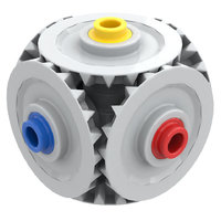
Great to hear that everythig seems to be good to go ahead! I finished most critical parts of the control system code. Most important I calculated the inverse kinematics for the platform. It works such that I can input the height of the platform, tilt angle and the direction of the tilt. These are then converted and sent to desired motor angle coordinates. Second I made a reset function that calibrates the motor angles to a known value. It drives all the arms 1by1 towards the base until they drive against the axle with red bushes and and become 'overloaded'. Physically not much has change yet. The platform legs are changed from the modified bent liftarms to straight 7L liftarms to get a geometry that enables larger range of motion. made a small video to showcase the progress: In it the motors are calibrated and then the platform does 3 loops around at 10° angle. I was hoping I could pick up balls by tilting the pendulum up from below the box. Seeing the range of tilt angle and height now, I fear the angle range available might be too small for that. Also getting the pendulum to stop at exactly the desired position might prove difficult. These all might mean that the input box might also need a motor that is synced to load the pendulum when it is in position. We shall see. -
[TC23] Stewart platform GBC
Heppu replied to Heppu's topic in LEGO Technic, Mindstorms, Model Team and Scale Modeling
Sadly I do not own any working EV3 or other mindstorms hubs. I will use ev3dev operating system on it that supports both EV3 brick and Brickpi. There should be no major perceived advantage to using a raspberry.