
Hod Carrier
-
Posts
1,007 -
Joined
-
Last visited
Content Type
Profiles
Forums
Gallery
Everything posted by Hod Carrier
-
That looks good. I think that it should work fine like that, subject to real-world build and testing. I know you said you were thinking of removing the top link, but I see you have found another way instead of attaching the top of the mechanism in a way that suits your design better. Well done. I did a quick and dirty mock-up in Stud.io to see what the problem might be. I don't know if I got all your parts choices, measurements and spacings correct so I might be way off, but I managed to get to the magic 16 degrees without affecting the look of the model. The problem is not the slopes themselves but the supporting parts that the slopes are attached to; specifically the dark bley inverted slopes underneath. You just need to create some space for the corner of the bogie to move into, as the bogie part will move sufficiently far over the top of the inverted slopes to give you those extra few degrees of movement. I have found them to be OK and not too weak, and I think others would agree. Your solution does look much stronger for sure and would take away any worries about performance of the part, especially on a heavy train. Ultimately it's up to you to choose the design that works best for you.
-
You're very welcome. This is the beauty of the community. Everyone is willing to pitch-in and help share their ideas, experience and expertise. Never be afraid to ask whenever you feel you need some help or feedback. It looks promising. It's a little hard to see what you've done inside from that angle, though. That depends on a number of things, including the wheelbase of the vehicle (the distance between the axles). The longer the wheelbase or the tighter the curve, the more movement you will need. I don't have a mathematic formula that allows you to calculate how much movement is needed and arrived at the required amount through trial and error, which is the reason why sometimes you have to test build things and try them out. Happily the wheelbase of your end car looks similar to that of my freight wagon. For that model, I found that I needed around 16 degrees of movement for a wagon with a 25 stud wheelbase to match an R40 curve. You could get away with less if you're prepared for the axle not to turn all the way into the curve, but the trade-off with that approach is that the wheels will "scrub" across the inside of the rails and cause friction. It looks very chunky. I'd keep things simple and just use a 2x2 turntable plate attached to the four holes on the bottom of a 3x3 plate built into the floor of the end car. It's surprisingly strong and gives you the half-stud offset you need for a 7-wide design. You're welcome. There may not be a huge amount in the discussion that applies to Talgo designs, but you may still find it interesting. Sounds like a great plan. We can have a pan-European Talgo-Fest. I might have to have a go at building one myself.
-
@Imanol I've been reading the thread and looking at the various renders to try and understand what the issues are in order to make some sort of assessment. I have no direct experience of replicating the Talgo wheel arrangements, but I have spent a fair amount of time looking at other articulation and axle arrangements. The rodal design shown by @Ferro-Friki looks sound and should give you the axle steering that your train will need. However, as he says, you will need to make sure that you allow enough space between the cars for them to articulate without the car bodies striking the axles (which I suspect is what is stopping his Alvo from using R40 radius curves). The rodal design also provides for car-to-car coupling, so there isn't any need to go looking for another solution. If you look at his cut-away render of his Alvo, you can see that one side of the articulation is built into the car on the left side while the car on the right side sits on the red axles and is joined by lowering the car onto these points. This connection will be more than strong enough to support the weight and keep the train together provided that the attachment points inside the car are built into the structure. I would personally use something like a Technic Axle and Pin Connector Hub with 2 Axles (PN:27940) with a Technic Brick 1 x 2 with Axle Hole (PN:32064) on each side built strongly into the structure of the car, but you may need some other solution that fits better into your design. In your own render, you have made an error by making the design of the articulation the same on both sides and have also made both sides 1 stud longer than necessary. As for the weight of the cars, I still don't think you should worry so much about it. Excessive weight really only has two downsides; it requires more power to move it and it can make any problems you have with friction worse. Weight doesn't really have a negative impact on the coupling, especially for a vertical coupling system like this one. Carrying the weight simply means ensuring that it is transmitted down through whatever structures you have into the wheels that are required to carry it. In this case the design works fine because there is a weight-bearing attachment on the top of the axles to help carry the weight. In addition, each side of the rodal is going to be balanced when the cars are coupled because all the cars are likely to be very similar in weight. Your implementation of the rodal design currently intrudes 5 studs into your cars, but this is with a 1 stud gap between the cars. As mentioned already, you can lose 1 stud off each end straight away just by copying the design more closely, which will bring the intrusion down to 4 studs. If you extend the gap between the cars to 3 studs as recommended the intrusion is brought down further to just 3 studs, which could possibly be reduced even more by changing some of the parts and the way that it is secured inside the cars. Looking at your earlier cut-away renders of your cars, I think you could possibly live with a 3 stud intrusion without having to sacrifice too much of the interior, which you can achieve by following the proposed rodal design more closely. If you can successfully work these ideas into your design you may not need to discard the top link at all and retain the extra dynamic stability that this will give your train. I like your idea for the end car coupling and am glad that you have avoided the mistake of using a pivoting magnet on this side of the coupling. Having pivoting magnets on both the locomotive and the end car would be fine under tension (pulling) but not under compression (pushing), as the coupling bar to the axle under the end car almost certainly would be deflected to one side, pushing the axle out of alignment. My only concern with your proposal is that it doesn't appear to have enough articulation for small radius curves like the standard R40. You may have to consider cutting back the sides to give the axle more space to turn. I think you're getting close to a buildable design now and, by implementing @Ferro-Friki's ideas, you should have a train that looks cool and runs well. Talgos are extremely tricky trains to engineer, but it looks like you're on your way to a winner. If any other thoughts come to me I will add them to this thread. Any questions, just yell. I don't recommend this. I tried using free swiveling axles on a long-wheelbase freight car and they don't work. There needs to be some mechanism to allow the axle to steer and turn when it needs to (and to make sure that it turns the right way) and to bring it back to the central position when it goes onto straight track. Free swiveling axles just flop about in any direction they feel like going and then get stuck in the wrong orientation. If you feel like wasting a couple of hours you can read more about some of my adventures in axle articulation here.
-
I don’t think that supporting the weight will be an issue with the current design, as long as the ball and socket parts are built strongly into the structure of the car bodies. But yes, I think your biggest problem with the current design will be derailing and friction on curves. I understand that you don’t have track or bricks to try things out, but sometimes it’s cheaper to do this first and build any changes into your design before building it than having to alter everything afterwards. It’s a big train which is going to be expensive to build anyway, so trying out some of the design features first might save you money overall.
-
[Virtual MOC] 2020 Oslo Trikken (Tram)
Hod Carrier replied to Hod Carrier's topic in LEGO Train Tech
Yeah, I agree. Thank you, sir. That's very kind. -
I fear you're going to have some derailing and/or friction issues if you use fixed axles as shown in your design, as the length of the cars is quite big. You may also need to consider using some kind of articulation between the cars to steer the wheels around curves. There are some ideas from other builders on Flickr if you search for "Lego Talgo". Have a go at building some basic chassis to test and see what happens. You may find that the articulation provides a way of coupling the cars more securely than by using towballs, which would solve two problems in one. As for strength and structural integrity, I wouldn't trust the stability function in Stud.io as it doesn't always correctly identify areas of weakness. Try and use lots of overlapping parts to give strength and check your build as you go.
-
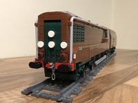
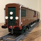
It's a fair representation of a Hall, perhaps with better proportions than the Emerald Night. It is maybe the best we can expect as an official offering at this size, but I'm not blown away by it. The loco may be nice, but the coaches are horrible and the station is a take-it-or-leave-it for me. I expect it to be a roaring success. I appreciate that this is damning with faint praise, but that's my feeling.
-
[Virtual MOC] 2020 Oslo Trikken (Tram)
Hod Carrier replied to Hod Carrier's topic in LEGO Train Tech
Thanks for the feedback folks. I'm also liking how it looks, especially when all lit up. It's certainly a distinctive vehicle and would have made for a brilliant addition to the streets of Oslo. Do you mean the sleek modern styling and the way that it combines the aesthetic with the practical, or that it divides opinion along intensely fought lines and is incompatible with systems that went before it? -
This is another dip into the vaults for a design that been sitting on the books for quite a long time. It was almost exactly 5 years ago that I had the idea to design and build a tram. It was something that I hadn't tried before and I wasn't sure how I would do. Part of the problem for me is that they don't look particularly distinctive, unlike trains that come in a bewildering variety of sizes, shapes and colours. I spent a good amount of time trawling through the internet looking for inspiration, which is when I came upon the 2020 Oslo Tram concept. The story of this design concept goes back to 2015 when Sporveien, the public transport operator, started the tendering process for a new tram to replace it's ageing fleet. Two young Norwegian designers, Taral Jansen and Mikkel Brandt Bugge of design studio Norwegian Attitude, submitted a design for a brand new high-capacity tram customised to suit the needs of Oslo while reflecting Scandinavian design principles. More information about the project can be found on the project's Facebook page. My first attempt at reproducing the design was not especially good. One of the main problems was that there was a mismatch between the width of the cabs and the width of the car bodies, which just didn't look right to me. I tried making the cab front wider but it just made the problem worse. The other issue was that, when I rendered the design, a lot of the features simply disappeared. This is something I have experienced a few times before when trying to render black and trans-black parts. I was very underwhelmed by the whole thing and so I just put it away and pretty much forgot all about it. That was until just a few weeks ago when I visited Oslo for a few days. I already knew that the 2020 concept would not have been realised as it would have required bespoke vehicles that would have been incredibly expensive. However, I was excited to see what types of vehicles would be running on Oslo's tram network given the amount of time that had passed, and whether anything of the concept design had been incorporated. So imagine my disappointment when I came out of the Oslo Sentralstasjon to see that the backbone of the Oslo tram service is still being operated by Duewag SL79s, some of which are already over 40 years old. Don't get me wrong, I enjoyed riding these older trams, but I had expected something a bit more modern. With my interest rekindled I came home and decided to revisit my model and see what improvements I could make. The first item on the work-list was to reduce the width of the cars so that they matched the cabs. Using a combination of brackets inside the roof and floor of the model, I was able to reduce the width by 1 plate on each side. Now the width is consistent all the way down the tram cars, going from 8 studs wide to half a plate over 7 studs. I also substituted some parts that were not available for others that are in order that the design can be buildable and replaced the windscreen with a much deeper alternative. I have also learned a thing or two about the rendering process in Stud.io in order to try and get the design features to be more visible. All that said, the most striking aspect of the design is still not visible when rendered. The "illuminating lines" around the cab windscreens and along the sides of the cars were just not showing up. So, by swapping out the trans-clear for luminous parts and adjusting the background colour and light settings in the render menu, I was able to replicate the effect of the lights. Applying the same trick to the inside of the cars meant that I could also simulate the effect of internal lighting. I'm unsure if I shall ever build this model, but I am at least happy now to present it for feedback.
-
Thank you for the very generous name-check. I like how you’ve developed the coupling concept and made it work for you. But I especially like the beautiful railcar you have built. It’s a real visual delight and a joy to watch in motion. Congratulations on yet another spectacular build.
-
I suspect that at least some of this is as a consequence of the requirements set down in the Bricklink Designer Program Guidelines, which stipulates that certain criteria must be met (click for details). Having browsed the Series 1 entries, I thought I'd have a look at the submission requirements to see if it's something I'd like to have a go at for Series 2. As such, I've been reading through and trying to absorb the guidelines and I'm not sure that I'm sufficiently tempted. While I can understand that some of the requirements exist for a reason, I can also see that it can result in a somewhat dissatisfying experience, as has been reported here. It seems that the requirement for clear instructions has resulted in a situation where rigid adherence to the guidelines produces unnecessarily bloated instructions where a slightly more flexible approach could have dealt with this problem. That said, I think the designer may have slightly misunderstood part of them. The requirement for the first step is to have no more than 5 elements, but from there on out it can be up to 5 different elements and a maximum of 10 elements per step. If there are 17 glass panes to fit, this is going to take at least two steps depending on whether or not other elements are required to be used and if building them up extends the construction by more than 12 studs in any direction. Exceeding any of these limits would necessitate an additional step. I also wonder whether or not the designer tested the instructions using a third party (and probably less experienced) builder to ensure that they were adequate and to gauge the quality of the building experience. It's a shame to hear the negative comments about this design, as it promised so much. Looking at it, I had pigeon-holed it with as a Modular building rather than as a Train-theme design. I'm sure that some of the negative aspects could be addressed by modding the kit, though.
-
[Virtual MOC] Stadler Flirt UK - TfW Class 231
Hod Carrier replied to Hod Carrier's topic in LEGO Train Tech
@LEGO Train 12 Volts Thank you. You know me. I just keep going until I get it as close to reality as I can. @Ashi Valkoinen Thanks for the welcome. I was a little worried that you'd also been working on the UK version of the FLIRT and I didn't want to tread on your toes. -
[Virtual MOC] Stadler Flirt UK - TfW Class 231
Hod Carrier replied to Hod Carrier's topic in LEGO Train Tech
@Darkkostas25 Thank you. That’s very kind of you to say. -
[Virtual MOC] Stadler Flirt UK - TfW Class 231
Hod Carrier replied to Hod Carrier's topic in LEGO Train Tech
Thank you, gentlemen. @Asper @Feuer Zug It’s a model using parts ancient and modern. These were the best techniques I could find to recreate the various vents on the roof. @Ts__ I agree that the side window is the wrong size and shape, but that was the compromise that I had to make to ensure that the slope and taper of the cab could be made. There’s quite a lot of snotting and supporting structures going on inside that had to be accommodated. I spent a lot of time wondering if I could have done that detail better, but concluded that the only way I make it better was to make the rest of it worse, so I decided that I could live with it There have been a lot of compromises made, such as the inset headlights. The original design was closer to the real train, but it would not have been possible to include LEDs. What you see here is probably the most buildable version in the closest design I could make. No news on the prize as yet. -
Sorry for not posting anything up for a while. I needed a bit of a break after the hullabaloo of OcTRAINber. I thought I'd share what I'd been working on prior to OcTRAINber taking all my time. I had intended to build this but I'm unsure if that will now happen, so I'm sharing this as a virtual MOC. The Stadler Flirt has been a feature of European railways for several years, but it's only recently that Stadler has been providing these trains to the UK. Obviously this meant that the design needed adapting to suit the UK rail network's requirements, but I think that the resulting train is a very handsome thing which is proving popular among those who use them. The first versions to arrive in the UK were for Greater Anglia and came in two forms; a semi-articulated 12-car electric train (Class 745) for services between London and Norwich and Stansted Express, and a 3 or 4-car fully articulated bi-mode train (Class 755) for regional and local services. I had wanted to build a version of this train, but the livery used by Greater Anglia is quite complex and would be difficult to reproduce in LEGO. 745009 Stowmarket 13/05/22 - 1P51 1600 Norwich to London Liverpool Street by Ryan Hayward, on Flickr 755412 Turves 20/04/22 - 2E76 1156 Ipswich to Peterborough by Ryan Hayward, on Flickr Luckily for me, a second batch of Flirt UK trains were under construction for Welsh operator Transport for Wales, and the livery that was being applied to their trains was a lot more LEGO-friendly. As with the first batch, these units for Wales would come in two different forms; a 4-car single-mode diesel-electric train (Class 231) and a 3 or 4-car tri-mode train (Class 756). At the point where I started work on the design, the single-mode Class 231 was the only version in existence, with deliveries and test-running only just having begun. As a result, this was the version that I based my model on. 231002. by curly42, on Flickr And this is my version, rendered in UK-scale friendly 7-wide. There were a few challenges to overcome with this design. The train has a very distinctive body profile as well as that cab shape. It took several attempts at both to get to a final design that would be both buildable and look right as well as be able to take lights in the cab front. Power and control would have been distributed throughout the train. In common with the LMS Articulated Railcar, the Flirt would have train motors mounted on their sides together with weight bricks within the body in the windowless sections just behind each cab driving Technic bogies, as conventional use of these motors would be too big. There would have been a battery box hidden in the train toilet with a PFx Brick in the central "power pod". I had been busy researching magnetic connectors for the wiring runs between cars when I broke-off from working on the design of this model. The sloping cab tapers towards the front of the train, which I've had a go at capturing. Roof-mounted equipment has also been modelled as accurately as possible. The "power pod" containing 4 diesel motor-generator units. The detailing on the sides has necessitated a fair amount of "snotting", but it looks OK. Hopefully it would be strong enough when built. As always, thoughts, comments and feedback are welcomed. I doubt that this train will ever get built, as I'm currently busy with a non-railway project, but who knows how I'll feel about it later.
-
This is not my own creation, but I saw this on Flickr and thought it was hilarious and I thought I'd share it with you. Enjoy!! Lego Rc Drift Train by Nathan Hake, on Flickr
-
As we say in the UK, I think you was robbed. Your standard of finish and presentation was waaaay better than mine and I had you down as the overall winner this year. No doubt your wonderful creations will be getting lots of admiring attention this weekend at Bricking Bavaria, which will be richly deserved. Congratulations nonetheless for your win.
-
[ocTRAINber MOC] St. Boniface Golf Club Foot Bridge
Hod Carrier replied to Supplement_Creatif's topic in LEGO Train Tech
Winner at the first attempt!! How about that!! -
[OcTRAINber MOC] LMS Articulated Railcar (1938)
Hod Carrier replied to Hod Carrier's topic in LEGO Train Tech
Thank you everyone for the support and amazing feedback throughout the design and build process. I haven't always enjoyed every stage of this build, but I have learned a lot that I can take forward into future projects. It's never certain how the judging will go, and there was a lot of really good competition. Now I'm going to have to think of a layout to make best use of these switches. -
OcTRAINber 2022: The "Rebuilds & Retrofits" Challenge!
Hod Carrier replied to Daedalus304's topic in LEGO Train Tech
@Daedalus304 Very many thanks to you and the guys over at BMR for organising another enjoyable OcTRAINber contest. It's your hard work in pulling it all together that makes it work. Well done to everyone who entered and to the winners. I think the new format is better than the old one (should it be SepTRAINber as well as OcTRAINber...?) and clearly makes things a lot easier for you guys too. -
Scale is always a very personal thing, unless of course you're part of a group, in which case a scale would need to be agreed upon. It something that not even TLG themselves seem to agree upon, as there's a huge difference between the size of various official offerings that might be expected to go together. So in this regard, there is no "wrong scale" for anything. Indeed, we have regular contributors here that build in scales outside of what is considered to be "normal". However, all that said, where scale has not formally been agreed, there is an almost internationally understood formula regarding overall size which allows for flexibility of operation and for cooperation between designers and builders. Anything that falls outside of this removes that capacity. My own personal view is that the LEGO Minifigure has such unnatural proportions that I wouldn't base any decisions about scale around it. For trains, it would be far more logical to scale according to the track gauge we've been given to use. Employing the back of a fag packet, I worked out that LEGO track gauge is around 1:38 scale. In this case, your designs are probably much closer to scale than most others. The obvious problems that go with a much larger scale are size and cost. If my eyes are not deceiving me, your Allegheny design is 12-wide, which makes it 50% bigger than a regular 8-wide design and, therefore, at least 50% more expensive. As your render of the loco on R104s shows, it also needs much more space in order to be run. If your proposal is to offer these designs as kits, this may become a limiting factor on their desirability. It's already been proven that larger scale models allow for greater detailing and accuracy, and it may be that the demand for these models will be more for static display rather than for running purposes. Ultimately it's going to be for the market to decide. It would be interesting to know how you would price the Allegheny once you've included packaging, instructions, marketing, shipping, etc, etc. The great thing about scale is that it is universal. If you decide upon a certain scale then you will find that US, European and British models will all appear correctly proportioned when compared to each other. The problem is that the LEGO trains community as a whole has not done this, but rather has decided upon a formula instead which takes no account of scale.
-
Do you tend to stick to your nationality?
Hod Carrier replied to LordsofMedieval's topic in LEGO Train Tech
It’s a thought that has never occurred to me at all, and I really don’t think many people would be worrying about it. In fact, I’m not sure about the nationality of most builders (I’d never have known you were American if you hadn’t said it) and it doesn’t bother me in the slightest. I’m sure we all build whatever appeals to us wherever it comes from. My own record is mostly British, but that’s really just because I know more about British prototypes than, say, American, for example. I do find, though, that I do get inspired when I travel abroad. My most recent trip was to New York, so maybe I’ll build something from that region next. -
Ah, that’s really galling. But sometimes you just don’t know how things will go when you place these orders. But it doesn’t take anything away from the stellar work you’ve put into all of these builds and designs. You’ve really achieved some fantastic results and have worked very hard to make not just two but three versions.
-
It’s so hard to make tiny builds like this one work exactly as you want and still look right. I’m so glad that you’ve been able to make some changes that improves on both aspects of the design. I’m really glad that you didn’t give up on this and kept on working to make it better.
-
[OcTRAINber MOC] LMS Articulated Railcar (1938)
Hod Carrier replied to Hod Carrier's topic in LEGO Train Tech
Thank you. But please, no bowing is necessary. I’m not a master. The techniques I’ve used are in the reach of everyone.